Transkripti
1 Hap shoqëri aksionare"Shoqëria e menaxhimit të Holding" MINSK MOTORNY ZAVOD "Motrat me naftë D-245.7E4, D-245.9E4, D E4 OPERATION MANUAL 245E RE Minsk 2012
3 Përmbajtja 3 245E OM 1 PËRSHKRIMI DHE FUNKSIONIMI PËRSHKRIMI DHE FUNKSIONIMI I NAFITËS Qëllimi i naftës Specifikimet Përbërja e motorit me naftë Projektimi dhe funksionimi Etiketimi i motorit me naftë Paketimi Informacion i pergjithshem Përshkrimi dhe funksionimi Sistemi i vajosjes Sistemi i furnizimit me energji elektrike Sistemi i shkëmbimit të gazit Sistemi i kontrollit të emetimeve Sistemi i diagnostikimit në bord (OBD) Shënimi dhe vulosja pjesë përbërëse KUFIJET E PËRDORIMIT TË QËLLIMOR TË motorit me naftë Masat e sigurisë për përgatitjen e naftës Çrregullimi i motorit me naftë, njësitë e montimit dhe pjesëve Riparimi i motorit me naftë Rimbushja e sistemit të ftohjes Mbushja me karburant dhe vaj Kontrollet dhe pajisjet e kontrollit të motorit me naftë FUNKSIONIMI I DIELELIT Procedura e funksionimit të motorit me naftë personeli Pusk Funksionimi operativ Karakteristikat e funksionimit dhe mirëmbajtjes së një motori me naftë në kushtet e dimrit Mosfunksionime të mundshme dhe metodat e eliminimit të tyre Masat e sigurisë gjatë përdorimit të motorit me naftë për qëllimin e tij të synuar VEPRIMET NË KUSHTE EKSTREME MIRËMBAJTJA TEKNIKE MIRËMBAJTJA TEKNIKE Udhëzime të përgjithshme Masat e sigurisë Procedura e mirëmbajtjes Kontrollimi i funksionimit të motorit me naftë Kontrollimi i nivelit të ftohësit në sistemin e ftohjes dhe ftohjes Mirëmbajtja Sistemi Mirëmbajtja e sistemit të lubrifikimit Kontrollimi i nivelit të vajit në motorin me naftë të karterit Ndryshimi i vajit në karterin e naftës Ndryshimi i filtrit të vajit Kullimi i sedimentit nga parafiltri i karburantit Ndryshimi i filtrit të karburantit Ndryshimi i filtrit pastrim i imët karburant Mbushja e sistemit të karburantit Mirëmbajtja e pastruesit të ajrit
if ($ this-> show_pages_images && $ page_num doc ["images_node_id"]) (vazhdim;) // $ snip = Biblioteka :: get_smart_snippet ($ tekst, DocShare_Docs :: CHARS_LIMIT_PP_IMAGE_TITLE); $ snips = Biblioteka :: get_text_chunks ($ tekst, 4); ?>4 Mirëmbajtja e pajisjes së riqarkullimit të gazit të shkarkimit Mirëmbajtja e gjeneratorit Kontrollimi i gjendjes dhe ndërrimi i rripit të lëvizjes së gjeneratorit, pompës së ujit, kompresorit Kontrollimi i gjendjes së motorit me naftë Mirëmbajtja e turbombushësit Mirëmbajtja e kompresorit RIPARIMI NË FUNKSION Udhëzime të përgjithshme Masat e sigurisë RIPARIMI I PJESËVE KRYESORE Udhëzimet bazë për ndërrimin unaza pistoni Udhëzime bazë për valvulat e mbulimit Udhëzimet bazë për çmontimin dhe montimin e një pompë uji Udhëzimet bazë për çmontimin dhe montimin e tufës RUAJTJA TRANSPORTI HEQJA Shtojca A (referenca) Grafiku kimik Shtojca B (referenca) Lista e pjesëve rezervë (ZI) Shtojca C (referenca) Dimensionale grupet e veshjeve të cilindrave dhe pistonëve Dimensionet nominale të ditarëve kryesorë dhe të shufrës lidhëse të boshtit të gungës Shtojca D (referenca) Parametrat e rregullimit të naftës Shtojca E (referenca) Sinkronizimi i rrotave të impulsit të boshtit me gunga dhe boshtit të lëvizjes së makinës së pompës së injektimit Shtojca E Identifikimi i keqfunksionimeve të motorit me naftë dhe turbongarkuesit Shtojca G Tabela e kodeve të ndezjes Tabela e kodeve të ndezjes së sistemit OBD Vazhdimi i tabelës G Shtojca I (referenca) Skema e hobeve të naftës
5 Ky manual përdorimi është menduar për drejtuesit automjeteve, në të cilin janë instaluar motorët me naftë D-245.7E4, D-245.9E4, D E4, si dhe personeli qendrat teknike dhe dyqane riparimi, kompetenca e të cilave përfshin mirëmbajtjen dhe riparimin e këtyre motorëve me naftë. Manuali i funksionimit përmban një përshkrim të shkurtër teknik, rregullat e funksionimit dhe mirëmbajtjes së motorëve me naftë. Personat që kanë kaluar trajnim special dhe familjarizoheni me këtë manual operimi. Operacionet për riparimin aktual të motorëve me naftë dhe njësive të tyre mund të kryhen nga bravandreqës, pajisje me njohuri, parimi i funksionimit të motorëve me naftë, duke pasur trajnim teknik të përgjithshëm sipas programit të trajnimit për bravandreqës të kategorisë 3-4. Operacionet për diagnostikimin dhe mirëmbajtjen e sistemit të karburantit " Hekurudhor të përbashkët“Duhet të kryhet nga profesionistë të trajnuar posaçërisht duke përdorur të specializuar pajisje diagnostike... Motorët me naftë janë krijuar për punë e gjatë pa remont duke iu nënshtruar rregullave të funksionimit, ruajtjes dhe mirëmbajtjes në kohë të përcaktuara në këtë manual. Gazrat e shkarkimit të naftës përmbajnë substanca të dëmshme për shëndetin e njeriut (oksidi i azotit, oksidet e karbonit, hidrokarburet, grimcat e ngurta). Në ndërtimin e motorëve me naftë përdoren zgjidhje teknike për të reduktuar ndikimin e emetimeve substancave të dëmshme për shëndetin e njeriut dhe mjedisin, prandaj, ndërhyrja e paautorizuar në projektimin e motorëve me naftë, shkelja e rregullimeve të fabrikës dhe shpeshtësia e mirëmbajtjes është rreptësisht e ndaluar. Ambientet në të cilat është ndezur motori me naftë duhet të kenë ventilim të furnizimit dhe shkarkimit, dhe sistemi i shkarkimit të naftës duhet të jetë i pajisur me një dalje autonome të gazit, e cila siguron heqjen e detyruar të gazrave të shkarkimit nga silenciatori me naftë jashtë ambienteve. Për shkak të përmirësimit të vazhdueshëm të motorëve me naftë, mund të bëhen ndryshime në dizajnin e njësive dhe pjesëve individuale të montimit që nuk pasqyrohen në këtë manual përdorimi. Nëse konsumatori nuk respekton rregullat dhe kushtet e funksionimit, mirëmbajtjes, transportit dhe ruajtjes të përcaktuara në këtë manual përdorimi, shkelje e sigurisë së vulave të fabrikës, si dhe në rastin e përdorimit gjatë mirëmbajtjes dhe riparimit Furnizimet(karburantet dhe lubrifikantët, pjesët dhe njësitë e montimit) nga prodhuesit që nuk parashikohen nga dokumentacioni i projektimit të OJSC MMZ, ndryshimet në modelin e motorit, garancitë e motorit nuk ruhen. Në rast të punimeve të riparimit dhe restaurimit nga Pronari ose një palë e tretë në rast dështimi në periudha e garancisë motori dhe (ose) përbërësit e tij pa përfshirë në punë specialistët e uzinës ose një qendër tregtari të autorizuar - garancia për motorin dhe përbërësit e tij nuk ruhet. 5
6 1 PËRSHKRIMI DHE FUNKSIONIMI 1.1 Përshkrimi dhe funksionimi i motorit me naftë 245E OM Qëllimi i motorit me naftë Qëllimi, qëllimi dhe kushtet e funksionimit të motorëve me naftë janë paraqitur në Tabelën 1. Tabela 1 Emri Diesel Qëllimi Qëllimi Zona e aplikimit Kushtet klimatike funksionimi i autobusëve D-245.7E4 Qëllimi i përgjithshëm peshë të plotë deri në 8 t; kamionë projektuar për transportin e ngarkesave të ndryshme me një peshë bruto deri në 8 t D-245.9E4 Kamionë të vetëm, kamionë hale, shasi, autobusë me sistem rrotash 4x2 dhe 4x4 me një peshë bruto automjeti deri në 12 t D E4 Single kamionë, kamionë hale, shasi, autobusë me rregullim të rrotave 4x2 dhe 4x4 me peshë totale teknikisht të lejueshme deri në 13 tonë dhe trena rrugorë të bazuar në to me peshë totale teknikisht të lejueshme deri në 21 tonë. Vende me shkëmbim të pakufizuar ajri Rajone makroklimatike me klimë të butë. Temperatura e ajrit gjatë punës është nga + 45 ° C në - 45 ° C. * Rajonet makroklimatike me klimë tropikale të thatë dhe të lagësht. Vlera e temperaturës së ajrit gjatë funksionimit nga + 50 ° С në - 10 ° С * - gjatë funksionimit me naftë në kushte të temperaturës mjedisi Strehimi i filtrit nën -25 ° C pastrim i ashpër karburanti duhet të jetë i pajisur me një parangrohës për karburantin e furnizuar. 6
7 1.1.2 Karakteristikat teknike Vetitë e informacionit, karakteristikat dhe parametrat e funksionimit motor dizel. 245E OM Tabela 2 Diesel Emri i parametrave Njësia e matjes D E4 D-245.7E4 D-245.9E4 Vlera Lloji i naftës me katër kohë me turbocharging dhe ftohje me ajër të ngarkimit. Mënyra e formimit të përzierjes Injeksion i drejtpërdrejtë i karburantit Numri i cilindrave copë 4 Rregullimi i cilindrit në linjë Zhvendosja vertikale e cilindrit l 4.75 Funksionimi i cilindrit Drejtimi i rrotullimit të boshtit të gungës sipas GOST (nga ana e ventilatorit) Diametri i cilindrit mm 110 Goditja e pistonit mm 125 (llogaritur) 17 Vlerat kufitare: - trim - rrotulloj Djathtas (në drejtim të akrepave të orës) deg Fuqia neto kW 124,2 91,8 97,0 Shpejtësia e vlerësuar min Çift rrotullues maksimal, bruto Nm Shpejtësia në çift rrotullues maksimal min Konsumi total vaj, duke marrë parasysh zëvendësimin për një% të konsumit të karburantit kilometrazhin 50 mijë km, jo më shumë se 1.2 Masa e një motori dizel jo të mbushur me karburante dhe lubrifikantë dhe ftohës në konfigurimin sipas GOST për përcaktimin e fuqisë bruto kg
8 Tabela 3 Emri i parametrave * Fuqia bruto Parametrat e kontrolluar të motorëve me naftë Njësia matëse Diesel D E4 D-245.7E4 D-245.9E4 kW Vlera 130 ± 2.6 95.6 ± 2.0 100 ± 2 Konsumi i vlerësuar i karburantit me shpejtësi min / fuqi specifike (kWh), 25 Shpejtësia minimale lëvizje boshe min 800 ± 50 Shpejtësia maksimale e boshtit, jo më shumë se min Presioni i vajit në sistemin e lubrifikimit të naftës, i ngrohur deri në temperaturën e ftohësit nga 85 ºС në 95 ºС; - në shpejtësinë nominale të boshtit me gunga MPa 0,25-0,35 - në shpejtësinë minimale të boshtit, jo më pak se 0,08 Shënim: 1. * Parametrat e specifikuar në Tabelën 3 jepen në temperaturën e karburantit në hyrje në pompën e karburantit shtypje e lartë nga 33 ºС deri në 38 ºС dhe kushtet fillestare atmosferike: - presioni total atmosferik 100 kPa; - presioni i avullit të ujit 1 kPa; - temperatura - 25 ºС; 2. Parametrat llogariten sipas formulave të GOST 14846, vlerat e parametrave reduktohen në kushtet fillestare atmosferike në bazë të Rregullores UNECE 85. 8
9 Instrumentet matëse për përcaktimin e parametrave të monitoruar Tabela 4 Kufiri i njësive kryesore absolute të matura Instrumentet matëse Shënim parametrin për matjen e mjeteve të gabimit (për llogaritjen) e matjeve. me GOST Takometrat elektronikë Lloji TESA sipas TU, GOST ± 0,01 Mk ± 0,005 n Fuqia e vlerësuar Konsumi orar i karburantit Presioni i vajit në sistemin e lubrifikimit kg / orë MPa Instrumentet matëse jo standarde Manometrat, matësat e presionit sipas GOST, GOST, presioni dhe vakum sipas transduktorëve matës GOST ± 0,01 GT ± 0,02 Konsumi specifik karburant 9
10 1.1.3 Përbërja e motorit me naftë Nafta përbëhet nga pjesë, njësi montimi dhe komplete Përbërja e njësive kryesore të montimit të motorëve me naftë D-245E4 Tabela 5 Emri i njësive dhe kompleteve të montimit Blloku i cilindrit Mekanizmi i shpërndarjes Ngasja e marsheve Mekanizmi i montimit Instalimi i kaviljes së vajit Instalimi i tufës Instalimi i strehës së rrotave të volantit Kokat e cilindrit dhe kanali i marrjes Instalimi i frymëmarrjes Instalimi i ventilimit të mbyllur të karterit Instalimi i një turbongarkuesi Instalimi i pajisjeve të karburantit Instalimi i EGR (riqarkullimi i gazit të shkarkimit) Linjat e vajit të turbombushësit Strehimi i termostatit Instalimi i një pompe uji Instalimi i një ventilatori Instalimi i një pompe vaji instalimi i një gjeneratori Instalimi një prizë ndriçimi Instalimi i një motori motori Instalimi i një mbështetëseje të përparme Instalimi i një pompe marshi Një grup pjesësh rezervë dhe aksesorë Lista e pjesëve rezervë për motorët me naftë në Shtojcën B të këtij manuali (Tabela B.1). 10
11 Tabela 6 Emri i njësisë, detajet Përbërja e kryesore tipare dalluese në një grup të plotë modifikimesh me naftë Diesel D-245.7E4 D-245.9E4 D E4 Turbocharger C (Turbo, Republika Çeke) ose TKR6.5.1-17 (BZA, Borisov) C (Turbo, Republika Çeke) Kompresori A A-06 ( BZA, Borisov) (BZA, Borisov) ose LK 3877 (Knorr Bremse) LK 3877 (Knorr Bremse) Pompë ingranazhesh Pompë karburanti me presion të lartë Njësia e kontrollit elektronik Grykë * Filtri i trashë i karburantit Filtri i imët i karburantit Filter ajri Filtri i pastrimit të vajit Ftohja në sistemin e vajosjes NSh ngasja (pompa instalohet me marrëveshje me konsumatorin) EDC7UC31 (BOSCH, Gjermani) NSh14-3L ose NSh (instaluar me marrëveshje me konsumatorin) SR3.3 (BOSCH, Gjermani) CRIN2 (BOSCH, Gjermani) Preline PL 270 (MANN-HUMMEL GMBH, Gjermani) Mann & Hummel WDK962 / 12 ose WDK962 / 14 (Gjermani) * SHNKF ose NSH14-3L (instaluar me marrëveshje me konsumatorin) SG EDC7UC31 (BOS) RAKOR (Parker, Angli) ose Preline PL 270 (MANN-HUMMEL GMBH, Gjermani) Pastrues ajri me elemente filtri letre (të instaluar nga konsumatori) FM ose M5101 (lloji i pandashëm) Radiator vaji ose shkëmbyes nxehtësie vaj-vaj - shkëmbyesi i nxehtësisë në vaj 11
12 Vazhdimi i tabelës 6 Emri i njësisë, detajet Ventilatori dhe ngasja e tij Diesel D-245.7E4 D-245.9E4 D E4 Tetë tehe, tip boshtor. Udhëtoni pranë tufë elektromagnetike Lloji me tetë tehe, aksial. Gjenerator Rryma alternative voltazhi nominal 14 V ose 28 V, priza e ndezjes së startit Njësia e kontrollit të tapave të ndezjes Tufa Transmisioni Sistemi i kontrollit të shkarkimeve Pajisja për trajtimin e mëtejshëm të gazit të shkarkimit Sistemi diagnostikues në bord për kontrollin e shkarkimeve Disku i vetëm i fërkimit, i thatë, i vetëm (konfigurimi GAS) Starter me tension nominal 12 V ose 24 V kunja e filamentit priza, tension nominal 11 V ose 23 V Përfunduar siç është rënë dakord me konsumatorin. Kërkesa e konsumatorit Lloji boshtor Ǿ me një lëvizje përmes një tufë me mbyllje automatike të serisë S710 (Borg Warner, Gjermani) Fërkim, i thatë, me një disk MF-362 (M&S, Gjermani) ose fërkim, i thatë, me një disk (Donmez, Turqi) Riqarkullimi i gazit të shkarkimit të pajisjes dhe filtri i grimcave të naftës për trajtimin e mëtejshëm të gazit të shkarkimit me një neutralizues oksidues (të instaluar nga konsumatori) i munguar * Prodhuesi NUK PËRGJEHET për ekzekutimin detyrimet e garancisë, në rastin e përdorimit të një filtri të hollë karburanti nga prodhues të tjerë. Pamja e përgjithshme e motorit me naftë D-245E4 është paraqitur në Figurat 1a 1d 12
13 Figura 1a Pamje e përgjithshme e naftës D-245.7E4 13
14 Figura 1b Pamje e përgjithshme e motorit me naftë D-245.9E4 14
15 Figura 1d Pamje e përgjithshme e naftës D E4 me kuti ingranazhi 15
16 1.1.4 Projektimi dhe funksionimi Informacion i përgjithshëm Dieselët D-245.7E4, D-245.9E4, D E4 dhe modifikimet e tyre janë një pistoni me 4 goditje motor me katër cilindra djegia e brendshme cilindra vertikal në linjë, injeksion i drejtpërdrejtë i karburantit dizel dhe ndezje me kompresim. Njësitë kryesore të montimit të një motori me naftë janë: një bllok cilindri, një kokë cilindri, pistonët, shufrat lidhës, një bosht me gunga dhe një volant. Për të siguruar performancë të lartë teknike dhe ekonomike të motorit me naftë, në sistemin e marrjes përdoret turbocharging me ndërftohje të ajrit të ngarkimit. Përdorimi i një turbongarkuesi me presion i rregullueshëm Mbushja ju lejon të keni një përshpejtim të përmirësuar në një motor nafte, të siguruar nga rritja e vlerave të çift rrotullues në shpejtësi të ulëta të boshtit të gungës. Në motorët me naftë të pajisur me një sistem karburanti baterie me kontroll elektronik të injektimit, efikasiteti operacional i karburantit rritet duke optimizuar procesin e punës dhe duke minimizuar kalimet kur ndryshon shpejtësia dhe kushtet e ngarkesës. Për të arritur tregues për përmbajtjen e substancave të dëmshme në gazrat e shkarkimit që korrespondojnë me nivelin e katërt mjedisor, një pajisje riciklimi i gazit të shkarkimit është instaluar në sistemin e shkëmbimit të gazit të motorit dhe, kur instalohet në një automjet, motori është i pajisur me një sistem për kufizimin e emetimeve të substancave të dëmshme në gazrat e shkarkimit si pjesë e një filtri grimcash me një neutralizues oksidues. Në motorin D E4, kontrolli mbi sigurimin e nivelit të substancave të dëmshme në gazrat e shkarkimit sigurohet nga sistemi i diagnostikimit në bord (OBD). Për të siguruar fillimin e besueshëm në kushte temperaturat e ulëta mjedisi, prizat e ndriçimit janë instaluar në kokën e cilindrit të motorit me naftë dhe shkëmbyesi i nxehtësisë me vaj të lëngshëm i instaluar në motorët me naftë siguron arritjen më të hershme të mundshme temperatura optimale vaj në sistemin e lubrifikimit të naftës dhe mbajtja e tij ndezur niveli i nevojshëm në procesin e funksionimit Parimi i funksionimit të një motori me naftë dhe ndërveprimi i përbërësve Parimi i funksionimit të një motori me naftë, si çdo motor me djegie të brendshme, është shndërrimi i energjisë termike të karburantit të djegur në cilindër në energji mekanike. Në uljen e goditjes së thithjes, ajri ngarkohet përmes valvulës së hapur të marrjes në cilindër. Pas mbylljes valvula e marrjes dhe lëvizja lart e pistonit ngjesh ajrin. Në këtë rast, temperatura e ajrit rritet ndjeshëm. Në fund të goditjes së kompresimit, karburanti injektohet në cilindër përmes një injektori me presion të lartë. Kur injektohet, karburanti atomizohet imët, duke zhvendosur 16
17 është qepur me ajër të nxehtë në cilindër dhe avullon për të formuar një përzierje ajër-karburant. Ndezja e përzierjes gjatë funksionimit të motorit me naftë kryhet si rezultat i ngjeshjes së ajrit në temperaturën e ndezjes automatike të përzierjes. Injektimi i karburantit kryhet nga injektorë me valvola solenoide me shpejtësi të lartë. Momenti i fillimit dhe kohëzgjatja e injektimit përcaktohen nga momenti dhe kohëzgjatja e furnizimit të tensionit në solenoidin e valvulës njësi elektronike sistemeve kontroll elektronik funksionimin e motorit. Djegia e përzierjes ajër-karburant ndodh në momentin kur pistoni fillon të lëvizë poshtë. Pas djegies së përzierjes ajër-karburant, vijon procesi i zgjerimit dhe cilindri pastrohet nga produktet e djegies përmes Valvula e shkarkimit... Mekanizmi i kohës kontrollon hapjen dhe mbylljen e koordinuar të valvulave të marrjes dhe shkarkimit. Me fillimin e punës në motorët me naftë D-245E4, turbongarkuesi drejtohet duke përdorur energjinë e gazrave të shkarkimit. Reduktimi i oksideve të azotit në gazrat e shkarkimit të motorit arrihet përmes riqarkullimit të gazit të shkarkimit EGR. Procesi i riciklimit është ajo pjesë gazrat e shkarkimit kthehet përsëri në cilindra, ku ndodh oksidimi i oksideve reaktive të azotit NO x në N 2 O inerte (ndodh "pas djegies"). Gazi i shkarkimit kthehet në cilindra është ftohur paraprakisht, gjë që siguron një prodhim më të ulët të oksideve të azotit NO x në gazrat e shkarkimit. Një filtër i grimcave me naftë me një agjent oksidues bllokon grimcat e blozës në gazrat e shkarkimit. Funksioni i një neutralizuesi oksidues është të oksidojë hidrokarburet (HC) dhe monoksidin e karbonit (CO) në ujë (H 2 O) dhe dioksid karboni (CO 2). Motori me naftë fillon duke i dhënë rrotullim boshtit me gunga me një motor elektrik përmes një volant të montuar në fllanxhën e boshtit të gungës. Pompa e marsheve është e drejtuar transmetimi i marsheve mekanizmi i shpërndarjes. Gjeneratori, kompresori dhe pompa e ujit drejtohen nga një rrip nga një rrotull e montuar në gishtin e boshtit të gungës (në motorët D-245.7E4 / 9E4 Rrip V, në rripin poli-V D E4). Heqja e energjisë (fuqisë) të gjeneruar nga nafta për makinën automjeti tek i cili është instaluar prodhohet nga volant përmes tufës Vegla dhe aksesorët Për të siguruar mirëmbajtje rutinore për kontrollin dhe rregullimin e hapësirës ndërmjet krahut rrotullues dhe skajit të valvulës, të kryer gjatë mirëmbajtjes dhe riparimit, në pjesët rezervë të motorit aplikohet një mjet sipas listës së Tabelës B.1 Shtojca B Shenjat e motorit me naftë Tabela e emrit të çdo motor nafte, i fiksuar në bllokun e cilindrit, tregon: - emrin e prodhuesit dhe të tij markë tregtare; 17
18 - model dizel (modifikimi); - numrin serik të prodhimit të motorit me naftë; - mbishkrimi "Made in Bjellorusi". Numri i prodhimit serik shënohet në bllokun e cilindrit, i cili është identik me numrin e prodhimit serik të treguar në pllakën e emrit. Një motor nafte që ka marrë miratimin e tipit në përputhje me Rregulloret UNECE mban shenjat e miratimit të tipit. Nafta, për të cilën lëshohen certifikatat kombëtare të konformitetit të Republikës së Bjellorusisë ose vendeve të CIS, ka shenjat e konformitetit të Sistemit Kombëtar të Certifikimit të vendeve që kanë lëshuar certifikatën. Shenjat e miratimit të tipit janë të vendosura pranë pllakës së emrit dhe shenjës së konformitetit në pllakën e emrit. Shenjat e transportit motori me naftë kryhet në përputhje me GOST Metoda e shënimit siguron sigurinë e saj për periudhën e transportit, ruajtjes dhe funksionimit të motorëve me naftë. prodhuesi naftë. Kur transportoni naftë në transport të hapur (rrugor, hekurudhor), naftët paketohen në qese plastike në përputhje me GOST 10354 dhe instalohen në stenda. Motorët me naftë të dorëzuara në rajonet me klimë tropikale në vagonët hekurudhor janë të paketuar në qese plastike dhe kuti druri sipas dokumentacionit të prodhuesit; kur transportohen në kontejnerë në qese plastike. tetëmbëdhjetë
19 1.2 Përshkrimi dhe funksionimi i përbërësve të një motori me naftë, mekanizmave, sistemeve dhe pajisjeve të tij Informacion i përgjithshëm Një motor dizel është një njësi komplekse e përbërë nga një numër mekanizmat individualë, sistemet dhe pajisjet. Struktura e motorit me naftë është paraqitur në tabelën 7. Tabela 7 Emrat e njësive dhe pjesëve që përbëjnë strukturën e mekanizmave, sistemeve dhe pajisjeve të motorit me naftë Trupi Blloku i cilindrit dhe suspensioni Koka e cilindrit. Valvulat dhe ngritësit e valvulave. Shpërndarja e gazit Bosht me gunga. Ingranazhet e shpërndarjes. Mavijë Pistonat dhe shufrat lidhëse. Bosht me gunga dhe volant Gropë vaji Marrësi i pompës së vajit dhe pompë vaji Lubrifikantë Filtri i vajit me një shkëmbyes nxehtësie me vaj të lëngshëm Linjat e vajit Turbocharger Pajisja e furnizimit dhe injektimit të karburantit Pajisja e kontrollit elektronik të motorit Fuqia e kontrollit elektronik të motorit të sensorëve dhe moduleve kryesore, njësia ekzekutuese - Njësia e kontrollit dhe monitorimit elektronik, mekanizmat e bllokut Trakti i furnizimit me ajër (pastrues ajri, turbongarkues, karikoni ajrin me ftohje, konsum i shumëfishtë, tuba që lidhin pastruesin e ajrit me turbongarkuesin, Shkëmbimi i gazit me ftohësin e ajrit të karikimit dhe kolektorin e marrjes) Pajisja e mbyllur e ventilimit të karterit Pajisja e riqarkullimit të gazit të shkarkimit Kufizimet e emetimit (EGR) Pajisja për trajtimin e mëtejshëm të gazit të shkarkimit Njësia e kontrollit dhe monitorimit elektronik, Diagnostifikimi në bord ( OBD) njësi për sensorë dhe module master, bllok mekanizmat ekzekutiv Mekanizmat / Sistemet Pajisjet e ftohjes Riqarkullimi i gazit të shkarkimit (EGR) Ventilimi i mbyllur i karterit Pajisja për trajtimin e mëtejshëm të gazit të shkarkimit Fillimi Pajisjet elektrike Pompë uji, termostati, ventilatori ftohës EGR, valvula riqarkulluese, tubat e degëzimit që lidhin ftohësin EGR me sistemin e ftohjes së motorit dhe tubat e degëzimit që lidhin Ftohës EGR me tubacione shkarkimi dhe marrje; Frymë, valvul, filtër, ndarës vaji, tub degëzues për tërheqjen e fraksioneve të vajit në karterin e motorit dhe tub degëzues për heqjen e filtruar gazet e fryrjes në traktin e furnizimit me ajër; Neutralizues oksidues me filtri i grimcave Prizat e ndezjes së motorit Alternatori i kompresorit të pompës së marsheve Tufa 19
20 1.2.2 Përshkrimi dhe funksionimi Blloku i cilindrit E RE Blloku i cilindrit është pjesa kryesore e trupit të një motori me naftë dhe është një gize e fortë. Në vrimat vertikale të bllokut ka katër mëngë të lëvizshme prej gize speciale. Astar është instaluar në bllokun e cilindrit përgjatë dy rripave të qendrës: sipërme dhe të poshtme. Në rripin e sipërm astarja fiksohet me jakë, në atë të poshtme mbyllet me dy unaza gome të vendosura në brazda të bllokut të cilindrit. Liners në diametri i brendshëm të renditura në tre grupe përmasash: të mëdha (B), të mesme (C) dhe të vogla (M). Shënimi i grupit aplikohet në konin e plumbit të astarit. Dimensionet e mëngëve janë paraqitur në tabelën B.1 (Shtojca B). Në një motor nafte, janë instaluar veshje me të njëjtën madhësi. Ftohësi qarkullon midis mureve të bllokut të cilindrit dhe rreshtave. Muret fundore dhe ndarjet tërthore të bllokut të cilindrit në pjesën e poshtme kanë priza të dizajnuara për të formuar kushinetat e boshtit të gungës. Mbi këto batica janë instaluar mbulesa. Thikat së bashku me mbulesat formojnë shtretërit për kushinetat kryesore. Shtretërit për guaskat kryesore mbajtëse janë të mërzitur nga një instalim i kompletuar me kapakët kryesorë mbajtës, prandaj, është e pamundur të ndryshohen kapakët në vende. Blloku i cilindrit ka një gjatësi kanal vaji, nga i cili vaji rrjedh përmes kanaleve tërthore në kushinetat dhe kushinetat kryesore të boshtit të gungës bosht me gunga... Dizajni i bllokut të cilindrave të motorëve me naftë parashikon pesë kushineta me bosht me gunga. Në pjesën e sipërme të kushinetave të boshtit të dytë dhe të katërt, janë instaluar grykë, të cilët shërbejnë për të ftohur pistonët me një rrymë vaji. Në sipërfaqet e jashtme të bllokut të cilindrit ka sipërfaqe të përpunuara çiftëzimi për ngjitjen e kokës së bllokut, filtrit të vajit, karterit të vajit, pompës së ujit, filtrave të trashë dhe të imët të karburantit, tabelës së shpërndarjes dhe fletës së pasme dhe kanaleve të daljes të mbyllura me valvula. Kanalet e hyrjes janë me një profil vidë. Për të siguruar shpërndarjen e nxehtësisë, koka e cilindrit ka zgavra të brendshme në të cilat qarkullon ftohësi. Koka e cilindrit ka sedilje valvulash me prizë të bëra nga aliazh rezistent ndaj temperaturës dhe konsumit. Në pjesën e sipërme të kokës së cilindrit ka shirita, një bosht rrotullues me krahë lëkundëse, një mbulesë koke, një kolektor marrjeje dhe një kapak që mbulon mekanizmin e valvulës. Në anën e majtë (nga ana pompë e karburantit) ka katër grykë dhe katër priza ndriçimi në kokë, dhe me anën e djathtë ngjitur në kokë kolektor i shkarkimit... Për të vulosur lidhësin midis kokës dhe bllokut të cilindrit, është instaluar një copë litari e bërë nga pëlhurë pa asbest e përforcuar me fletë çeliku të shpuar ose me shumë shtresa.
21 ndarëse metalike. Vrimat në guarnicionin e astarit të cilindrit janë të veshura me fletë çeliku. Gjatë montimit të një motori me naftë në impiant, vrimat e cilindrit të guarnicionit janë tehe shtesë me unaza të ndara fluoroplastike Mekanizmi i manivelit Pjesët kryesore të mekanizmit të manivelit janë: boshti me gunga, pistonët me unaza pistoni dhe kunjat, shufrat lidhës, kryesore dhe lidhëse kushinetat me shufër, një volant. Boshti me gunga është prej çeliku, ka pesë ditarë kryesorë dhe katër shufra lidhëse. Forca boshtore e boshtit të gungës perceptohet nga katër gjysmë unaza bimetalike ose gjysmë unaza të bëra nga aliazh alumini, të instaluara në vrimat e bllokut të cilindrit dhe mbulesës së pestë të mbajtësit kryesor. Për të zvogëluar ngarkesat në kushinetat kryesore nga forcat e inercisë, kundërpeshat janë instaluar në faqet e para, të katërt, të pestë dhe të tetë të boshtit të gungës. Në pjesën e përparme dhe të pasme, boshti me gunga është i vulosur me pranga. Ingranazhet e kohës (ingranazhet e boshtit të gungës), ingranazhet e drejtimit të pompës së vajit, pompa e ujit dhe rrotulla e drejtimit të gjeneratorit janë instaluar në skajin e përparmë të boshtit. Një volant është ngjitur në fllanxhën e pasme të boshtit. Boshti me gunga mund të prodhohet dhe instalohet në një motor nafte me dy madhësi prodhimi (vlerësime). Boshti me gunga, shufra lidhëse dhe ditarët kryesorë të të cilit janë bërë sipas madhësisë së nominalit të dytë, ka në faqen e parë shënim shtesë(Tabela B.2 e Shtojcës B). Pistoni është bërë nga aliazh alumini. Një dhomë djegieje është bërë në kurorën e pistonit. Dhoma e djegies kompensohet në lidhje me boshtin e pistonit. Në pjesën e sipërme, pistoni ka tre gropa - unazat e kompresimit janë instaluar në dy të parat, dhe një unazë kruese vaji në të tretën. Një futje e veçantë prej gize derdhet nën brazdë të unazës së sipërme të ngjeshjes. Në bosët e pistonit, vrimat për kunjin e pistonit janë mërzitur. Madhësitë e pistonit janë paraqitur në tabelën B.1 (Shtojca B). Një mikroreliev është bërë në sipërfaqen e skajit të pistonit, i cili ndihmon në mbajtjen e filmit të vajit në zonën e fërkimit, duke eliminuar kështu fërkimin kufitar. Unazat e pistonit janë prej gize. Unaza e sipërme e ngjeshjes është prej gize me rezistencë të lartë, në seksion ka formën e një trapezi izoscelor. Unaza e dytë e kompresimit është e ngushtuar. Në sipërfaqen fundore të bllokimit, unazat e kompresimit janë shënuar "Top" ("TOP"). Unazë kruese vaji lloj kutie me zgjerues susta. Diagrami i instalimit të unazës së pistonit është paraqitur në figurën 32. Kunja e pistonit është e zbrazët, e bërë prej çeliku krom-nikel. Lëvizja aksiale e kunjit në boshat e pistonit kufizohet nga unazat mbajtëse. Shufra lidhëse është prej çeliku, me seksion I. Një tufë shtypet në kokën e sipërme të saj. Ka vrima në kokën e sipërme të shufrës lidhëse dhe tufa për lyerjen e kunjit të pistonit. Gërmimi i shtratit në kokën e poshtme të shufrës lidhëse nën futje bëhet i plotë me një mbulesë. Prandaj, ndryshimi i kapakëve të shufrës lidhëse nuk lejohet. Shufra lidhëse dhe mbulesa kanë numra të njëjtë të mbushura në sipërfaqet e tyre. Përveç kësaj, shufrat lidhës kanë grupe të peshës së kokës së sipërme dhe të poshtme. Përcaktimi i grupit masiv 21
22 aplikohet në sipërfaqen fundore të kokës së shufrës së sipërme lidhëse. Shufrat lidhës të të njëjtit grup duhet të instalohen në motorin me naftë. Predhat kryesore të boshtit të gungës dhe të shufrës lidhëse të bëra nga shirit bimetalik. Në motorët me naftë, predha kryesore dhe mbajtëse të shufrës lidhëse të dy madhësive përdoren në përputhje me vlerësimin e ditarëve të boshtit të gungës. Për riparimin e një motori me naftë, ekzistojnë edhe katër madhësi riparimi të astarve. Volanti është prej gize dhe është i lidhur me fllanxhën e boshtit me gunga. Një unazë ingranazhi çeliku shtypet në volant Mekanizmi i shpërndarjes së gazit Mekanizmi i shpërndarjes përbëhet nga një bosht me gunga, valvulat e marrjes dhe shkarkimit, si dhe nga pjesët e instalimit dhe ngasjes së tyre: shtytës, shufra, krahë rrotullues, vida rregulluese me arra, pllaka me thërrimet e bukës, sustat, shiritat dhe boshti i krahëve lëkundës. Boshti me gunga është me pesë mbajtës, i drejtuar nga boshti me gunga përmes ingranazheve të shpërndarjes. Kushinetat e boshtit me gunga janë pesë tufa të shtypura në shpimin e bllokut. Pjesa e përparme (ana e ventilatorit) e bërë nga aliazh special alumini ka një jakë shtytëse për tu mbajtur bosht me gunga nga lëvizja boshtore, pjesa tjetër e tufave janë prej gize speciale. Shtytës çeliku. Sipërfaqja e punës pllaka shtytëse është e veshur me hekur të zbardhur dhe ka një sipërfaqe sferike me një rreze të madhe (750 mm). Si rezultat i faktit se kamerat e boshtit me gunga janë bërë me një pjerrësi të lehtë, shtytësit bëjnë një lëvizje rrotulluese gjatë funksionimit. Shufrat shtytëse janë bërë nga shufra çeliku. Pjesa sferike që hyn në brendësi të shtytësit dhe kupa e kërcellit janë ngurtësuar. Krahët lëkundëse të valvulave janë çeliku; ato lëkunden në një bosht të montuar në katër shtylla. Raftet ekstreme janë me ngurtësi të shtuar. Boshti i krahëve lëkundës është i zbrazët dhe ka tetë vrima radiale për furnizimin me vaj në krahët lëkundës. Lëvizja e krahëve lëkundës përgjatë boshtit kufizohet nga sustat ndarëse. Valvulat e marrjes dhe shkarkimit janë bërë prej çeliku rezistent ndaj temperaturës së lartë. Ata lëvizin në tufa udhëzuese të shtypura në kokën e cilindrit. Çdo valvul mbyllet nga dy susta: të jashtme dhe të brendshme, të cilat veprojnë në valvul përmes një pllake dhe krisurash. Prangat vulosëse të instaluara në udhëzuesit e valvulave parandalojnë që vaji të hyjë në cilindrat e naftës dhe në kolektorin e shkarkimit përmes boshllëqeve midis shtyllave të valvulave dhe tufave udhëzuese. Sigurimi i sinkronizimit të sinjaleve të referencës së boshtit të gungës dhe bosht me gunga hyrja në njësinë e kontrollit elektronik të furnizimit me karburant dhe e koordinuar me funksionimin e mekanizmit të shpërndarjes së gazit arrihet duke instaluar ingranazhet e shpërndarjes sipas shenjave në përputhje me figurën 2.22
23 1 - ingranazh bosht me gunga; 2 - veshje e ndërmjetme; 3 - ingranazh bosht me gunga; Rrota me 4 ingranazhe të makinës së reduktuesit të pompës së karburantit me presion të lartë. Figura 2 - Diagrami i instalimit të pajisjes shpërndarëse Sistemi i vajosjes Sistemi i vajosjes me naftë, në përputhje me figurën 3, është i kombinuar: disa pjesë lubrifikohen nën presion, disa spërkaten. Kushinetat e boshtit të gungës dhe të boshtit me gunga, tufa boshe, kushineta e shufrës lidhëse të boshtit të kompresorit, mekanizmi i lëvizjes së valvulave (krahët lëkundës) dhe kushinetat e boshtit të turbochargerit lubrifikohen me presion nga një pompë vaji. Astar, pistonët, kunjat e pistonit, shufrat, rubinetat, kamerat e boshtit me gunga dhe reduktuesi i ingranazheve të lëvizjes së pompës së karburantit lubrifikohen me spërkatje. Pompa e vajit e sistemit të lubrifikimit të tipit të marsheve, një copë, është e lidhur me bulona në kapakun e kushinetës së parë kryesore. Pompa e vajit drejtohet nga një ingranazh i montuar në bosht me gunga. Në motorët me naftë me një filtër vaji me rrjedhje të plotë të instaluar me një element filtri jo të ndashëm dhe një shkëmbyes nxehtësie me vaj të lëngshëm, - diagrami i sistemit të lubrifikimit në përputhje me Figurën 3 Pompa e vajit 9 merr vajin nga rezervuari i vajit 1 përmes marrësit të vajit 8 dhe përmes kanaleve në bllokun e cilindrit dhe kanaleve të kutisë së filtrit të vajit e furnizon atë me shkëmbyesin e nxehtësisë me vaj të lëngshëm 10, dhe më pas në filtrin e vajit me rrjedhje të plotë 12, në të cilin pastrohet nga papastërtitë, produktet e konsumimit dhe produktet e dekompozimit të naftës për shkak të ngrohjes dhe oksidimit. Nga filtri i vajit, vaji i pastruar hyn në linjën e vajit të naftës. Valvola bypass (reduktuese të presionit) të instaluara: 23
24 - në trupin e shkëmbyesit të nxehtësisë me vaj të lëngshëm - 11 (presioni i reagimit 0.15 MPa); - në filtrin e vajit - 13 (presioni i reagimit 0,15 MPa). Kur ndizni një motor nafte me vaj të ftohtë, kur rezistenca ndaj kalimit të vajit në shkëmbimin e nxehtësisë së vajit të lëngshëm tejkalon vlerën prej 0,15 deri në 0,2 MPa, valvula e anashkalimit hapet dhe vaji, duke anashkaluar shkëmbyesin e nxehtësisë së vajit të lëngshëm, hyn. filtri i vajit, dhe kur rezistenca në filtrin e vajit është 0, 13 0.17 MPa, valvula e anashkalimit të filtrit të vajit hapet dhe vaji, duke anashkaluar filtrin e vajit, futet në linjën e vajit. Valvulat e anashkalimit nuk janë të rregullueshme. Strehimi i filtrit ka një siguri të integruar valvula e rregullueshme 14, i projektuar për të ruajtur presionin e vajit në linjën kryesore të naftës 0,25 ... 0,35 MPa. Vaji i tepërt derdhet përmes valvulës në kaviljen e naftës. Në rast të bllokimit të tepërt të letrës së filtrit, kur rezistenca e filtrit të vajit bëhet më e lartë se 0,13 ... 0,17 MPa, valvula e anashkalimit të filtrit të vajit gjithashtu hapet, dhe vaji, duke anashkaluar filtrin e vajit, futet në linjën e vajit. . Në një motor dizel që funksionon, është rreptësisht e ndaluar të zhvidhosni prizën valvula reduktuese e presionit... 1 gropë vaji; 2 hundë ftohëse pistoni; 3 bosht me gunga; 4 bosht me gunga; 5 ingranazhe të ndërmjetme; 6 qafa mbushëse e vajit; 7 prizë për gropë vaji; 8 marrës vaji; 9 pompë vaji; 10 shkëmbyes nxehtësie me vaj të lëngshëm (LMC); 11 valvul anashkalimi; 12 filtër vaji; 13 valvul anashkalimi; 14 valvul sigurie; 15 sensor presioni; 16 turbocharger; 17 kompresor; 18 kanal vaji i boshtit të krahut lëkundës. Figura 3 Diagrami i sistemit të lubrifikimit të motorit me naftë (me LMC) Në motorët me naftë me një filtër vaji me rrjedhje të plotë të instaluar me një element filtri të pandashëm dhe një ftohës vaji si pjesë e një transporti do të thotë, - diagram sistemet e lubrifikimit në përputhje me Figurën 3a. 24
25 1 - gropë vaji; 2 hundë ftohëse pistoni; 3 - bosht me gunga; 4 - bosht me gunga; 5 - veshje e ndërmjetme; 6 - qafa e mbushësit të vajit; 7 - priza e gropës së vajit; 8 - marrës vaji; 9 - pompë vaji; 10 radiator vaji; 11 valvul për reduktimin e presionit; 12 filtër vaji; 13 valvul anashkalimi; 14 valvul sigurie; 15 sensor presioni; 16 turbocharger; 17 kompresor; 18 Kanali i vajit të boshtit të krahut rrotullues, Figura 3a Diagrami i sistemit të lubrifikimit të naftës (me një ftohës vaji) Pompa e vajit merr vajin nga gropja e vajit 1 përmes marrësit të vajit 8 dhe e ushqen atë përmes kanaleve në bllokun e cilindrit dhe kanalet e strehimit të filtrit të vajit në filtrin e vajit me rrjedhje të plotë, në të cilin pastrohet nga lëndët e huaja, produktet e konsumimit dhe produktet e dekompozimit të vajit për shkak të ngrohjes dhe oksidimit. Nga filtri i vajit, vaji i pastruar rrjedh në radiator për ftohje. Nga ftohësi i vajit, vaji derdhet në linjën e vajit të motorit me naftë. Kur ndizni një motor nafte me vaj të ftohtë, kur rezistenca ndaj kalimit të vajit përmes filtrit të vajit tejkalon 0,13 0,17 MPa, hapet valvula e anashkalimit të filtrit të vajit 13, valvula e anashkalimit të ftohësit të vajit (radiatori) gjithashtu hapet, dhe vaji, duke anashkaluar filtri i vajit dhe ftohësi i vajit, hyn në linjën e vajit. Një valvul sigurie e rregullueshme 14 është ndërtuar në kutinë e filtrit. Është projektuar për të ruajtur presionin e vajit në linjën kryesore të vajit prej 0,25 ... 0,35 MPa. Vaji i tepërt derdhet përmes valvulës në kaviljen e naftës. Nga linja kryesore e motorit me naftë, përmes kanaleve në bllokun e cilindrit, vaji rrjedh në të gjitha kushinetat kryesore të ditarëve të boshtit të gungës dhe boshtit me gunga. Nga kushinetat kryesore, vaji rrjedh përmes kanaleve në boshtin e gungës në të gjitha kushinetat e shufrës lidhëse. Nga kushinetja e parë kryesore, vaji rrjedh përmes kanaleve speciale në mëngën e ndërmjetme të marsheve. Detajet treni i valvulave lubrifikuar me vaj që vjen nga kushinetë e pasme boshti me gunga nëpër kanalet në bllok, koka e cilindrit, shpimi në raftin IV të krahëve lëkundës në zgavrën e brendshme të boshtit të krahut lëkundës dhe përmes vrimës në mëngën e krahut lëkundës, nga e cila kalon përmes kanalit në vidhos rregulluese dhe një shtangë. 25
26 Nafta furnizohet në kompresor nga linja kryesore përmes puseve në bllokun e cilindrit dhe një linjë të veçantë vaji. Nga kompresori, vaji derdhet në karterin e naftës. Vaji furnizohet në montimin e kushinetave të turbochargerit përmes një tubi të lidhur me daljen e kutisë së filtrit të vajit. Nga montimi mbajtës i turbombushësit, vaji shkarkohet përmes një tubi në gropën e vajit Sistemi i furnizimit me energji elektrike Sistemi i furnizimit me energji përbëhet nga: - një pajisje furnizimi me karburant dhe injektim; - pajisje elektronike të kontrollit për funksionimin e motorit. Sistemi i furnizimit me karburant kontrollohet në mënyrë elektronike Pajisja e furnizimit dhe injektimit me karburant Pajisja e furnizimit dhe injektimit të karburantit përbëhet nga qarqe me presion të ulët dhe të lartë. Në kontur presion i ulët përfshin linjat e karburantit dhe një sistem të përgatitjes së karburantit. Sistemi i përgatitjes së karburantit përbëhet nga një pompë manuale për mbushjen e karburantit 3 (Figura 4), një parafiltër karburanti me një ndarës uji 2, një pompë mbushëse karburanti 2 (Figura 5) e lidhur me pompën e karburantit me presion të lartë, një linjë karburanti me presion me një sensor i temperaturës dhe presionit të karburantit 9 (Figura 4) në rrugën e linjës së karburantit, filtri i imët i karburantit 6, linjat e karburantit për heqjen e karburantit të tepërt nga injektorët dhe akumulatori i karburantit me presion të lartë. Si pajisje shtesë qarku me presion të ulët përfshin një ngrohës karburanti 11. Qarku i presionit të lartë përbëhet nga një pompë karburanti me presion të lartë 4 me një rregullator presioni elektromagnetik dhe një valvul sigurie, një akumulator karburanti me presion të lartë 7 me një sensor të presionit të lartë të karburantit 8 dhe një valvul kufizuese të presionit 14, injektorë me kontroll elektromagnetik 13, linjat e karburantit me presion të lartë. E RREZIKSHME. Ndalohet rreptësisht zëvendësimi i linjave të karburantit me presion të lartë me linja karburanti të ndryshme nga ato origjinale. Ndërtimi i presionit dhe injeksion direkt janë krejtësisht të ndara në sistemin e baterisë Presioni i lartë në sistemin e karburantit krijohet pavarësisht nga shpejtësia e motorit dhe sasia e karburantit të injektuar. Karburanti i gatshëm për injektim është nën presion të lartë në akumulator. Sasia e karburantit të injektuar (dorëzimi ciklik) përcaktohet nga veprimet e drejtuesit, dhe këndi i plumbit dhe presioni i injektimit përcaktohen nga njësia e kontrollit elektronik (ECU) bazuar në algoritmet e programueshme të karakteristikave të ruajtura në kujtesën e mikroprocesorit. Diagrami i sistemit të furnizimit me energji me naftë është paraqitur në figurën 4.26
27 1 - rezervuar karburanti; 2 para-filtër karburanti; 3- pompë manuale për mbushjen e karburantit; 4 pompë karburanti me presion të lartë; 5 rregullator presioni, 6 filtra të imët të karburantit; 7 akumulator karburanti me presion të lartë; 8 sensor presioni i lartë i karburantit, 9 sensor i temperaturës dhe presionit të karburantit; Sensori i shpejtësisë me 10 bosht me gunga; 11 ngrohës me karburant; 12 reduktues i pompës së karburantit me presion të lartë; 13 hundë; 14 valvula kufizuese e presionit; Figura 4 Skema e furnizimit me karburant dhe pajisjes së injektimit Pompë e karburantit me presion të lartë Në motorët me naftë, janë instaluar pompat e karburantit me presion të lartë CP3.3 (Figura 5). Pompa e karburantit me presion të lartë (TNVD) është projektuar për të krijuar një rezervë karburanti, për të ruajtur dhe rregulluar presionin në vëndi i karburantit... Në trupin e pompës së karburantit me presion të lartë janë të fiksuar pompa e mbushjes së karburantit 2, e cila drejtohet nga boshti 9, dhe rregullatori i presionit 3.27
28 Në strehën e pompës së injektimit, në mënyrë radiale me një interval këndi prej 120, ka tre kunja 5 (Figura 6) dhe një rotor i kamerës 4 është montuar në mënyrë të çuditshme në boshtin lëvizës 3 (kamerat janë të vendosura 120 larg njëra-tjetrës rreth perimetrit të rotorit) . Boshti lëvizës i pompës së karburantit me presion të lartë me një rotor me kamerë ka një ingranazh nga një kuti ingranazhi, boshti i hyrjes e cila përmes gjysmëbashkimit të ngasjes është në lidhje kinematike me bosht me gunga motori me naftë përmes ingranazheve të shpërndarjes. Karburanti që ka kaluar filtrin e trashë të karburantit me një ndarës uji furnizohet nën një presion prej 0,8 ... 0,9 MPa nga një pompë mbushëse e karburantit përmes një filtri të imët të karburantit në hyrjen e pompës së karburantit me presion të lartë. Lubrifikimi dhe ftohja e pjesëve të pompës së injektimit kryhet me karburant dizel që furnizohet me pompën e injektimit. Nën ndikimin e presionit të krijuar të pompimit, valvula e sigurisë 2 hap hyrjen në karburant përmes kanalit të furnizimit 6 në hapësirat e sipërme. Kamera e rotorit që vjen nga afër e lëviz pistën lart, ndërsa hyrja e kanalit të hyrjes është e mbyllur dhe ndërsa pistoni ngrihet më tej, karburanti ngjesh në hapësirën mbi piston. Kur presioni në rritje arrin një nivel që korrespondon me atë të ruajtur në akumulatorin e presionit të lartë, hapet valvula e daljes 7. Karburanti i ngjeshur hyn në qarkun e presionit të lartë. Pistoni jep karburant derisa të arrijë TDC (goditja e ushqimit). Pastaj presioni bie dhe valvula e daljes mbyllet. Pistoni fillon të lëvizë poshtë. Për një rrotullim të boshtit, secili (nga tre) piston bën një goditje pompimi. Rregullatori i presionit vendos presionin në akumulatorin e presionit të lartë në varësi të ngarkesës në motor, shpejtësisë dhe gjendjes termike të motorit. Nëse presioni në akumulator është shumë i lartë, valvula hapet dhe një pjesë e karburantit nga akumulatori devijohet përmes linjës së kthimit përsëri në rezervuarin e karburantit. Rregullatori i presionit është i lidhur përmes fllanxhës në kutinë e pompës me presion të lartë. Armatura 10 shtyp topin e valvulës 9 kundër sediljes nën veprimin e sustës së valvulës në mënyrë që të ndajë qarqet e presionit të lartë dhe të ulët. Elektromagneti i përfshirë 11 lëviz armaturën, duke aplikuar forcë shtesë për të shtypur topin kundër sediljes. E gjithë spiranca lahet me karburant, i cili lubrifikon sipërfaqet e fërkimit dhe largon nxehtësinë e tepërt. 28
29 1 pompë karburanti me presion të lartë; 2 pompë për mbushjen e karburantit; 3 rregullator presioni; 4 lidhje për furnizimin me karburant nga filtri i trashë i karburantit; 5 dalje të karburantit në filtrin e hollë të karburantit; 6 bashkim i hyrjes së karburantit nga filtri i karburantit pastrim i mirë; 7 hundë për daljen e karburantit në akumulatorin e karburantit; 8 thithka për daljen e karburantit në rezervuar; 9 bosht lëvizës; 10 ingranazhe lëvizëse; 11 arrë; 12 - një valvul sigurie me një vrimë mbytëse. Figura 5 Strehimi i pompës së karburantit me presion të lartë СР; 2 valvul sigurie me vrimë mbytëse; 3 bosht lëvizës; Rotor me 4 kamera; 5 - kumarxhi; 6 kanal furnizimi; 7 valvula dalëse; 8 rregullator presioni; 9 top valvulash; 10 spirancë; 11 elektromagnet; 12 terminale të elektromagnetit; 13 vulë; 14 valvula hyrëse. Figura 6 Diagram skematik pompë karburanti me presion të lartë. 29
30 Pompa e mbushjes së karburantit Pompa e mbushjes së karburantit 2 (Figura 5) është e llojit të marsheve. Pompa është e integruar në strehën e pompës së karburantit me presion të lartë dhe ka një bashkim me ingranazh me të. Elementët kryesorë të pompës së marsheve janë dy rrota ingranazhesh që lidhen me njëra-tjetrën, ku karburanti "kap" në dhomën e formuar midis dhëmbët e ingranazheve dhe muri i kutisë së pompës dhe drejtohet në dalje në anën e shkarkimit. Kanalet në kutinë e pompës janë të vendosura në atë mënyrë që kur zbrazni sistemin në zgavrën e pompimit rrota ingranazhesh gjithmonë ka mbetur karburant, falë të cilit karburanti do të thithet nga rezervuari gjatë fillimit të ardhshëm. Pompa e marsheve nuk kërkon mirëmbajtje. Dizajni i pompës siguron furnizim të mjaftueshëm me karburant edhe në shpejtësia e fillimit Akumulatori i karburantit me presion të lartë Akumulatori i karburantit me presion të lartë (Rail) është një akumulator karburanti me presion të lartë dhe me presion të lartë. Në të njëjtën kohë, akumulatori zbut luhatjet e presionit që lindin për shkak të furnizimit pulsues të karburantit nga pompa e injektimit, si dhe për shkak të funksionimit të injektorëve gjatë injektimit për shkak të mos sinkronizimit të pulseve të presionit të dozave të karburantit që vjen nga pompa e injektimit dhe konsumohet përmes injektorëve, si dhe për shkak të masës së tepërt të shumëfishtë të karburantit në akumulator dhe luan rolin e një amortizuesi për impulset e presionit të dozave të vogla të karburantit, të furnizuar dhe të konsumuar. 1 akumulator karburanti me presion të lartë; 2 pajisje për dalje; 3 montim furnizimi; 4 lidhje me kthim prapa; 5 valvula kufizuese e presionit; 6 kon mbyllës të bërthamës së valvulës; 7 sensor presioni i karburantit. Figura 7 Akumulatori i karburantit me presion të lartë Akumulatori 1 V pamje e përgjithshme ka formën e një tubi, në skajet e të cilit është instaluar një sensor presioni i karburantit 7 dhe një valvul kufizues i presionit 5. Përgjatë gjeneratrit të perimetrit të tubit, ka grykë për lidhjen e linjave të karburantit me presion të lartë 2; 3 dhe një lidhje kthimi 4. Karburanti nga pompa me presion të lartë drejtohet përmes linjës së presionit të lartë në lidhjen hyrëse 3 të akumulatorit. Akumulatori i karburantit komunikon me injektorët me anë të linjave të karburantit me presion të lartë të lidhura me thithkat e daljes së akumulatorit. Vëllimi i akumulatorit mbushet vazhdimisht me karburant nën presion. Vlera e këtij presioni mbahet në një nivel konstant dhe mund të ri-30
31 të rregullohet nga rregullatori i presionit 8 (Figura 6) në varësi të parametrave të motorit me naftë. Valvula kufizuese e presionit 5 (Figura 7) vepron si një valvul reduktues (sigurie). Trupi i valvulës në anën e akumulatorit ka një kanal që mbyllet nga koni i bërthamës së valvulës 6. Susta e shtyp konin fort kundër sediljes së valvulës me presion normal të punës, në mënyrë që akumulatori të mbetet i mbyllur. Në rast se presioni në akumulator tejkalon vlerën e funksionimit, koni nën ndikimin e presionit largohet nga sedilja dhe karburanti nën presion të lartë devijohet në linjën e kthimit. Si rezultat, presioni i karburantit në akumulator zvogëlohet.Grykë Gryka (Figura 8) është projektuar për të injektuar karburant në cilindrin e naftës dhe për të siguruar atomizimin e karburantit me cilësi të lartë. Dizelët janë të pajisur me injektorë CRIN2 të prodhuara nga BOSCH (Gjermani). 1 valvul solenoid; 2 piston kontrolli; 3 gjilpërë llak; - 4 trup spërkatës; 5 terminale. Figura 8 Injektor valvula solenoid gryka. Momenti i fillimit të injektimit caktohet nga sistemi elektronik i kontrollit për funksionimin e motorit me naftë. Formimi i sinjaleve të kontrollit të injektorit nga njësia elektronike bazohet në leximin e sinjaleve të gjeneruara nga sensorët e shpejtësisë së boshtit të gungës dhe boshti i hyrjes kutia e ingranazhit të makinës së pompës së injektimit, e instaluar në një pozicion të caktuar këndor në lidhje me njëri-tjetrin. Parimi i funksionimit të injektorit tregohet në figurën 9. Karburanti furnizohet përmes linjës me presion të lartë përmes kanalit të furnizimit 4 në grykën e injektorit 11, si dhe përmes hapjes së mbytjes së furnizimit me karburant 7 në dhomë. i pistonit të kontrollit 8 përmes vrimës së mbytjes së daljes së karburantit, e cila është 31
32, e cila mund të hapet nga një valvul solenoid, dhoma është e lidhur me linjën e kthimit 1. Kur vrima e mbytjes 6 është e mbyllur, forca hidraulike që vepron nga lart në pistonin e kontrollit tejkalon forcën e presionit të karburantit nga poshtë në shpatulla (sup) 12 e gjilpërës së grykës së injektorit. Si rezultat, gjilpëra shtypet kundër sediljes së atomizuesit dhe mbyll fort vrimat e atomizuesit. Si rezultat, karburanti nuk hyn në dhomën e djegies. Kur aktivizohet valvula solenoide 3, armatura e solenoidit lëviz lart dhe topi 5 hap vrimën e mbytjes 6. Prandaj, si presioni në dhomën e valvulës së kontrollit ashtu edhe forca hidraulike që vepron në pistonin e valvulës së kontrollit ulen. Nën ndikimin e presionit të karburantit në kon, gjilpëra e hundës largohet nga sedilja, në mënyrë që karburanti përmes vrimave të hundës të hyjë në dhomën e djegies së cilindrit. Ushqimi pilot është një sasi shtesë karburanti e destinuar për ngritjen e gjilpërave, e cila, pas përdorimit, devijohet në linjën e kthimit të karburantit. 1 linjë kthimi të karburantit; 2 terminale për lidhje elektrike; 3 - valvul elektromagnetike; 4 linja me presion të lartë; 5 top valvulash; 6 vrima e mbytjes për daljen e karburantit; 7 vrima e mbytjes për furnizimin me karburant; 8 dhoma e valvulës së kontrollit; 9 piston që kontrollon valvulën; 10 kanale për furnizimin me karburant në atomizer; 11 atomizues (gjilpërë dhe trup); 12 shpatulla (shpatulla) e gjilpërës së spërkatjes. Figura 9 Diagrami skematik i funksionimit të injektorit Përveç ushqimit të kontrollit, ka rrjedhje karburanti përmes gjilpërës së grykës dhe udhëzuesit të pistonit të kontrollit. E gjithë kjo lëndë djegëse devijohet në linjën e kthimit, në të cilën janë lidhur të gjitha njësitë e tjera të sistemit të injektimit dhe kthehet në rezervuarin e karburantit. Sasia e karburantit të injektuar është në proporcion me kohën kur valvula solenoid është ndezur dhe presioni në shina, dhe nuk varet nga shpejtësia e motorit ose nga modaliteti puna e pompës së injektimit(injeksion i kontrolluar me kohë). 32
MANUAL PËR FUNKSIONIMIN E KAPINAVE MOTORIKE MINSK Motorët D-245.7E3, D-245.9E3, D-245.30E3, D-245.35E3 Minsk 2007 1 Përmbajtja 1 PËRSHKRIMI DHE FUNKSIONIMI ... 5 1.1 Përshkrimi dhe funksionimi i motorit . .1 Emërimi
Shoqëria aksionare e hapur "Shoqëria e menaxhimit të Holding" MINSK MOTORNY ZAVOD "Motrat me naftë D-245.7E4, D-245.9E4, D-245.35E4 MANUAL OPERACIONI 245E4 0000100 OM Minsk 2014 2014 2005 Përmbajtja
Sistemet e brendshme sigurimi i funksionimit të motorit 7FDL12 2015. 1 SISTEMET MBËSHTETËSE TË BRENDSHME TË MOTORIT 7FDL HYRJE Ky mësim diskuton ndërveprimet e sistemeve të mbështetjes së motorit,
Blloku i kontrollit 1. Testet e kontrollit të rrymës Tregoni numrin e përgjigjes së saktë 1. Gjatë goditjes së marrjes në cilindra motor dizel mbërrin 1) përzierje pune; 2) përzierje ajër-karburant; 3) nafte;
Ndërmarrja Unitare Republikane e prodhimit "MINSK MOTORNY ZAVOD" Diesels D-245S3A, D-245.2S3A D-245.5 S3A, D-245.43 S3A OPERATION MANUAL 245 S3A 0000100 RE Minsk 13A 2020
Karteri i motorit (Fig. 5) është i tipit tunel, i derdhur nga aliazh magnezi ML-5 dhe është pjesa kryesore e trupit të motorit. Të ngurta muret anësore së bashku me muret e përparme, të pasme dhe të brendshme tërthore
Pyetje për Olimpiadën për ndërtimin dhe mirëmbajtjen e makinave Pyetja 1 Cilat lloje të unazave të pistonit ekzistojnë? 1.kompresim; 2. marrja e vajit; 3. dekompresim; 4. kruese vaji. Pyetja 2 Çfarë vlen
Motori 857.0 Përshkrimi teknik dhe udhëzimet e funksionimit 857.39050 IE Suplement për përshkrim teknik dhe udhëzimet e funksionimit për motorët 848.0, 848.0 Tutaev 007, Engine 857.0 është
MINSK MOTORI I PLANT Engines D-245.7E2, D-245.9E2, D-245.30E2 MANUAL OPERIMIT Minsk 2009 1 Përmbajtja 1 PËRSHKRIMI DHE FUNKSIONIMI ... 5 1.1 Përshkrimi dhe funksionimi i motorit me naftë ... 5 Purpose of the the. motori me naftë...
Sistemi i ftohjes dhe sistemi i lubrifikimit të motorit YaMZ-238 Sistemi i ftohjes së motorit motori me djegie të brendshme me naftë YaMZ-238 Sistemi i ftohjes së motorit me naftë YaMZ-238 të automjeteve Maz, Kraz, Ural, traktori K-700 (Fig. 17) është i lëngshëm, qarkullues,
Shtrëngimi i çift rrotullimeve lidhësit kryesorë ... 21-04-1 Tabela e specifikimeve të motorit Ecotorq ... 21-04-3 Blloku i cilindrit ... 21-04-3 Pistonat, Unazat dhe Kunjat e Pistonit ... 21-04-4 Boshti i boshtit të gungës , kushineta
Përshkrimi i pjesës mekanike të motorit WL-C Makina Mazda BT-50 / Ford Ranger Të dhënat kryesore teknike të motorit
DIESEL D- Katalogu i njësive të montimit dhe pjesëve REPUBLIKA E Bjellorusisë 00 RENDI I PËRDORIMIT TË KATALOGUT Ky katalog përmban të gjithë gamën e njësive të montimit dhe pjesëve të motorëve me naftë D- Njësitë dhe pjesët e montimit
MATERIALE KONTROLLORE DHE MATES për disiplinën " Njësitë e fuqisë»Pyetjet për provën 1. Për çfarë synohet motori dhe në çfarë lloje motorësh janë instaluar makina shtëpiake? 2. Klasifikimi
Ndërmarrja Unitare Republikane MINSK MOTORNY ZAVOD Diesels D-245S2, D-245.5S2 (për traktorët "BELARUS 92.3"), D-245.43S2 (për traktorët "BELARUS 82.3"), D-245.42S2a
Familja e motorëve të rëndë me naftë në linjë YaMZ-650 të prodhuar nga SHA Avtodiesel Përshkrimi teknik Informacion i shkurtër rreth motorit YaMZ-650.10 650.10 Lloji i motorit: naftë, 6 cilindra, rregullim në linjë
Motori 848.0-04 Përshkrimi teknik dhe udhëzimet e funksionimit 848.39050-04 IE Shtesë e përshkrimit teknik dhe udhëzimeve të funksionimit për motorët 848.0, 848.0 Tutaev 007 Engine 848.0-04
Sistemi i furnizimit me karburant të motorit me naftë YaMZ-238 Pajisjet e karburantit motori me naftë YaMZ-238 i makinave Maz, Kraz, Ural, traktor K-700 i tipit të ndarë. Sistemi i furnizimit Karburant ICE YaMZ-238 përbëhet nga:
Pompë e injektimit të karburantit për motorin me naftë YaMZ-238 Karburant pompë injeksioni Motori me naftë YaMZ-238 i makinave Maz, Kraz, Ural, traktori K-700 i mbledhur është paraqitur në Fig. 14. Fig. 14. TNVD YAMZ-238 1 pompe e larte karburanti
1.1 Motorët me benzinë 1.6, 1.8 dhe 2.0 l Motorët me benzinë 1.6, 1.8 dhe 2.0 l Të dhëna teknike për motorët me benzinë Të dhëna teknike për motorët me benzinë 1.8 dhe 2.0 l Të dhëna të përgjithshme Vlera e të dhënave
Ndërmarrja Republikane Unitare e prodhimit MINSK MOTOR PLANT Diesels D-260.1-158, D-260.1-165 D-260.2-141, D-260.2-143 Katalogu i njësive të montimit dhe pjesëve 2006 RENDI I PËRDORIMIT
Emri Numri i artikullit Ne stok cmimi Adapter 04218154 4 75.075 Adapter 04226828 7 18.9735 Adapter 04226828 5 17.2 Rezervuari i zgjerimit 04293026 1 588.3015 Blloku i motorit 04226828
Pajisja teknike dhe detajet Pompë injektimi Bosch Diagrami VE i sistemit të furnizimit me karburant të një motori me naftë me një pompë injektimi me një kumarxhi Diagrami skematik i sistemit të furnizimit me karburant të një motori nafte me një pompë injektimi me një piston
P / n Numri në dokumentacionin e projektimit të pjesës, njësia STC KAMAZ OJSC Dallimet në dizajn motorët Euro- Emri i pjesës, njësisë, sistemit Ndryshimet Ndërkëmbyeshmëria me mod. 740.0 4 5 BLLOK CILINDRI, KASTE 740-000 Bllok
PO MINSK MOTORIKE DIESEL D - DIESEL D - 9 (për traktorë "BELARUS") DIESEL D - Katalogu njësitë e montimit dhe pjesët REPUBLIKA E Bjellorusisë 00 RENDI I PËRDORIMIT TË KATALOGUT Ky katalog përmban
Motori 85.0 Përshkrimi teknik dhe udhëzimet e funksionimit 85.39050 IE Shtesë e përshkrimit teknik dhe udhëzimeve të funksionimit për motorët 848.0, 848.0 Tutaev 007, Engine 85.0 është projektuar
PO MINSK MOTOR PLANT Diesels D-245S2, D-245.5S2, D-245.43S2, D-245.42S2 Katalogu i njësive të montimit dhe pjesëve REPUBLIKA E Bjellorusisë RENDI I PËRDORIMIT TË KATALOGUT Ky katalog përmban
Shoqëria aksionare e hapur MINSK MOTOR PLANT Motorët D-246.1, D-246.2, D-246.3, D-246.4 MANUAL OPERACIONI Minsk 2010 1 2 PËRMBAJTJA 1 PËRSHKRIMI DHE OPERACIONI ... 6 1.1 Përshkrimi dhe funksionimi i motorit ...
11A-1 GRUPI 11A MOTORRI: PËRMBAJTJA MEKANIKE INFORMACION I PËRGJITHSHËM ......... 11A-2 .......... 11A-3 11A-2 INFORMACION I PËRGJITHSHËM INFORMACION I PËRGJITHSHËM M2112000101258 Ky model bllok cilindrash të sapo pajisur
Faqe 1 3.2.12. Koka e cilindrit TË DHËNA TË PËRGJITHSHME Sekuenca e shtrëngimit të bulonave të kokës së cilindrit Shtrëngimi i bulonave të kokës së cilindrit në momentin e kërkuar Shtrëngimi
Naftë 14D40U2. Përshkrimi teknik dhe udhëzimet e funksionimit Faqja e përmbajtjes Hyrje 3 1. Përshkrimi teknik 3 1.1. Qëllimi 3 1.2. Të dhëna teknike 3 1.3. Motori me naftë 6 1.4. Pajisja
Motori 8437.10 Përshkrimi teknik dhe udhëzimet e funksionimit 8437.3902150 IE Shtesë e përshkrimit teknik dhe udhëzimeve të funksionimit për motorët 8421.10, 8424.10 8424.10-03, 8424.10-05, 8424.10-07,
Turbocharger motor benzine 2.0L GTDi Motori 2.0L GTDi është i ngarkuar me një turbongarkues fiks Borg Warner K03. Fig. 51. Vendndodhja e komponentëve të turbocharger
Pompë mbushëse e karburantit dhe valvula solenoid Pompë mbushëse e karburantit në fazën e presionit të ulët Pompa e mbushjes së karburantit në fazën e karburantit me presion të ulët shërben për të siguruar rrjedhën e kërkuar
Motori 8525.10 Përshkrimi teknik dhe udhëzimet e funksionimit 8525.3902150 IE Shtesë e përshkrimit teknik dhe udhëzimeve të funksionimit për motorët 8481.10, 8482.10 Tutaev 2007 Engine
Lista e çmimeve për produktet e Tutaevsky impiant motorik Emërtimi që nga 01.03.10 Kambio Përshkrimi Çmimi me TVSH, rub. nga 01.03.2010 2381.1700004-02 Kambio 110 212.00 2381.1700004-05 Kambio
Shoqëria me përgjegjësi të kufizuar "BAU Motor Corporation" MOTORËT CADC-0E, CADC-E KATALOGJI I PJESËVE DHE NJËSIVE TË MONTIMIT KDS 000-00 Ulyanovsk 00
MOTORRI 2AD-FHV -225 Drive bashkëngjitjet Njësia ose sistemi i rripit (1) (2) (3) (4) (5) Ngjitësja e rripit f f Sistemi i kontrollit të injektimit pilot f f f Sistemi
Katalogu i pjesëve të këmbimit Motorri me naftë model TY290 / 295 TRACTOR LLC 2016 PËRMBAJTJA 1. Montimi i kokës së cilindrit ... 1 2. Blloku i cilindrit dhe mbulesa e bllokut të marsheve ... 6 3. Mekanizmi i kohës ...
Shoqëria aksionare e hapur “Shoqëria e menaxhimit të Holding” MINSK MOTORNY ZAVOD ”Diesels D-245S2, D-245.2S2, D-245.5S2, D-245.16S2, D-245.16LS2, D-245.42S2, D-245S245. MANUAL 245S2 -0000100
OOO Traktor Katalogu i pjesëve të këmbimit Motor diesel S1100 2014. Pjesa 2. KATALOGI I PJESËVE KËMBIMI 1. Montimi i bllokut të cilindrave 2 1. Montimi i bllokut të cilindrit Emri i pjesës Numri i katalogut sasi
Kodi DZCH Numri i pjesës Emri 1. NJËSIA E ENERGJISË 1.1. PJESËT E MOTORIT 740.1000003 0074000 10000030050 SPTA për s / a URAL 7403.1000008 0740300 10000080000 komplet shitjesh (GAZ-54.001)
Motori 8435.0 Përshkrimi teknik dhe udhëzimet e funksionimit 8435.39050 IE Shtesë për përshkrimin teknik dhe udhëzimet e funksionimit për motorët 848.0, 848.0 Tutaev 007
Blloku i cilindrave dhe grupi cilindër-pistoni i motorit me naftë YaMZ-238 Blloku i cilindrave të motorit YaMZ-238 Blloku i cilindrave të motorit dizel YaMZ-238 të automjeteve Maz, KrAZ, Ural, traktori K-700 është hedhur nga me aliazh të ulët
Shoqëria aksionare e hapur MINSK MOTORNY ZAVOD Motorët me naftë D-260.1, D-260.2 D-260.1S, D-260.2S Katalogu i njësive të montimit dhe pjesëve 260 / 260S-0000100 KD Minsk 2008 Katalogu i njësive dhe montimit
Motori 849.10-033 Përshkrimi teknik dhe udhëzimet e funksionimit 849.390150 IE Shtesë për përshkrimin teknik dhe udhëzimet e funksionimit për motorët 841.10, 844.10 Tutaev 007, Engine 849.10-033
61 5.3 Sistemi i furnizimit me energji të motorit me naftë. Cikli i punës së një motori me naftë është i ndryshëm nga ai i një motori karburatori. Dallimi kryesor është se jo përzierje e djegshme, dhe ajri. Formimi i përzierjes
Ndërmarrja Unitare Republikane e prodhimit MINSK MOTOR PLANT Diesels D-245S2, D-245.2S2, D-245.5S2, D-245.16S2, D-245.16LS2, D-245.42S2, D-245.43S2002000
KATALOGJI I PJESËVE KËMBIMI PËR MOTORËT ME DIIZEL ME 4 CILINDRI ME SERI 226B PËRMBAJTJA Korniza e motorit (1) 4 Korniza e motorit (2) 7 Korniza e motorit (3) 9 Korniza e motorit (4) 11 Korniza e motorit
BOSCH-3nd version (210x295) .qxp 08/04/2006 12:01 Page 1 Pompë rrotulluese e karburantit me presion të lartë
Sistemi i ftohjes së motorit me naftë 2.7 TD V6 Fig. 33. Pamje e shpërthyer e automjeteve me sistem ftohjeje me motor 2.7 TD V6 me naftë kuti mekanike pajisje pa ngrohës shtesë,
3.5 Montimi i motorit Etiketat në kapakët kryesorë të kushinetave dhe numri i kushtëzuar i bllokut të cilindrit Kushinetat numërohen nga pjesa e përparme e motorit. Urdhri i shtrëngimit për bulonat e kokës së cilindrit Rendi i shtrëngimit
SHA "ZAVOLZHSKY MOTORNY ZAVOD" PROGRAMI TRAJNIMOR "MOTORËT E ZMZ 406.10 FAMILJA E KLASËS SË MJEDISIT 3" 1 Temat e programit 1. Veçoritë e projektimit të sistemit të kontrollit. => 2. Përmirësimi i dizajnit
Institucion autonom Republika Çuvash shtesë Arsimi profesional « Qendra e trajnimit“Niva” e Ministrisë Bujqësia I Republikës Chuvash Miratuar nga: Drejtori i Institucionit Autonom të Republikës Çuvash
Artikulli Përshkrimi Numri i vizatimit 1 Fllanxha me presion 0330-02-081 2 Guarnicioni 0390-04-016-1 3 Kutia e vulës 0330-04-018-6 4 Gjysmë unazë 0360-04-026-1 5 Unaza 016-023- 04-027 (A1-2435) 6 Unaza
PËRMBAJTJA KAPITULLI. MANUAL. Informacion bazë .... Masat paraprake dhe funksionimi i autobusit të ri .... Kontrollet dhe instrumentet ... 4. Mirëmbajtja...
1 2 PËRMBAJTJA 1. MANUAL OPERIMI 1. Informacion i përgjithshëm për automjetin ... 1 1 2. Paneli i instrumenteve dhe kontrollet e automjetit ... 1 4 3. Pajisjet e automjeteve ... 1 12 4. Procedurat e urgjencës
Shoqëria aksionare e hapur MINSK MOTOR PLANT Diesel MMZ-3LD MANUAL OPERATIVE MMZ-3LD- 0000100 RE Minsk 2012 2 MMZ-3LD -0000100RE Përmbajtja 1 PËRSHKRIMI DHE OPERACIONI ... 6 1.1 Përshkrimi dhe funksionimi
Në zhvillimin e tij, naftë sistemet e karburantit ka kaluar të paktën tre faza: krijimi dhe fillimi prodhim serik pompë karburanti me presion të lartë me shumë zhytje në linjë (TNVD); krijimi dhe fillimi
Isha shumë i mbërthyer në komentet e përdoruesve të një prej MRTOR-ve më të zakonshëm në motorin CIS-zubropazotraktornobychkovsky D-245. Kam 15 vjet që i riparoj, para kësaj - 240 dhe 243. Janë grumbulluar disa statistika, pajisje për riparimin dhe zgjidhjen e problemeve. Me pjesë këmbimi pak a shumë të renditura, vendoset kontrolli i hyrjes, megjithëse, për plakën ... ndodh! Por kjo është brenda kufijve të gabimit statistikor! Në radhë të parë është gjithçka që lidhet me furnizimin me karburant. Karburanti i vrarë e tërheq turbinën pas saj, më pas, shpërthimi që rezulton e shqyen kokën nga injektorët te sediljet, dhomat e djegies së pistonit, shufrat lidhës, kushinetat e shufrës lidhëse... Dhe për një dhëmb të ëmbël, mbinxehje me deformim të kokës dhe rreshta të shembur. Dhe fillon... Të cilit zhaba i shtyn të mbushë karburant me një dhomë me diell të mirë, dikush për një vizitë sezonale te operatori i karburantit (dëgjo, nuhat, lëkunde hundët) do t'i japë një rënie të numrit të cetanit dhe një shpërthim të egër. Kalërimi në ujë - dhe pa termostat - argëtimi i preferuar! Këtu ju dhe veshja e pasqyrës së cilindrave, unazave, rënia e ngjeshjes. Antifrizi RRJEDH KUDO, DHE ËSHTË SHQENT, A DO TË VJË UJI NË VERË? Dhe vaji është I MIRË, VETËM LIET, KAMAZOVSK (naftë, avion, avull, ushtar,) Kamaz? M10G2K apo M10 DM? Dhe në dimër dhe verë? Çfarë filtrash? Dhe ato të zeza janë! 200 r. Ndryshim me vaj pas 15 mijë! Me 16 litra vaj në gropë arrijmë të fikim ftohësin e vajit (NUK KA NEVOJË, GORAT KANI DHE DO TË VJEN KJO). Do hedhim insertet, teme me vete, me keshillen e KOMERCIALEVE, kur te kete rene presioni, ne budallenj i hedhim insertet! Dhe për të kontrolluar valvulën e uljes së presionit për shtratin, çfarë fshihet pas pompës së drejtimit të energjisë - jo fati? Jo, le të hedhim boshtin, bllokun dhe shufrat lidhëse-motori g-por! Ka punë për 30 minuta, dhe pasojat janë të tmerrshme! Pompen e vajit ne palete do ta zevendesojme me nje ekstreme eshte 32 dhembe, si gjithmone funksionon tek ajo qe thith nga gjysma e donutit! Ai, tsuko, është gjithashtu i dashur! Jo, zhaba shtypet! INSERTET MË LIRË! ÇFARË, NUK PO HIDH VETEN? Nuk e kam mbaruar akoma, për të vazhduar! Vetëm mendoni, nëse i njëjti Merce ose KAT, Deutz ose Mitsu, vajrat dhe filtrat e derdhjes Kaukaziano-Kineze, të gjitha këto dhe SO ZHARITSA ishin kaq të tiranizuar, nuk do t'ju falin! Aty çmimet janë të ndryshme, më falni INOMARKA! pra, me gjithë padukshmërinë e llambës, ju vetë jeni farkëtarët e fatkeqësive tuaja! Dhe derdh ujë në mullirin e tregtarëve të pjesëve të këmbimit, kujdestarëve dhe punëtorëve të hekurishteve! Epo, në fund, shitësit e huaj të prodhuar nga huckster! Fotot e kryeveprave do të jenë në pjesën e dytë të baletit, shumë do ta njohin veten!
Menyja 1. Përshkrimi dhe funksionimi 2. Përdorimi dhe qëllimi 3. Mirëmbajtja 4. Mirëmbajtja 5. Aplikimi
3.2. Naftë D-245.7E3, D-245.9E3, D-245.30E3, D-245.35E3. Manual. Mirëmbajtja e motorit me naftë dhe komponentëve të tij. Sistemi i ftohjes dhe sistemi i lubrifikimit
KONTROLLI I NIVELIT TË FTOHËSIT NË SISTEMIN E FTOHJES
Kontrolloni nivelin e ftohësit çdo ndërrim përpara se të ndizni motorin me naftë.
Hiqni kapakun e radiatorit dhe kontrolloni nivelin e ftohësit, i cili duhet të jetë deri në majë të qafës së mbushësit. Mos lejoni që niveli të bjerë nën 40 mm nga skaji i sipërm i qafës së mbushësit.
Mbushni sistemin e ftohjes me një ftohës me ngrirje të ulët.
Monitoroni temperaturën e ftohësit, normale temperatura e punës duhet të jetë 85-95 ° C. Nëse temperatura rritet mbi temperaturën e funksionimit, kontrolloni nivelin e ftohësit në radiator, ngushtësinë e radiatorit dhe tensionin e rripit të ventilatorit.
Nëse është e nevojshme, por të paktën çdo 120 mijë km ecje automjeti, shpëlajeni sistemin e ftohjes nga papastërtitë. Për larje, përdorni një zgjidhje prej 50-60 g sode hirit për 1 litër ujë.
Shpëlajeni sistemin në rendin e mëposhtëm:
- derdhni 2 litra vajguri në radiator dhe mbushni sistemin me zgjidhjen e përgatitur;
- ndizni motorin me naftë dhe punoni për 8-10 orë ose 350-400 km, më pas kullojeni tretësirën dhe shpëlajeni sistemin e ftohjes me ujë të pastër.
Per te siguruar punë normale motori me naftë, respektoni kërkesat e mëposhtme për mirëmbajtjen e sistemit të lubrifikimit:
- mbushni gropën e vajit vetëm me vaj të rekomanduar për përdorim nga ky manual ( fq.5.1. Naftë D-245.7E3, D-245.9E3, D-245.30E3, D-245.35E3. Manual. Shtojca. Harta kimiotologjike );
- ndryshoni me kohë vajin dhe filtrin e vajit, të udhëhequr nga kushtet e specifikuara në fq.3.1. (Diesel D-245.7E3, D-245.9E3, D-245.30E3, D-245.35E3. Manuali i funksionimit. Mirëmbajtja e motorit me naftë) ose sipas informacionit sistemi elektronik
kontrolli i motorit me naftë me kodin e duhur të ndezjes; - monitoroni vazhdimisht vlerën e presionit të vajit sipas treguesit të presionit të vendosur në panelin e instrumenteve (kur një motor nafte funksionon me një shpejtësi të vlerësuar dhe një temperaturë të ftohësit prej 85 - 95 ° C, presioni i vajit duhet të jetë në nivelin 0,25 - 0,35 MPa, vlera e presionit lejohet në motor i ftohtë deri në 0.8 MPa);
- rregulloni vlerën e presionit në përputhje me Figurën 16 si më poshtë;
- Zhvidhosni spinën 4, hiqni copëzën 5;
- në kanalin e strehës së filtrit të vajit 3 me një kaçavidë 7 rrotulloni vidën rregulluese 6 një kthesë drejt rritjes ose uljes së vlerës së presionit (në varësi të presionit aktual);
- instaloni copë litari 5 dhe vidhosni spinën 4;
- përsërisni nëse është e nevojshme veprimet e specifikuara për rregullim.
NDALOHET të bëhen rregullime kur motori me naftë është në punë.
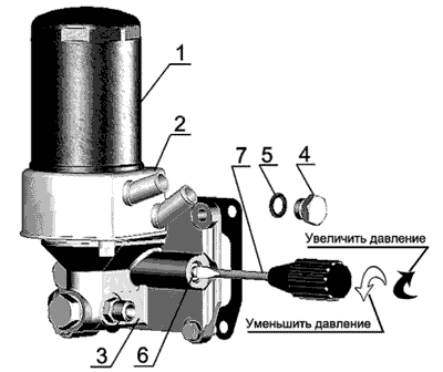
1 - filtri i vajit; 2 - shkëmbyes nxehtësie me vaj të lëngshëm; 3 - strehimi i filtrit të vajit; 4 - priza e valvulës së uljes së presionit; 5 - shtrimi i tapës; 6 - priza rregulluese; 7 - kaçavidë.
Figura 16. Rregullimi i presionit
KONTROLLIMI I NIVELIVE TË VAJIT NË KALIMIN NAFIZEL
Kryeni kontrollin çdo ndërrim përpara se të ndizni naftën duke përdorur një matës vaji të vendosur në bllokun e motorit me naftë.
Niveli i vajit duhet të jetë midis shenjës së poshtme dhe të sipërme të matësit të vajit në përputhje me Figurën 17.
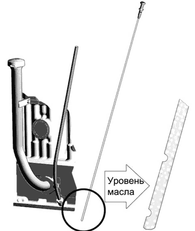
Figura 17- Kontrollimi i nivelit të vajit në karterin e motorit me naftë.
Kontrolli duhet të bëhet jo më herët se 3-5 minuta pas ndalimit të motorit me naftë, kur vaji derdhet plotësisht në kavilje.
Ndalohet funksionimi i motorit me naftë me nivelin e vajit në kavilje nën shenjat e poshtme dhe të sipërme në matësin e vajit.
NDRYSHO VAJIN NË kaviljen me naftë.
Ndryshoni vajin në karterin e motorëve me naftë çdo 10 mijë kilometra. dhe në rastet e përdorimit të vajrave ose karburanteve të dyfishta me përmbajtje të lartë squfuri - çdo 5 mijë km vrapim. Kullojeni vajin e përdorur vetëm nga një motor i ngrohtë me naftë. Për të kulluar vajin, hiqni spinën e gropës së vajit. Pasi të jetë kulluar i gjithë vaji nga karteri, vidhosni spinën përsëri në vend. Mbushni motorin me naftë me vaj përmes tubit të mbushësit të vajit deri në nivelin e shenjës së sipërme në matësin e vajit.
Mbushni gropën e vajit vetëm me vajin e rekomanduar nga ky manual për periudhën e funksionimit.
ZËVENDËSIMI I FILTERIT TË VAJIT
Ndryshoni filtrin e vajit çdo 10 mijë km lëvizje ose sipas rezultateve të diagnostikimit të sistemit "COMMON RAIL" në përputhje me Figurën 18 njëkohësisht me ndryshimin e vajit në kaviljen e motorit me naftë në sekuencën e mëposhtme:
- Zhvidhosni filtrin FM 009-1012005 ose M5101 nga bashkimi 3 duke përdorur çelës i veçantë ose mjete të tjera të improvizuara;
- vidhos në bashkim filtër i ri FM 009-1012005 ose M5101.
Kur instaloni filtrin në montim, lubrifikoni copë litari 4 me vaj motori.
Pasi copë litari të prekë sipërfaqen mbështetëse të kutisë së filtrit 1, kthejeni filtrin 1 në 1,5 rrotullime më shumë. Instaloni filtrin në trup vetëm me forcën e dorës.
Në vend të filtrit FM 009-1012005 dhe M5101, lejohet instalimi i fishekëve të filtrit jo të ndashëm: mod. X149 nga AC Lelko (Francë), mod. L37198 nga Purolator (Itali) dhe kompani të tjera me anti-kullues dhe valvulat e anashkalimit me dimensionet kryesore:
- diametri - 95 -105 mm;
- lartësia - 140 -160 mm;
- fije - ¾ "-16UNF.
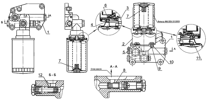
1 - strehimi i filtrit; 2 - shkëmbyes nxehtësie me vaj të lëngshëm (LHMT); 3 - montim; 4 - copë litari filtri; 5 - copë litari e shtresës së lëngshme metalike; 6 - valvul kundër kullimit; 7 - valvul anashkalimi; 8 - valvul sigurie; 9 - prizë për kullimin e ftohësit; 10 - unazë vulosëse; 11 - Valvula e sigurisë LMT: 12 - valvula reduktuese e presionit.
Figura 18 - Opsionet për instalimin e një filtri vaji pa bërthamë metalike të lëngshme dhe me karburant metalik të lëngshëm në motorët me naftë D-245E3