Pezullimi i rrotave të pasme i varur, pasi të dy rrotat janë të lidhura me trupin nga rrezja e boshtit të pasmë, e cila është e lidhur me trupin me katër shufra gjatësore dhe një tërthor. Shufrat gjatësore transmetojnë shtytje dhe forcat e frenimit nga rrotat në trup, dhe shiriti tërthor e mban trupin nga zhvendosja anësore. Rrezja e mbledhur me shufrat përbëjnë udhëzuesin e pezullimit.
| oriz. 1 |
Të dy shufrat gjatësore dhe tërthor janë të lidhur në mënyrë pivotale me njërin skaj në kllapat e trupit, dhe tjetri me kllapat e trarëve të boshtit të pasmë. Çdo shufër është bërë nga tub çeliku, në skajet e rrafshuara të të cilave janë ngjitur kokat. Kokat e shufrave kanë vrima të ngushta në të cilat shtypet mentesha prej gome-metali. Lidhjet e menteshave janë të njëjta në dizajn, ndryshojnë vetëm në madhësi. Çdo menteshë përbëhet nga një tufë gome, në vrimën e së cilës është instaluar mëngë metalike nëpër të cilën kalon buloni i shufrës. Kokat e përparme të shufrave gjatësore janë të lidhura me arra vetë-mbyllëse në kllapat e trupit. Kokat e pasme të këtyre shufrave, si dhe kokat e shufrave gjatësore më të ulëta, janë të lidhura me bulona, arra dhe rondele me kyç. Kllapat për lidhjen e kabllit janë ngjitur në shufrat më të ulëta gjatësore frenave parkimi.
Kur shtrëngoni arrat për fiksimin e shufrave, sigurohet një përshtatje e ngushtë e ndarësve në faqet e kllapave, gjë që nuk lejon që ndarësit të rrotullohen në bulonat e fiksimit. Tufat e gomës gjithashtu nuk mund të rrotullohen në kokat e shufrave, pasi ato kanë një përshtatje të ngushtë në to. Për të përjashtuar veshin e parakohshme varet e shufrave, ato shtrëngohen me një çift rrotullues prej 80 Nm (8 kgf-m) me një ngarkesë që siguron një distancë prej 125 mm nga shtresa e trarit të boshtit të pasmë në pjesën anësore të trupit.
Kur trupi ose rrezja e boshtit të pasmë lëkundet, lëkundja e shufrave ndodh për shkak të deformimit elastik të tufave pa rrëshqitjen e tyre. Tufat prej gome sigurojnë funksionim të qetë të pezullimit dhe nuk kërkojnë lubrifikim.
Elementi elastik i pezullimit janë burimet e instaluara midis trupit dhe rrezes së boshtit të pasmë. Fundi i poshtëm i pranverës ngjitet në kupën e poshtme të mbështetjes përmes një copë litari izoluese plastike. Kupa mbështetëse është ngjitur në rreze të boshtit të pasmë. Fundi i sipërm i pranverës mbështetet në kupën e sipërme mbështetëse të ngjitur në trup. Një copë litari gome është instaluar midis kupës mbështetëse dhe pranverës, e vendosur në një kafaz të vulosur çeliku. Mbulesat izoluese zvogëlojnë transmetimin e zhurmës dhe dridhjeve nga bartësi i boshtit të pasëm në trup.
Burimet e pezullimit të pasmë nën një ngarkesë prej 2950 N (295 kgf) ndahen në dy grupe: A - gjatësi mbi 273 mm, B - gjatësi e barabartë ose më pak se 273 mm. Burimet e grupit A janë shënuar me bojë të verdhë jashte kthehet, dhe grupi B është i gjelbër.
Burimet e grupit A duhet të instalohen në të dy pezullimet. Në raste të jashtëzakonshme, lejohet instalimi i burimeve të grupit B në pezullimin e pasmë, por vetëm burimet e grupit A duhet të instalohen në pezullimin e përparmë.
Pajisja e pezullimit të shuarjes përbëhet nga dy amortizues hidraulikë me veprim të dyfishtë. Çdo amortizues është i lidhur me një kokë në kllapën e trupit, tjetra në kllapën e trarëve të boshtit të pasmë. Kokat e amortizatorëve secila kanë nga dy tufa gome. Në kokën e poshtme, tufat e çelikut kalojnë nëpër vrimën në tufat e gomës, të cilat janë kapur midis dy rondele çeliku.
Kur pezullimi dridhet, varen e amortizatorëve deformohen në mënyrë elastike dhe, si nyjet e tjera të menteshave të këtij lloji, nuk lubrifikohen.
Udhëtimi lart i trarit të boshtit të pasmë është i kufizuar nga dy tamponë kryesorë të ngjeshjes dhe një shtesë. Tamponi kryesor i ngjeshjes ndodhet brenda pranverës dhe është i siguruar me një thith kërpudhash në kupën e sipërme mbështetëse. Tamponi shtesë fiksohet në të njëjtën mënyrë në një kllapa që është ngjitur në pjesën e poshtme të trupit. Gjatë ngjeshjes, tamponët kryesorë qëndrojnë kundër gotave të poshtme të mbështetjes, një shtesë kundër platformës së rrezes së boshtit të pasmë. Udhëtimi i ngjeshjes së pezullimit është 75 mm dhe tërheqja është 135 mm.
Krahu i rrotullimit të makinës së rregullatorit të presionit është i lidhur në mënyrë të pivotshme në kllapën e rrezes së boshtit të pasëm përmes raftit. Mbështetësit për levën 31 janë: nga njëra anë, një kafaz me një mëngë mbështetëse, të fiksuar në pjesën kryq të dyshemesë së trupit, nga ana tjetër, një bosht që është instaluar në vrimat e prizave të strehimit të rregullatorit të presionit 27. Një krah i shkurtër levë kalon nëpër vrimën radiale të boshtit. Për të rregulluar këtë krah levë, përdoret një pllakë, përmes vrimës së së cilës kalon leva, dhe pllaka vetë është e fiksuar në fund të boshtit 29.
Me një lidhje të tillë të pjesëve, leva rrotullohet së bashku me boshtin dhe pllakën në lidhje me vrimat e boshtit. Zgavra e rregullatorit të presionit është e mbyllur me një mbulesë mbrojtëse prej gome.
Pezullimi i rrotave të pasme të makinave VAZ është i unifikuar për të gjitha modelet, me përjashtim të atyre me rrota të përparme. Përveç kësaj, pezullimi i pasmë Makinat "universale" janë të pajisura me burime më të forta.
Në makinë, përdoren disqe, rrota të falsifikuara me madhësi të buzës, të cilat janë bashkangjitur me katër bulona: përpara në shpërndarësin e rrotave, prapa në fllanxhën e boshtit të boshtit. Për përqendrimin e diskut të rrotave në lidhje me vrimat për bulonat në shpërndarës rrota e përparme dhe dy kunja udhëzuese janë të dehur në boshtin e boshtit, të cilat, kur montojnë timonin, futen në vrimat e diskut. Kunjat udhëzues bashkojnë njëkohësisht diskun e frenave dhe unazën e tij të presionit në shpërndarësin e rrotave të përparme, dhe daulle e frenave në fllanxhën e boshtit të boshtit.
Në pjesën periferike të diskut, në kufi me buzën, katër dritare të zgjatura janë vulosur për ventilimin e frenave. Një buzë e profilit të thellë me një zakon asimetrik për gomën është ngjitur në vend në anën e buzës së rrotës. Në buzë ka një vrimë për valvulën e dhomës, dhe në pjesën e poshtme të prerjes së buzës ka dimensione në inç (5J - 13), prodhuesi (VAZ) dhe muaji dhe viti i prodhimit (në numër). Goma radiale me dimensione 175 / 70R-13 (modeli IN-25) ose 165 / 80R-13 (modeli MI-166). Shifra e parë tregon gjerësinë e gomës në mm (175 ose 165), shifrat pas shenjës së fraksionit janë përqindja e lartësisë së profilit në gjerësinë e saj (70 ose 80%), R - struktura radiale goma, kur litarët në pllakat e kufomës janë rregulluar në mënyrë radiale përgjatë profilit të gomave, nga një rruazë në tjetrën, 13 diametri i uljes goma ne inç. Nëse shkronja S futet në shënimin e gomave, atëherë ajo tregon shpejtesi maksimale për këtë gomë (180 km / orë).
Presioni i ajrit në goma me madhësi 175 / 70R-13 duhet të jetë 1.7 kgf / cm 2 për rrotat e përparme, 2.0 kgf / cm 2 për rrotat e pasme dhe 1.6 kgf / cm për goma me madhësi 165 / 80R-13, respektivisht 2, dhe 1.9 kgf / cm 2
Mosbalancimi i gomave dhe rrotave nuk duhet të kalojë 2600 g / mm. Mosbalancimi kontrollohet në stenda speciale dhe eliminohet duke balancuar peshat, të cilat mbahen në buzë nga burime të veçanta.
Çift rrotullues nga transmetim kardan transmetohet në rrotat e drejtimit të automjetit përmes drejtimit përfundimtar, boshteve diferenciale dhe boshtore. Këta mekanizma janë instaluar në boshtin e pasëm të makinës, i cili përbëhet nga dy pjesë themelore: rrezja 13 dhe strehimi 24 i kutisë së shpejtësisë së boshtit të pasmë. Rrezja e boshtit të pasëm 13 përbëhet nga dy gëzhoja të stampuara të salduara me qepje gjatësore. Dy fllanxha çeliku 10 janë ngjitur në skajet e zorrëve, në të cilat vendet për kushinetat 8 dhe vulat 11 të boshteve të boshtit janë përpunuar. Nga faqja fundore në fllanxha ka vrima për bulonat e fiksimit të mburojave 40 të mekanizmave të frenave të rrotave. Të njëjtat bulona me arra fiksojnë devijuesin e vajit 3 dhe pllakën 39, e cila mban boshtin e boshtit duke mbajtur në sediljen e fllanxhës.
Pllaka mbajtëse e boshtit të boshtit dhe deflektori i vajit janë të dehur së bashku përmes një copë litari. Në skajet e rrezes së boshtit të pasmë, saldohen gota mbështetëse të burimeve të pezullimit të pasmë dhe kllapa për bashkimin e shufrave dhe amortizatorëve të pezullimit. Në pjesën e mesme, rrezja zgjerohet dhe ka një hapje përmes, në anën e pasme të së cilës një mbulesë e stampuar është ngjitur me një vrimë mbushëse vaji (në të njëjtën kohë një kontroll), e mbyllur me një prizë, e vendosur në të. Kutia 24 e kutisë së shpejtësisë së boshtit të pasmë është e fiksuar në skajin e përparmë të përpunuar të hapjes. Një frymëmarrës 19 me një valvul me pranverë është i dehur në rreze nga lart. Përmes frymëmarrjes, zgavra e rrezes komunikon me atmosferën, e cila përjashton një rritje të presionit në zgavrën e rrezes dhe hyrjen e ujit dhe papastërtisë në boshtin e pasmë kur kapërceni barrierat e ujit... Brenda rrezes, 15 udhëzues aksesh janë ngjitur për të lehtësuar instalimin e boshteve të boshtit kur montoni boshtin e pasmë. Në pjesën e poshtme të rrezes ka një vrimë të kullimit të vajit. Shtë mbyllur me një prizë me një magnet. Pajisja kryesore përbëhet nga një palë ingranazhe me pjerrësi 33 dhe 21, raport që është 4.1 (numri i dhëmbëve në ingranazh është 21 41, dhe në ingranazhin 33 10).
Ingranazhet kanë një përfshirje hipoide, në të cilën boshti i ingranazhit 33 është zhvendosur në lidhje me boshtin e ingranazhit 21, domethënë, akset e tyre nuk ndërpriten, por ndërpriten. Ingranazhet e tilla kanë një formë dhëmbësh komplekse që lejon dhëmbë të shumtë të përfshihen njëkohësisht dhe pa probleme. Kjo zvogëlon ngarkesën në secilin dhëmb, rrit qëndrueshmërinë e punës veshje kryesore dhe lejon të transmetohet më shumë çift rrotullues. Sidoqoftë, një transferim i tillë kërkon vaj special(TAD17i) me aditivë të presionit ekstrem. Pajisja 33 është montuar në dy kushineta rrotulluese të ngushta 27, midis unazave të brendshme të të cilave ndodhet një mëngë ndarëse 26. mbajtja e brendshme dhe një unazë rregulluese 25 është instaluar me fundin e ingranazhit, trashësia e të cilit është në intervalin nga 2.55 në 3.35 mm çdo 0.05 mm. Shtatëmbëdhjetë madhësi të unazës rregulluese ju lejojnë të rregulloni me saktësi pozicionin relativ të makinës dhe ingranazhet e drejtuara, duke siguruar lidhjen e saktë të dhëmbëve të tyre. Një fllanxhë 30 është vendosur në skajin e ingranazhit të ingranazhit 33, i cili është i lidhur me një arrë vetë-mbyllëse 31. Skaji i punës i gjëndrës 28 shtypet kundër sipërfaqes cilindrike të fllanxhës.
Isshtë i mbrojtur nga dëmtimi nga një deflektor i papastërtisë 29. Një defektor vaji 32 është kapur midis mbajtëses së rrotullës dhe fllanxhës. Për të kufizuar lëvizjen aksiale të shtyllës së drejtimit nën ngarkesa pune dhe për të siguruar funksionim të qetë dhe të qëndrueshëm të ingranazhit kryesor , vendoset një ngarkesë paraprake në kushinetat me majë 27. Ai rregullohet duke shtrënguar arrë 31 në një deformim të caktuar të mëngës ndarëse 26. Para -ngarkesa përcaktohet nga momenti i rezistencës ndaj kthimit të ingranazhit. Gear 21 është bërë në formën e një unaze të dhëmbëzuar, e cila është e lidhur në fllanxhën e kutisë diferenciale. Së bashku me kutinë diferenciale, ingranazhi rrotullohet në dy kushineta rrotulluese të ngushta 17. Ato janë instaluar në prizat e ndara të kaviljes 24, të cilat kanë mbulesa të ndashme 18. Ngarkesa paraprake në kushinetat diferenciale, si dhe hapësira anësore në rrjetëzim e ingranazheve përfundimtare të drejtimit, rregullohet me arra -16. Pozicioni i arrës është i fiksuar nga një pllakë 44, e cila është ngjitur në kapakun mbajtës 18.
Diferenciali është një konike dy satelitore. Ai përbëhet nga dy satelitë të vendosur në një bosht të përbashkët 34, dy ingranazhe anësore 23 dhe një kuti diferenciale. Boshti ndodhet në vrimat e kutisë diferenciale dhe mbahet që të mos bjerë nga ingranazhi 21. i cili mbulon vrimën në kuti. Sipërfaqja hemisferike e satelitëve mbështetet në hemisferën e kutisë diferenciale. Satelitët janë në angazhim të vazhdueshëm me ingranazhet gjysmë-boshtore 23, rripat cilindrikë të të cilëve hyjnë në vrimat e kutisë diferenciale dhe janë mbështetëset e tyre. Rondelet mbështetëse 35 janë instaluar midis skajeve të ingranazheve gjysmë-boshtore dhe kutisë diferenciale. Gjysmë-boshti është bërë integral me fllanxhën, në të cilën daulle e frenave dhe disku i rrotës së pasme janë ngjitur me bulona 1. Fundi i brendshëm i gjysmë-boshtit është i lidhur me shpinë me ingranazhin gjysmë-boshtor 23, i cili mbështet skajin e brendshëm të gjysmë-boshtit. Jashtë, gjysmë-boshti mbështetet në një mbajtës topi 8, i cili shtrëngohet në gjysmë-boshtin midis shpatullës së tij dhe unazës mbyllëse 9. Unaza shtypet në gjysmë-bosht në një gjendje të nxehtë në 300 C.
Kushineta e boshtit të boshtit vuloset nga brenda me një vulë vaji 11, nga jashtë nga një unazë gome e kapur midis mburojës dhe fllanxhës së trarit të boshtit të pasmë. Kushineta është e fiksuar në sediljen e rrezes së boshtit të pasëm me një pllakë 39, e cila, së bashku me deflektorin e vajit 3 dhe mburojën e frenave 40, është ngjitur në fund të rrezes së boshtit të pasmë. Për të zvogëluar gjasat që vaji të hyjë në mekanizmin e frenave të rrotave të pasme në rast të dëmtimit të vulës së vajit 11, brazdat bëhen në boshtin e boshtit dhe është instaluar një deflektor vaji 3. Për të hyrë në arrat e bulonave që sigurojnë deflektori i vajit 3, mburoja 40 dhe pllaka 39. ka dy vrima në boshtin e boshtit për të kaluar çelësin e përfundimit.
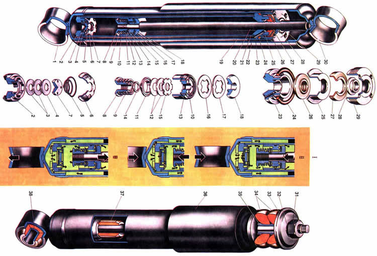
Skema e boshtit të pasëm VAZ 2107
1. Rrufeja e fiksimit të daulles së frenave të një rrote, 2. Një kunj udhëzues; 3. Shufra e naftës e mbajtëses gjysmë-boshtore; 4. Daulle e frenave; 5. Unaza e daulles së frenave prej gize; 6. Cilindër rrota frena e pasme; 7. Lidhja për gjakderdhjen e makinës mekanizmi i frenimit; 8. Mbajtës gjysmë boshtor; nëntë Unazë mbyllëse duke mbajtur; 10. Fllanxha e rrezes së boshtit të pasmë: 11. Vula e vajit Semiaxis; 12. Mbështetni kupën e pezullimit të pranverës; 13. Rrezja e boshtit të pasëm; 14. Kllapa për shiritin e sipërm të pezullimit; 15. Udhëzues gjysmë boshtor; 16. Arrë e kushinetës diferenciale; 17. Kushineta diferenciale e kutisë; 18. Mbulesa e mbajtësit të kutisë diferenciale; 19. Frymëmarrësi; 20. Sateliti i diferencialit; 21. Rrota e ingranazhit të drejtuar të transferit kryesor; 22. Boshti i boshtit të majtë; 23. Pajisje gjysmë boshtore; 24. Rasti i zvogëlimit të boshtit të pasmë; 25 Unaza rregulluese veshje me makinë; 26. Mëngë me hapësirë mbajtëse; 27. Kushineta e ingranazheve të drejtimit; 28. Vula e vajit të ingranazheve të drejtimit; 29. Deflektor i vulës së vajit; 30. Flanxhë-prizë universale e përbashkët; 31. Arrë; 32. Deflektor vaji; 33. Rrota e ingranazheve kryesore të transferit kryesor; 34. Boshti i satelitëve; 35. Rondele mbështetëse të ingranazheve gjysmë boshtore; 36. Kuti diferenciale; 37. Boshti i boshtit të djathtë; 38. Kllapa për fiksimin e pjesëve të pezullimit; 39. Pllakë shtytëse me gjysmë bosht; 40. Mburoja e frenave të pasme; 41. Këpucë e frenave të pasme; 42. Rreshtimi i fërkimit: 43. Fllanxha e boshtit; 44. Pllakë ndalimi; 45. Boloni mbajtës i kapakut të kushinetës.
Pezullimi i përparmë VAZ 2107
Lidhja lidhëse midis rrotave dhe trupit është pezullimi i përparmë dhe i pasëm i automjetit. Përmes tyre, forcat që veprojnë në rrota transmetohen në trup. Elementet e pezullimit zbusin ngarkesat, zvogëlojnë dridhjet e trupit, sigurojnë stabilitet të mirë dhe funksionim të qetë të makinës. Këta elementë përfshijnë pajisjen udhëzuese, burimet, amortizuesit dhe stabilizuesin. stabiliteti anësor... Pajisja drejtuese e pezullimit përcakton lëvizjen e rrotës në lidhje me rrugën dhe trupin dhe transferon forcat dhe momentet nga rrota në trup. Kjo pajisje përfshin krahët e sipërm 33 dhe 6 të poshtëm të pezullimit dhe një nyje drejtuese 29 të lidhur në mënyrë pivotale. Krahu i sipërm është i lidhur me një bosht 42 me skajin e përparmë të trupit me anë të varen prej gome-metali. Aksi, i bërë në formën e një rrufe në qiell me një kokë gjashtëkëndësh, kalon nëpër bishtat e levës 33 dhe përmes lidhëses së shiritit të përparmë. Varet e gomës-metalike shtypen në grykët e levës së sipërme, secila prej të cilave përbëhet nga një tufë gome 49 e shtypur midis tufave metalike të brendshme 47 dhe të jashtme 48 me një përshtatje të lartë ndërhyrjeje.
Shkurre e jashtme 48 shtypet në bishtin e levës së sipërme, dhe pjesa e brendshme 47 shtyhet në boshtin 42. Varet është fiksuar në bosht nga një arrë midis raftit të levës së sipërme dhe rondele 50. e levës së sipërme ndodh brenda deformimit të shkurret e gomës 49. Shkurre gome nuk duhet të rrëshqasë në raport me tufat metalike ose një menteshë në bosht dhe në levë. Ky dizajn varet siguron një lidhje të ngushtë midis boshtit dhe krahut të pezullimit. Bashkangjitur në krahun e sipërm të pezullimit me tre bulona mbajtëse sferike 34 ndërtim me një copë. Në strehën mbajtëse ka një mbajtëse 32, baza e së cilës është rrëshirë, dhe sipërfaqja e fërkimit është pëlhurë Teflon, e cila i përshtatet fort sipërfaqes sferike të kunjit 31. Pjesët e bashkimit të topit mbrohen nga ndotja nga një mbulesë e përforcuar me gome 19. Kunja 31 është instaluar në një vrimë të ngushtë nyje drejtuese 29 dhe të fiksuara me një arrë vetë-mbyllëse. Krahu i poshtëm 6 është pezulluar në një bosht 5, i cili është ngjitur në pjesën kryq 46 të pezullimit me dy bulona 7.
Kjo e fundit është e bashkangjitur në pjesët anësore të trupit. Distanca 44 dhe rregullimi i 43 rondele janë instaluar midis boshtit dhe pjesës kryq. Duke ndryshuar numrin e rondeleve 43, këndi gjatësor (pjerrësia e boshtit dhe kamberit) të rrotave të përparme rregullohet. "Varet prej gome-metali të krahut të poshtëm janë të të njëjtit dizajn si krahu i sipërm, ndryshojnë vetëm në madhësia dhe forma e tufave. Lidhja e poshtme e topit është ngjitur në krahun e poshtëm me tre bulona nga poshtë. Dizajni ndryshon nga mbështetja e sipërme. Në strehimin mbështetës ka një kunj 22 me një kokë hemisferike. Një kushinetë 21 me një sipërfaqja hemisferike vendoset në shufrën e kunjit. Një insert 20 i bërë nga gome rezistente ndaj vajit futet në pjesën e poshtme të strehimit me një përshtatje ndërhyrjeje. Në sipërfaqen e tij duke kontaktuar hemisferën e kunjit 22, një shtresë plastike është e vullkanizuar (a përzierje najloni me sulfid molibden). Për shkak të futjes së gomës, boshllëqet midis pjesëve të nyjës së topit zgjidhen dhe mbajtësja 21 shtypet kundër sipërfaqes hemisferike të pjesës së sipërme të trupit mbështetës. Ka një vrimë trupi mbështetës nën të cilin lyhet mentesha.
Shtë mbyllur me një prizë konike. Pjesët e nyjës së topit mbrohen nga ndotja me një mbulesë mbrojtëse 19. Lidhja e poshtme e topit është e lidhur me nyjën drejtuese në të njëjtën mënyrë si ajo e sipërme. Krahu i poshtëm i pezullimit lidhet me kokën e poshtme të amortizuesit me anë të një kllapa 13 dhe një rrufeje 12. Kllapa 13 është ngjitur në krahun e pezullimit me dy bulona I. Shufra e amortizatorit kalon nëpër vrimën në xhamin mbështetës 37 ngjitur në skajin e përparmë të trupit dhe është e siguruar me një arrë. Jastëkët izolues të gomës 38 janë instaluar midis zorrës së amortizatorit dhe xhamit, si dhe midis rondele mbështetëse 39 dhe xhamit. Krahët e pezullimit janë të lidhur në mënyrë pivotale me nyjën e drejtimit 29. Në trungun e së cilës, shpërndarësi i rrotave të përparme 17 është i instaluar. Bashkangjitur në fllanxhën e kyçit të drejtimit janë mbajtësja e montimit të caliperit dhe mbrojtësi i frenave, si dhe krahu i rrotullimit të ingranazheve drejtuese. Elementet elastike të pezullimit janë burimet 8, që punojnë në lidhje me amortizuesit dhe shiritin kundër rrotullimit. Fundi i sipërm i pranverës së pezullimit kalon nëpër kupën mbështetëse 41 me një copë litari gome 40 në anën e përparme të trupit. Fundi i poshtëm i pranverës ngjitet në kupën mbështetëse 14 të krahut të poshtëm të pezullimit.
Burimet e pezullimit të përparmë renditen sipas gjatësisë nën një ngarkesë prej 4350 N (435 kgf) në grupet A dhe B dhe, për t'i dalluar ato, shënohen: grupi A me një shirit të verdhë, grupi B - me një të gjelbër. Shiritat aplikohen me bojë në pjesën e jashtme të kthesave. Udhëtimi lart i rrotës së përparme është i kufizuar nga ndalimi i levës së sipërme 33 në tamponin e gomës 35 të goditjes së ngjeshjes, të instaluar me boshtin e tij në vrimën e kllapës 36, e cila është ngjitur në shiritin e përparmë. Shiriti kundër rrotullimit zvogëlon rrotullimin anësor të trupit kur automjeti po kthehet. Shtë një shirit 3 i bërë prej çeliku pranveror. Skajet e lakuara të shiritit janë bashkangjitur në kllapat e krahëve të poshtëm të pezullimit me kapëset 9 përmes jastëkëve prej gome 2, të cilat vendosen në skajet e shiritit. Pjesa e mesme e shufrës është ngjitur me kllapa 1 me jastëkë gome 2 në pjesët anësore të trupit. Kur trupi rrotullohet anash, ngarkesa në një pezullim të rrotave rritet, nga ana tjetër zvogëlohet; në këtë rast, shiriti i stabilizatorit kthehet dhe fillon të punojë si një torus.
Duke u rrotulluar, ai transferon ngarkesën nga një pezullim në tjetrin, duke niveluar pozicionin e trupit. Shpërndarësi i rrotave të përparme 17 është montuar në boshtin e nyjës drejtuese 26 në dy kushineta rrotulluese 18, të cilat janë shtrënguar nga një arrë rregulluese. Një rondele me mustaqe është instaluar midis arrës dhe kushinetës së jashtme, e cila përshtatet në brazdën e trungut. Tendili mban rondele nga rrotullimi kur shtrëngoni arrë. Drejtimi i fillit në arra është i ndryshëm: në trunin e majtë - fije e djathtë, në të djathtë - në të majtë. Arrë është fiksuar në skajin e filetuar të trunnionit duke shtypur jakën cilindrike në dy brazdat e trunnionit. Një gjëndër vetë-shtrënguese 27 është instaluar në anën e brendshme në folenë shpërndarëse, buza e punës e së cilës mbulon sipërfaqen e lëmuar të brezit të revistës. Jashtë, zgavra e brendshme e shpërndarësit mbrohet nga një kapak 23 i shtypur në gropën e shpërndarësit. Disku i frenave dhe unaza e presionit janë ngjitur në fllanxhën e shpërndarësit me dy kunja udhëzues. Disku i rrotës përqendrohet në kunjat udhëzuese, i cili është ngjitur në shpërndarës me katër bulona. " Kënd tërthor pjerrësia (n) nuk është e rregullueshme.
Skema e pezullimit të përparmë VAZ 2107

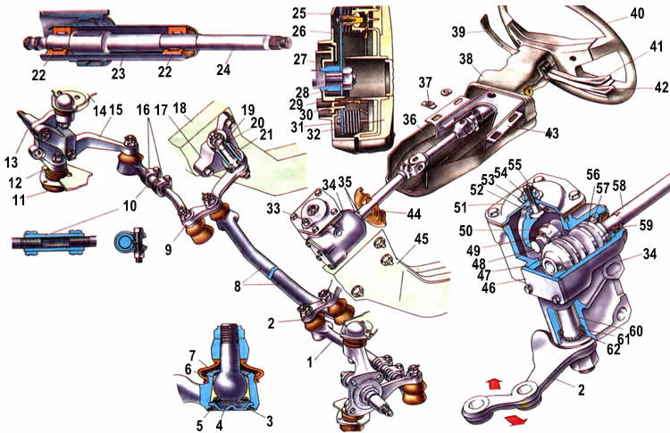
1. Kllapa për lidhjen e shiritit të stabilizatorit në anën anësore të trupit; 2. Jastëk i shiritit të stabilizatorit; 3. Shirit i shiritit kundër rrotullimit; 4. Spar trupi: 5. Boshti i krahut të poshtëm; 6. Krahu i poshtëm i pezullimit; 7. Vidhat e boshtit të krahut të poshtëm në anën kryq të pezullimit; 8. Pranvera e pezullimit; 9. Kapëse për fiksimin e shiritit të stabilizatorit; 10. Amortizues: II. 11. Mbërthimi i bulonës në kllapën e amortizatorit në krahun e poshtëm; 12. Rrufeja e montimit të amortizuesit; 13. Kllapa për lidhjen e amortizatorit në krahun e poshtëm; 14. Kupa pranverore më e ulët mbështetëse; 15. Zgjedhja e futjes së mbështetësit të poshtëm; 16. Mbulesa mbajtëse e kunjit të topit të poshtëm; 17. Qendër e rrotave të përparme; 18. Kushinetat e shpërndarësit të rrotave të përparme; 19. Mbulesa mbrojtëse për kunjin e topit; 20. Futja e kafazit të kunjit të topit të poshtëm: 21. Mbajtja e kunjit të topit të poshtëm; 22. Kunja e topit e mbështetëses së poshtme: 23. Kapaku i shpërndarësit: 24. Arrë rregulluese; 25. Rondele: 26. Boshti i cungut; 27. Vula e vajit shpërndarës: 28. Disku i frenave; 29. Nyja e drejtimit: 30. Kufizuesi i rrotullimit të rrotave të përparme; 31. Kunja e topit të mbështetësit të sipërm; 32. Kushineta e topit të sipërm: 33. Krahu i sipërm i pezullimit; 34. Mbulesa mbajtëse e kunjit të topit të sipërm; 35. Tampon i goditjes në shtypje; 36. Kllapa tampon e goditjes në kompresion; 37. Mbështetës amortizuesin e qelqit; 38. Jastëk për fiksimin e shufrës së amortizuesit; 39. Rondele për jastëkun e shufrës thithëse të goditjes: 40. Rondele izoluese të sustës pezulluese: 41. Kupa e sustës së sipërme të mbështetjes së sipërme; 42. Boshti i krahut të sipërm të pezullimit; 43. Rregullimi i rondeleve; 44. Rondele me hapësirë; 45. Kllapa për fiksimin e pjesës kryq në anën anësore të trupit; 46. Anëtar kryq i pezullimit të përparmë; 47. Mëngë e brendshme e menteshës: 48. Mëngë e jashtme e menteshës; 49. Shkurre gome me mentesha: 50. Rondele për futjen e menteshave; 51. Camber (b) dhe këndi pjerrësia anësore akset rrotulluese (g); 52. Këndi gjatësor i boshtit të rrotullimit të rrotës (a); 53. Gishti i këmbës i rrotave të përparme (L2-LI).
Pezullimi i pasëm VAZ 2107
Pezullimi i rrotave të pasme është i varur, pasi të dy rrotat janë të lidhura me trupin nga rrezja e boshtit të pasmë, e cila është e bashkangjitur në trup me katër shufra gjatësore dhe një tërthor. Shufrat gjatësore transmetojnë forcat shtytëse dhe frenuese nga rrotat në trup, dhe shufra tërthore e mban trupin nga zhvendosja anësore. Rrezja e mbledhur me shufrat përbëjnë udhëzuesin e pezullimit. Të dy shufrat gjatësore dhe tërthor janë të lidhur në mënyrë pivotale me njërin skaj në kllapat e trupit, dhe tjetri me kllapat e trarëve të boshtit të pasmë. Çdo shufër është bërë nga një tub çeliku, në skajet e rrafshuar të të cilit janë ngjitur kokat. Kokat e shufrave kanë vrima të ngushta në të cilat shtypet mentesha prej gome-metali. Lidhjet e menteshave janë të njëjta në dizajn, ndryshojnë vetëm në madhësi. Çdo menteshë përbëhet nga një tufë gome 24, në vrimën e së cilës është instaluar një tufë metalike 23, përmes vrimës së së cilës kalon një rrufe për fiksimin e shufrës. Kokat e përparme të shufrave gjatësore janë të lidhura me arra vetë-mbyllëse në kllapat e trupit. Kokat e pasme të këtyre shufrave, si dhe kokat e shufrave gjatësore më të ulëta, janë të mbërthyera me arra dhe rondele për kyçje. Kllapat e montimit të kabllit të frenave të parkimit janë ngjitur në shufrat më të ulëta gjatësore.
Kur shtrëngoni arrat për fiksimin e shufrave, sigurohet një përshtatje e ngushtë e mëngëve ndarëse 19 dhe 23 në faqet e kllapave, gjë që nuk lejon që mëngët e ndarësit të rrotullohen në bulonat e fiksimit. Tufat e gomës 20 dhe 24 gjithashtu nuk mund të rrotullohen në kokat e shufrave, pasi ato kanë një përshtatje të ngushtë në to. Për të përjashtuar konsumimin e parakohshëm të menteshave të shufrave, ato shtrëngohen me një çift rrotullues prej 80 Nm (8 kgcm) me një ngarkesë që siguron një distancë prej 125 mm nga shtresa e trarëve të boshtit të pasmë në pjesën anësore të trupit. Kur trupi ose rrezja e boshtit të pasmë dridhet, shufrat lëkunden për shkak të deformimit elastik të tufave të gomës pa rrëshqitje. Tufat prej gome sigurojnë funksionim të qetë të pezullimit dhe nuk kërkojnë lubrifikim. Elementi elastik i pezullimit janë burimet 7 të instaluara midis trupit dhe rrezes së boshtit të pasmë. Fundi i poshtëm i pranverës përputhet me kupën e poshtme të mbështetjes 3 përmes një copë litari izoluese plastike 2. Kupa mbështetëse është ngjitur në traun e boshtit të pasmë. Fundi i sipërm i pranverës përputhet me kupën e sipërme mbështetëse 11 të ngjitur në trup. Një copë litari gome 10 është instaluar midis kupës mbështetëse dhe burimit, e vendosur në një kafaz çeliku të stampuar 9. Rondelet izoluese 10 dhe 2 zvogëlojnë transmetimin e zhurmës dhe dridhjeve nga rrezja e boshtit të pasmë në trup.
Burimet e pezullimit të pasmë nën një ngarkesë prej 2950 N (295 kgf) ndahen në dy grupe: A - gjatësi mbi 273 mm, B - gjatësi e barabartë ose më pak se 273 mm. Burimet e grupit A janë shënuar me bojë të verdhë në pjesën e jashtme të kthesave, dhe grupi B - jeshil. Burimet e të njëjtit grup duhet të instalohen në të dy pezullimet. Në raste të jashtëzakonshme, lejohet instalimi i burimeve të grupit B në pezullimin e pasmë, por vetëm burimet e grupit A. duhet të instalohen në pezullimin e përparmë. Pajisja e amortizimit të pezullimit përbëhet nga dy amortizues hidraulikë me veprim të dyfishtë. Çdo amortizues është i lidhur me një kokë në kllapën e trupit, tjetra në kllapën e trarëve të boshtit të pasmë. Dy tufa gome janë instaluar në kokat e amortizatorëve. Në kokën e poshtme, një tufë çeliku kalon nëpër vrimën në tufat e gomës, e cila është e shtrënguar midis dy rondele çeliku. Kur pezullimi dridhet, varen e amortizatorëve deformohen në mënyrë elastike dhe, si nyjet e tjera të menteshave të këtij lloji, nuk lubrifikohen. Udhëtimi përpjetë i rrezes së boshtit të pasmë është i kufizuar nga dy mbrojtës kryesorë 4 të goditjes së ngjeshjes dhe një shtesë 17. Tamponi kryesor i goditjes së ngjeshjes ndodhet brenda pranverës dhe sigurohet nga një thithë kërpudhe në kupën e sipërme mbështetëse. Tamponi shtesë fiksohet në të njëjtën mënyrë në një kllapa që është ngjitur në pjesën e poshtme të trupit. Gjatë ngjeshjes, tamponët kryesorë qëndrojnë kundër gotave të poshtme mbështetëse 3, një shtesë kundër platformës së trarit të boshtit të pasmë. Udhëtimi i ngjeshjes së pezullimit është 75 mm dhe tërheqja është 135 mm.
Krahu i rrotullimit 31 i drejtuesit të rregullatorit të presionit është i lidhur në mënyrë të pivotshme në kllapën e rrezes së boshtit të pasëm përmes shiritit 12. Mbështetësit për levën 31 janë: nga njëra anë, zgjedha 32 me mëngën mbështetëse 33, të bashkangjitur në pjesën kryq të dyshemesë së trupit, dhe nga ana tjetër, boshti 29, i cili është i instaluar në vrimat e grykave të trupit të rregullatorit të presionit 27. Krahu i shkurtër i levës 31 kalon nëpër vrimën radiale të boshtit 29. Për të rregulluar këtë krah levë, përdoret një pllakë, përmes vrimës së së cilës kalon leva 31, dhe vetë pllaka është me bulona deri në fund të boshtit 29. Me këtë lidhje të pjesëve, leva 31 rrotullohet së bashku me boshtin dhe pllakën në raport me vrimat e boshtit. Zgavra e rregullatorit të presionit mbyllet me një mbulesë mbrojtëse prej gome 28.
Skema e pezullimit të pasëm VAZ 2107

1. Shufra gjatësore më e ulët; 2. Rondele izoluese të sustës së poshtme të pezullimit; 3. Kupa pranverore më e ulët mbështetëse; 4. Tampon i goditjes në kompresion; 5. Rrufeja e fiksimit të shufrës së sipërme gjatësore; 6. Kllapa për fiksimin e shufrës së sipërme gjatësore; 7. Pranvera e pezullimit; 8. Mbështetje tampon e goditjes në kompresion; 9. Unaza e sipërme e copëzës së pranverës; 10. Rondelë pranverore izoluese e sipërme; 11. Kupa e pezullimit të pranverës së sipërme; 12. Rafti i levës së drejtimit të rregullatorit të presionit; 13. Mbulesa gome e levës së drejtimit të rregullatorit të presionit; 14. Lavatrice e kunjit të montimit të amortizatorit; 15. Mbulesa gome për sytë e amortizatorëve; 16. Kllapa e montimit të amortizatorit të pasëm; 17. Tampon shtesë i goditjes së kompresimit; 18. Rondele me hapësirë; 19. Mëngë ndarëse të shufrës gjatësore të poshtme; 20. Bush gome të shufrës së poshtme gjatësore; 21. Kllapa për fiksimin e shufrës së poshtme gjatësore; 22. Kllapa për lidhjen e shufrës së sipërme gjatësore në traun e urës; 23. Mëngë ndarëse për shufra tërthor dhe gjatësor; 24. Llastik gome i shufrave të sipërme gjatësore dhe tërthore; 25. Amortizues i pasmë; 26. Kllapa për fiksimin e shufrës tërthore në trup; 27. Rregullatori i presionit të frenave; 28. Mbulesa mbrojtëse për rregullatorin e presionit; 29. Boshti i levës së drejtimit të rregullatorit të presionit; 30. Vidhat e fiksimit të rregullatorit të presionit; 31. Leva e drejtimit të rregullatorit të presionit; 32. Mbajtësja e mëngës mbështetëse me levë; 33. Mëngë mbështetëse; 34 Shirit i kryqëzuar; 35. Pllaka mbështetëse e kllapës së montimit të shufrës tërthore.
Amortizues VAZ 2107
Amortizuesit e pezullimeve të përparme dhe të pasme ndryshojnë në madhësi, metoda e bashkimit të pjesës së sipërme, prania e një tamponi 37 në amortizator para e cila kufizon gjatësinë e shufrës gjatë goditjes në prapavijë dhe kështu pengon që rrotat e përparme të lëvizin tepër poshtë kur ngasin në rrugë shumë të pabarabarta. Përveç kësaj, amortizuesit ndryshojnë në parametra karakteristikat e performancës... Sidoqoftë, pjesët kryesore të amortizatorit të përparmë janë të njëjta me ato të pasme, kështu që në të ardhmen, vetëm amortizues i pasmë... Amortizuesi përbëhet nga pjesët kryesore të mëposhtme: një rezervuar me kokën 1, një cilindër pune 21, një valvul ngjeshjeje dhe një shufër 20 të mbledhur me një pistoni dhe valvola, një mëngë udhëzuese 23, një arrë 29, vula dhe një shtresë e jashtme. Vëllimi për lëngu i punës shërben si një cilindër 2-1 dhe një rezervuar 19, i bërë nga një tub. Në pjesën e poshtme të rezervuarit, pjesa e poshtme është e ngjitur, mbi të cilën mbështetet valvula e kompresimit. Në pjesën e sipërme të rezervuarit, një fije është prerë për arrë 29. Jashtë, koka e poshtme e amortizatorit është ngjitur në pjesën e poshtme të rezervuarit. Valvula e kompresimit përbëhet nga një trup 2. disqet 3 dhe 4, një pllakë 7, një sustë 5 dhe një kafaz 6. Trupi i valvulës së kompresimit është sinteruar. Në pjesën e sipërme të saj, një fole e çarë është përpunuar, e mbivendosur nga disqe, të cilat shtypen kundër folesë nga një burim 5 përmes një pllake 7. Fundi i sipërm i burimit përputhet me një zgjedhë 6, e cila vihet në brezin cilindrik të trupi i valvulës. Për të siguruar kalimin e lëngut nga rezervuari 19 në cilindrin 21 dhe mbrapa, një vrimë cilindrike dhe katër brazda vertikale bëhen në pjesën e poshtme të trupit të valvulës afërsisht të njëjtën thellësi me vrimën. Të njëjtat lojëra elektronike gjenden në pjesën e sipërme të trupit të valvulës së ngjeshjes.
Disqet 3 të valvulës së ngjeshjes janë të sheshta, të bëra nga shirit çeliku 0.15 mm të trasha, kanë vrima në qendër për kalimin e lëngut. Në vrimën qendrore të diskut 4 ka një ndërprerje përmes së cilës lëngu mbyten kur shpejtësi të ulët zhvendosjet e pistonit 10. Pllaka 7 ka një zgjatje cilindrike në pjesën e poshtme qendrore, e cila mbivendos vrimën qendrore të disqeve 3 dhe 4, por nuk mbyll mbylljen e mbytjes. Kur mblidhet, formohet një hendek midis tabaka 7 dhe diskut 4 për kalimin e lëngut. Për të njëjtin qëllim, katër nëpër vrima... Zgjedhja 6 ka një fllanxhë dhe një jakë cilindrike, mbi të cilën cilindri 21 është i pajisur fort, i cili siguron ngushtësinë e nevojshme midis valvulës së kompresimit dhe cilindrit. Gjashtë vrima anësore dhe një qendrore për kalimin e lëngut bëhen në sipërfaqen e stampuar të kafazit. Një shufër me një pistoni 10 është instaluar në cilindrin 21, mbi të cilin është montuar një valvul anashkalimi dhe një valvul tërheqëse.
Pistoni ka kanale vertikale të vendosura në dy rrathë; kanalet e secilit rreth lidhen me njëri -tjetrin me një zakon unazor. Kanalet e vendosura më afër qendrës së pistonit bllokohen nga poshtë nga disqet 15 dhe 12 të valvulës së tërheqjes, dhe nga lart - më tej nga qendra me disk 16 valvula e anashkalimit, i ngjeshur nga pranvera 17. Goditja e diskut është e kufizuar nga ndalimi i pranverës kundër diskut 18. Pistoni mbyllet në cilindër me një unazë 13. Disqet e valvulave të zmbrapsjes shtypen në skajin e poshtëm të pistonit nga pranvera 9 përmes diskut 11. Në këtë rast, susta shtyp pjesën e jashtme të disqeve, dhe pjesa e brendshme disqe - 15 dhe 12 shtypet fort kundër pistonit me një arrë 8 të vidhosur në skajin e filetuar të shufrës. Për të mbrojtur disqet e valvulave të zmbrapsjes nga dëmtimi dhe funksionimi i qëndrueshëm i valvulës, një rondele 14 është instaluar midis disqeve dhe arrës. Disku i mbytjes 15 i valvulës së kthimit në diametrin e jashtëm ka gjashtë prerje për kalimin e lëngut me një goditje të qetë të tërheqjes Me Për lëvizjen e drejtuar të shufrës 20 në lidhje me cilindrin, ekziston një mëngë udhëzuese e sinterizuar 23 e instaluar me një jakë cilindrike në një vrimë të kalibruar në cilindër. Mëngë ka një kanal të prirur për të kulluar lëngun që ka kaluar nëpër hendekun midis rrjedhës dhe mëngës udhëzuese përsëri në rezervuar.
Në krye të sediljes së shiritit ka një vulë vaji 26 të bërë prej gome rezistente ndaj vajit. Buzët e punës të kutisë së mbushjes mbulojnë sipërfaqen e kromuar të kërcellit, duke parandaluar daljen e lëngut nga amortizuesi. Kutia e mbushjes, së bashku me unazën 24, e cila vulos hendekun midis mëngës udhëzuese 23 dhe rezervuarit 19, është e ngjeshur nga kafazi 25. Midis kafazit dhe arrës 29, një unazë mbrojtëse e shkrirë 28 dhe një copë litari gome 27 janë unaza mbrojtëse heq papastërtitë nga shufra gjatë ngjeshjes. Funksionimi i amortizatorit. Parimi i funksionimit të amortizatorit bazohet në krijimin e një rezistence të shtuar ndaj lëkundjes së trupit për shkak të rrjedhjes së detyruar të lëngut përmes seksioneve të vogla të rrjedhjes në valvola. Gjatë goditjes së ngjeshjes, kur rrotat e makinës lëvizin lart, amortizuesi është i ngjeshur, domethënë pistoni zbret poshtë dhe zhvendos lëngun nga fundi i cilindrit, pjesë e të cilit, duke kapërcyer rezistencën e pranverës së sheshtë të valvulës së anashkalimit , rrjedh nga hapësira nën-pistoni në hapësirën mbi-pistoni. I gjithë lëngu i zhvendosur nuk mund të kalojë në këtë mënyrë, pasi shufra rrëshqitëse zë një pjesë të vëllimit të lëshuar nga pistoni, prandaj, një pjesë e lëngut, duke u përkulur prapa skajet e brendshme të disqeve të valvulave të ngjeshjes, rrjedh nga cilindri në rezervuar Me Me një goditje të qetë të rrjedhës, forca nga presioni i lëngut do të jetë e pamjaftueshme për të shtrydhur skajet e brendshme të disqeve nga pllaka, dhe lëngu do të kalojë në rezervuar përmes prerjes së diskut të mbytjes 4.
Gjatë tërheqjes, rrotat e makinës, nën veprimin e elementeve elastike të pezullimit, ulen, dhe amortizuesi shtrihet, domethënë pistoni lëviz lart. Në këtë rast, presioni i lëngut krijohet mbi pistonin, dhe vakumi krijohet nën piston. Lëngu nga hapësira e sipërme e pistonit, duke kapërcyer rezistencën e pranverës, përkul skajet e jashtme të disqeve të valvulës së tërheqjes dhe derdhet në pjesën e poshtme të cilindrit. Për më tepër, për shkak të vakumit, një pjesë e lëngut nga rezervuari, duke përkulur skajet e jashtme të disqeve të valvulave të ngjeshjes larg trupit të valvulës, mbush pjesën e poshtme të cilindrit. Me një shpejtësi të ulët pistoni, kur presioni i lëngut është i pamjaftueshëm për të shtrydhur disqet e valvulës së tërheqjes, lëngu përmes ndërprerjeve anësore të diskut të mbytjes 15 do të mbyten, duke krijuar rezistencë ndaj goditjes së zmbrapsjes.
Skema e amortizuesit VAZ 2107
1. Koka e poshtme; 2. Trupi i valvulës së ngjeshjes; 3. Disqet e valvulave të ngjeshjes; 4. Disku i mbytjes së valvulës së ngjeshjes; 5. Pranvera e valvulës së ngjeshjes; 6. Zgjedhja e valvulës së ngjeshjes; 7. Pllaka e valvulave të ngjeshjes; 8. Rrokullisni arrën e valvulës; 9. Rrokullisni pranverën e valvulës; 10. Piston amortizues; 11. Rivendosni diskun e valvulave; 12. Rrokullisni disqet e valvulave; 13. Unaza pistoni; 14. Rondele e arrës së valvulës së tërheqjes; 15. Disku i mbytjes së valvulës së tërheqjes; 16. Pllakë valvulash anashkaluese; 17. Pranvera e valvulës së anashkalimit; 18. Pllakë kufizuese; 19. Rezervuari; 20. Stoku; 21. cilindër; 22. zorrë; 23. Mëngë udhëzuese burimore; 24 Unazë vulosëse rezervuar; 25. Mbajtës i gjëndrës së shufrës; 26. Vula e shufrës; 27. Rondele e unazës mbrojtëse të kërcellit; 28. Unaza mbrojtëse e kërcellit; 29. Arrë rezervuari; 30. Koka e amortizuesit të sipërm; 31. Arrë e montimit të amortizatorit të përparmë; 32. Rondele pranvere; 33. Lavatrice jastëkësh; 34. Jastëkë; 35. Mëngë hapësirë; 36. zorrë e amortizatorit të pezullimit të përparmë; 37. Tampon i kërcellit; 38. Varese gome-metali; 39. Skema e amortizuesit; 40. II. Goditje në ngjeshje; 41. Kursi i tërheqjes.
Drejtues VAZ 2107
Makina përdor një traumatik drejtues me një të ndërmjetme bosht kardan... Në drejtimin, bëhet një dallim midis një ingranazhi drejtues dhe një drejtuesi. Përmes ingranazhit drejtues, fuqia transmetohet nga shoferi në ingranazhin drejtues, dhe ingranazhi drejtues transmeton fuqinë në rrota të drejtueshme... Pajisja drejtuese përbëhet nga veshje krimbi, timoni 40, boshti i përbërë i drejtimit dhe pjesët e tij të fiksimit. Pajisja e krimbave (raporti i ingranazheve 16.4) është e vendosur në një kavilje alumini 34, e cila është ngjitur në anën e majtë të trupit me tre bulona me arra vetë-mbyllëse. Dy vrimat e bulonave të kavanozit janë ovale për tu siguruar instalimi i saktë grup timoni. Me këtë instalim, këndi midis boshtit 58 të krimbit dhe horizontales nuk duhet të kalojë 32, dhe hendeku midis boshtit 58 dhe pedalës së frenave duhet të jetë së paku 5 mm. Një krimb 56 është instaluar në kthesën 34 në dy kushineta kontakti këndore 57. Kushinetat nuk kanë unaza të brendshme. Roli i tyre luhet nga Rutine bërë në skajet e krimbit. Pastrimi në kushinetat e krimbave rregullohet nga ndarësit 47 të instaluar nën kapakun e poshtëm. Në dalje nga kavilja, boshti i krimbave vuloset me një vulë vaji 59.
Në pjesën spline të boshtit të krimbave, bëhet një zakon unazor për bulonën bashkuese të pirunit të përbashkët universal. Në përfshirje me krimbin është një rul me dy kreshta 50, i cili rrotullohet në një bosht 48 në një top me rresht të dyfishtë 49. Skajet e boshtit, pasi shtypet në vrimën e boshtit 62, janë të lidhura duke përdorur ngrohje elektrike , domethënë, kjo lidhje është një-pjesëshe. Boshti bipod me pjesën e tij cilindrike të bluar është instaluar në dy tufa bronzi 60 dhe është vulosur me një vulë vaji 61 në dalje nga kthesa. Bipod 2 futet në vija të ngushta të boshtit të poshtëm në një pozicion të caktuar, kur vija e dyfishtë në bosht është e lidhur me çarë të dyfishtë në vrimën e bipodit. Fejesa palë krimbaështë bërë me një zhvendosje prej 5.5 mm të boshteve të rrotullës dhe krimbave, e cila ju lejon të rregulloni përfshirjen pa rrotullim të rrotullës me krimbin ndërsa ato konsumohen. Kjo sigurohet nga zhvendosja aksiale e boshtit bipod me anë të vidës rregulluese 55. Koka e vidës përshtatet në prerjen në formë T të boshtit bipod së bashku me pllakën 52. e cila siguron përshtatjen e dëshiruar të kokës së vidës. Vidë rregulluese 55 është i dehur në kapakun e sipërm 51. të siguruar nga rrotullimi me një rondele dhe të shtrënguar me një arrë bllokimi.
Kur vidhosni vidën rregulluese në kapak, boshti i bipodit ulet dhe një hendek zgjidhet në përfshirjen e rulit me krimbin. Për të përcaktuar saktësinë e rregullimit të pastrimit në kushinetat e krimbit dhe në përfshirjen e rrotullës me krimbin, përdoret një dinamometër, i cili mat momentin e rezistencës (fërkimit) ndaj kthimit. Në këtë rast, çift rrotullimi i fërkimit të boshtit të krimbave matet së pari pa instaluar boshtin bipod. Duhet të jetë brenda 2050 Nm (2-5 kgssm). Duke përzgjedhur trashësinë e shims 47 set lejimi i kërkuar(moment fërkimi) në kushinetat e krimbave. Pastaj, pas instalimit të boshtit bipod dhe rregullimit të hapësirës në bashkim, çift rrotullimi i fërkimit të krimbit kontrollohet. e cila duhet të jetë e barabartë me 90-120 Nm (9-12 kgssm) kur ktheni boshtin e krimbit me 30 si në të majtë dhe në të djathtë nga pozicioni i mesëm dhe zvogëlohet pa probleme në 70 N cm (7 kgssm) kur ktheheni nga një kënd prej 30 deri në ndalesë. Në skajin e sipërm të kthesës 34 të mekanizmit drejtues dhe në boshtin 58 të krimbit, bëhen shenja (rreziqe) 35. lëvizje e drejtë makinë
Në këtë pozicion, folja e timonit duhet të jetë horizontale. Kjo tregon lidhjen e saktë të boshtit të krimbave me boshtin e ndërmjetëm. Pjesët e ingranazheve të krimbave lubrifikohen me vaj TAD-17i, i cili derdhet përmes vrimës së mbyllur me prizën 33, kapaciteti mbushës 0.215 l. Rrota e bërë nga plastika e përforcuar me një kornizë çeliku. Në shpërndarësin 28 të timonit të rrotave me një zgavër të dyfishtë, dhe në boshtin e sipërm 24 ka spina të dyfishta, gjë që siguron lidhjen e rrotës me boshtin vetëm në një pozicion. Timoni është ngjitur në boshtin 24 me një arrë, e cila, pas shtrëngimit, shpohet jashtë në një pikë. Nga poshtë në shpërndarësin 28, një mbajtëse plastike 29 e pjesës së poshtme unazë rrëshqitëse 27 në të cilën rrëshqet kontakti i ndërprerësit. Ky kontakt është i lidhur me tela në spiralen e stafetës së ndërprerësit sinjal zanor... Mbajtësi 26 i ndërprerësit të sinjalit është ngjitur në shpërndarësin e timonit me vida. Shtë i izoluar nga "masa". Unaza e poshtme e rrëshqitjes 27 është e lidhur me telat 30, grykat 25 prej të cilave janë montuar në çelësin 32 të sinjalit të zërit. Burimet 31 janë instaluar midis ndërprerësit 32 dhe spinës.
Kur shtypni çelësin 32, gërshetat 25 të telave mbyllin unazën e poshtme të kontaktit në tokë, domethënë dredha -dredha e stafetës për ndezjen e sinjalit të zërit. Kur çelësi lëshohet, kontaktet hapen nën veprimin e burimeve 31. Për sigurinë e shoferit, boshti i drejtimit është i ndarë. Përbëhet nga një bosht i sipërm 24 dhe një 36 boshte të ndërmjetme me nyje kardani. Boshti i sipërm rrotullohet në dy kushineta gjilpërë 22 me tufa gome. Kushinetat janë të vulosura në tubin 23 të kllapës 43. Më afër mbështetja e poshtme një unazë me një zakon është ngjitur në bosht 24 pajisje kundër vjedhjes. Boshti i ndërmjetëm në skajet ka dy nyje universale të pandashme në kushinetat e gjilpërës. Pirunët e menteshës kalohen në boshtin 58 të krimbit dhe boshtin e sipërm 24 dhe fiksohen me bulona lidhëse. Kllapa 43 është ngjitur në kllapën e panelit të trupit me katër bulona. për më tepër, kokat e dy bulonave të poshtëm janë të dehur në arrat e salduara të kllapës së panelit dhe janë të përdredhur në momentin e shtrëngimit maksimal.
Pllakat fiksuese 37 janë instaluar nën bulonat e poshtëm, ngurtësia e të cilave është projektuar për një ngarkesë të caktuar. Bulonat e sipërm janë ngjitur dhe kllapa 43 është ngjitur në to me arra me rondele me figura dhe pranverë. Kur makina përplaset me një pengesë, ngarkesa në bulonat e kllapës 43 rritet dhe nën ndikimin e saj skajet e pllakave 37 deformohen. Në këtë rast, kllapa 43 rrëshqet mbi bulonat e fiksimit të përparmë, duke u kthyer në lidhje me bulonat e fiksimit të sipërm, si rezultat i të cilit timoni largohet nga zona e gjoksit të shoferit, gjë që zvogëlon mundësinë e lëndimit serioz. Boshti drejtues është i mbuluar me një shtresë rreshtimi 38. e përbërë nga një pjesë e sipërme dhe e poshtme, e lidhur me vida. Makina drejtuese përfshin: bipodin 2, mesin 8 dhe shufrat anësore 1, krahun e lavjerrësit 9, krahët e lëkundjes 15. Këto pjesë janë të lidhura me nyje topi. Bipod është i lidhur me shufrat e mesme dhe anësore. Ka një ndalesë që kufizon këndin e rrotullimit të rrotave të përparme.
Shtytja e mesme 8 është një copë, në skajet e saj ka çarë për akomodimin e pjesëve të nyjeve të topit. Shufrat anësore janë 1 përbërës. Secila prej tyre përbëhet nga dy skaje të lidhura me njëra -tjetrën me një mëngë rregulluese të filetuar 10. Mëngë është e fiksuar në skajet e shufrës së lidhjes me dy kapëse shtrënguese 16. Me një dizajn të tillë të lidhjeve anësore, gjatësia e tyre mund të ndryshohet, që është e nevojshme për të rregulluar konvergjencën rrota të drejtueshme... Skajet e jashtme të shufrave anësore janë të lidhura në mënyrë boshtore me krahët rrotullues 15, të cilët janë të fiksuar në nyjet e drejtimit. Maja e brendshme e lidhjes së anës së djathtë është e lidhur në mënyrë pivotale me krahun e lavjerrësit, dhe maja e lidhjes së anës së majtë është e lidhur me bipodin. Të gjitha nyjet e topit janë të të njëjtit lloj.
Lidhja e topit të shufrës përbëhet nga një kunj çeliku 5, koka sferike e së cilës mbështetet në një shtresë të hollë të ndarë 6, të bërë nga plastika me veti të larta kundër kapjes. Pranvera konike 4, duke shtypur rreshtin kundër kokës sferike të kunjit 5, mban automatikisht një lidhje pa hendek midis tyre. Një rondele rrokulliset në pjesën e poshtme të prizës së majës 3. e cila është një mbështetje për sustën Pjesa e ngushtë e kunjit futet në vrimën e ngushtuar të krahut të boshtit (krahu bipod ose lavjerrës) dhe fiksohet me një arrë të kasteluar të fiksuar me një gjilpërë. Gjatë montimit, nyjet e topit mbushen me yndyrë ShRB-4 dhe vulosen: nga poshtë me një rondele mbështetëse 3, nga lart me një mbulesë mbrojtëse të përforcuar 7. Rimbushja ose zëvendësimi i yndyrës gjatë funksionimit të automjetit nuk kërkohet. Nëse mbulesat mbrojtëse janë brenda në gjendje të mirë dhe për të siguruar pastërtinë brenda varen, jeta e shërbimit të këtyre të fundit nuk është e kufizuar.
Me një menteshë të mirë, fundi i shufrës duhet të ketë një lëvizje aksiale në lidhje me kunjin me 1-1.5 mm dhe nuk duhet të ketë një rrjedhje të dukshme. Kllapa e swingarm është e bashkangjitur në pjesën e brendshme të pjesës së djathtë me dy bulona vetë-mbyllëse. Kllapa është hedhur nga një aliazh alumini. Në brazdën e tij përmes ka dy tufa plastike 19, mbi të cilat boshti 21 i krahut të lavjerrësit rrotullohet. Rondelet shtypen në skajet e tufave. Rondele e sipërme drejtohet mbi bazat e boshtit dhe shtrëngohet nga një arrë e kasteluar me një çift rrotullues që siguron një rrotullim të levës me një forcë prej 10-20 N (1-2 kgf). bashkangjitur në fund të tij. Rondele e poshtme shtypet kundër gropës me një arrë vetë-mbyllëse në një çift rrotullues prej 106 Nm (10 fije). Leva e lavjerrësit 9 është e fiksuar në bosht me të njëjtën arrë.
Unazat e vulosjes prej gome 20 janë instaluar midis sipërfaqeve fundore të rondeleve dhe trupit të kllapës së krahut të lavjerrësit. Gjatë montimit, zgavra midis tufave është e mbushur me yndyrat Litol-24. Vetë tufat lubrifikohen me të njëjtin yndyrë. Me drejtimin e mirë, loja falas e timonit nuk duhet të kalojë 5 (18-20 mm përgjatë buzës së timonit), dhe përpjekja për të kthyer rrotën kur ndizni një pjatë të lëmuar nuk duhet të kalojë 250 N (25 kgf).
Diagrami i drejtimit VAZ 2107
1. Lidhja drejtuese anësore; 2. Bipod; 3. Rondele mbështetëse për pranverën e rreshtit të kunjave të topit: 4. Pranverë të rreshtit të kunjave të topit. 5. Kunja e topit; 6. Fut kunj topi; 7. Kapaku mbrojtës i kunjit të topit; 8. Lidhja mesatare e drejtimit; 9. Krahu i lavjerrësit; 10. Rregullimi i tufës për tërheqje anësore; 11. Lidhës i poshtëm i topit të pezullimit të përparmë; 12. Krahu i poshtëm i pezullimit të përparmë; 13. Nyja e drejtimit të djathtë; 14. Krahu i sipërm i pezullimit të përparmë; 15. Leva e nyjës së djathtë të drejtimit; 16. Kapëset shtrënguese të tufës rregulluese; 17. Kllapa e krahut të lavjerrësit; 18. Anëtari i anës së djathtë të trupit; 19. Mbërthimi i boshtit të krahut të lavjerrësit; 20. Unaza O-unazore: 21. Boshti i krahut strumbullar; 22. kushineta e gjilpërës së boshtit të sipërm; 23. Tubi i kllapës së montimit të boshtit drejtues: 24. Boshti i sipërm drejtues; 25. Mbajtësi i mundësimit të sinjalit; 26. Maja e telit; 27. Unaza e rrëshqitjes së poshtme; 28. Qendër rrota; 29. Mbajtësja e unazës së rrëshqitjes së poshtme: 30. Tela nga unaza e rrëshqitjes më të ulët; 31. Pranvera e kalimit të sinjalit; 32. Ndërprerës i sinjalit zanor; 33. Priza e mbushësit të vajit: 34. Kutia e ingranazheve drejtuese: 35. Shenjat për vendosjen e rulit (bipod) në pozicionin e mesëm; 36. Boshti drejtues i ndërmjetëm; 37. Pllakë fiksimi para kllapës; 38. Përballë zorrës së boshtit drejtues; 39. Leva e çelësit të fshirësit dhe rondele; 40. Timoni: 41. Leva e ndërruesit të treguesit të drejtimit; 42. Leva e kalimit të fenerit: 43. Kllapa e montimit të boshtit drejtues; 44. Vula e boshtit drejtues: 45. Anëtari i majtë i trupit: 46. Mbulesa e poshtme e strehimit të ingranazheve drejtuese; 47. Rregullimi i shimave; 48. Boshti i rrotullës së boshtit bipod; 49 Kushineta me top rul; 50. Filmi; 51 Kopertina e sipërme strehimi i ingranazheve drejtuese: 52. Pllaka e vidhave rregulluese; 53. Lavatrice me kyç; 54. Lokthi; 55. Vidë rregulluese; 56. Krimb; 57. Kushineta krimbash; 58. Boshti i një krimbi; 59. Vula e vajit të boshtit të krimbave: 60. Mëngë me bosht bipod; 61. Vula e boshtit dykëmbësh; 62. Boshti dykëmbësh.
Frenat VAZ 2107
Frenat e rrotave janë montuar drejtpërdrejt në rrotat e automjetit. Ato janë krijuar për të krijuar rezistencë ndaj lëvizjes së automjetit. Frenat e diskut të rrotave të përparme. Përbëhet nga një caliper 5 dhe një grup me 12 cilindra pune, dy pads frenash 4, gishtat 8 për fiksimin e pads dhe tubacioneve. Kalibri është hedhur nga hekuri i urtë. Shtë ngjitur në fllanxhën e kyçit të drejtimit së bashku me kapakun mbrojtës 7 dhe krahun e lëkundur. Kalibri ka një zakon radial për të akomoduar diskun e frenave dhe dy brazda tërthore në të cilat gjenden jastëkët e frenave. Bishtat e caliperit kanë dy dritare me brazda drejtuese, në të cilat janë instaluar dy cilindra të rrotave të kundërta 12. Pozicioni i saktë i cilindrave në lidhje me caliperin sigurohet nga kapëset e pranverës 16. Kur cilindri është i instaluar në brazdën e caliperit, mbajtësi nën veprimi i një burimi hyn në një zakon të veçantë anësor të caliper. Trupi i cilindrit të punës 12 është derdhur nga një aliazh alumini. Cilindri përmban një pistoni të zbrazët prej çeliku I, vulos me një unazë gome 13. Ndodhet në brazdën e cilindrit dhe shërben jo vetëm për të vulosur hendekun, por edhe për ta kthyer pistonin në pozicionin e tij origjinal kur të lëshohet. Zgavra e cilindrit mbrohet nga ndotja nga një kapak gome 15, buza e jashtme e së cilës mbahet në jakën e cilindrit, dhe buza e brendshme mbyll jakën e uljes së pistonit. Zgavrat e punës të cilindrave janë të ndërlidhura me një tub 10. Një montim 9 është i dehur në cilindrin e jashtëm për të gjakosur makinën e përparme të frenave, dhe në cilindrin e brendshëm është një pajisje për furnizimin me lëng.
Pistonët 11 qëndrojnë kundër jastëkave të frenave 4, mbi të cilët janë ngjitur veshjet e fërkimit. Jastëkët janë instaluar në kunjat udhëzuese 8, të cilat mbahen nga zhvendosja aksiale nga kunjat 2, dhe në mënyrë që të mos ketë dridhje të pads në gishta, përdoren burimet 3, duke shtypur jastëkët në gishta. Burimet 1. janë instaluar nën kokat e gishtërinjve. Kur frenoni, pistonët nën presionin e lëngut lëvizin jashtë cilindrave të rrotave dhe mbajnë me vete unazat O 13, të cilat janë të përdredhura në të njëjtën kohë. Kur frenimi lëshohet, kur presioni në makinë bie, pistonët, për shkak të deformimit elastik të unazave 13, shtyhen përsëri në cilindra. Në këtë rast, rreshtimi i 14 të padave të frenave do të jetë në kontakt të lehtë me diskun e frenave. Ndërsa veshin pads, kur pastrimi i frenave rritet, më shumë presion i lëngut gjenerohet në aktivizues për të krijuar çift rrotullues të frenimit. Nën ndikimin e presionit të lëngut, pistonët 11 rrëshqasin në lidhje me unazat 13 dhe marrin një pozicion të ri në cilindra, i cili siguron një pastrim optimal midis diskut dhe pads.
Daulle e frenave të rrotave të pasme është montuar në pllakën mbështetëse 45, e cila është e fiksuar në fllanxhën e rrezes së boshtit të pasmë. Një paketë pllakash është ngjitur në pjesën e poshtme të mburojës me dy thumba 17, nga të cilat pllaka 46 është një mbështetje për këpucët 20, dhe pllakat 19 kufizojnë lëvizjen aksiale të pjesës së poshtme të këpucëve. Pllaka e lakuar e brendshme kufizon lëvizjen e kabllit 21 drejt mburojës. Në pjesën e sipërme të mburojës 45, cilindri i rrotave 27 është i lidhur me dy bulona. Jashtë, një pajisje 29 për gjakderdhjen e frenave dhe një pajisje 30 e tubit të furnizimit me lëng në cilindër janë të dehur në vrimën e filetuar të cilindrit Me Në të dy anët, pistonët 32 me unaza O 31 janë instaluar në cilindër, të cilët shtypen kundër fundit të pistoneve nga një sustë 28 përmes gotave mbështetëse. Ndalesat 34 shtypet në pistona, në vrimat e të cilave futen krye pads. Zgavra e cilindrit të rrotave mbrohet nga ndotja nga kapakët prej gome 33, të cilat vendosen në skajin e brendshëm të pistoneve, dhe buza e jashtme në trupin e cilindrit. Jastëkët e frenave janë të shtrënguar nga burimet 35 dhe 18, të cilat shtypin jastëkët kundër mbështetësit të poshtëm dhe ndalesave të pistoneve të cilindrit të rrotave. Për shkak të lidhjes jo të ngurtë të pads me mburojën e frenave, ato vetë-rreshtohen në momentin e kontaktit me daulle frenash, e cila përmirëson efikasitetin e frenimit dhe çon në më shumë veshin uniforme mbivendosjet. Për rregullimin automatik të hendekut midis këpucëve dhe daulles në këpucë janë montuar pajisje speciale... Secila prej tyre përbëhet nga një bosht 39 i ngjitur në boshtin e frenave dhe një element fërkimi. Boshti 39 kalon nëpër vrimën ovale të brinjës së jastëkut. Dy tufa 40 dhe 42 të vidhosura së bashku janë montuar në bosht me një hendek. Midis fllanxhave të tufave ka një burim 38, kupat e tij mbështetëse dhe dy rondele fërkimi 41, të cilat shtrëngojnë skajin e këpucëve me një forcë të caktuar. Kjo forcë është e tillë që burimet e ngjeshjes 18 dhe 35 nuk mund të zhvendosin pads në raport me rondelet e fërkimit, pavarësisht vrimave ovale në brinjët e jastëkut. Por kur jastëkët 36 janë të lodhur, kur shoferi duhet të rrisë përpjekjen në pedalin e frenave, presioni në qarkun e pasmë të frenave rritet, pistonët lëvizin pads në lidhje me rondelet e fërkimit, duke shtypur pads kundër daulles.
Në këtë rast, pads do të marrin një pozicion të ri në lidhje me daulle. Me frenim të mëtejshëm, jastëkët do të lëvizin me sasinë e hendekut midis mëngës 42 dhe boshtit 39. Ky hendek siguron që jastëkët të shtypen fort kundër daulles dhe çift rrotullues të kërkuar të frenimit. Kur frena lëshohet, jastëkët hiqen nga daulle nga burimet e tensionit me sasinë e hendekut midis mëngës 42 dhe boshtit 39. Që nga viti 1986, makinat janë pajisur me frena me një pajisje për rregullimin automatik të hendekut, i cili është montuar në cilindrin e rrotave. Isshtë unifikuar me pajisje të ngjashme të instaluara në makina të familjes VAZ2105, 2107.
Diagrami i mekanizmave të frenave VAZ 2107
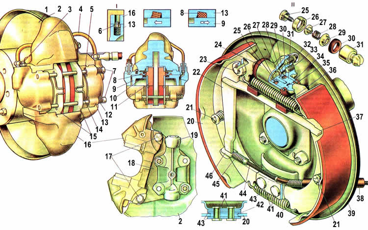
1. Burimet e jastëkëve të fiksimit të kunjave; 2. Pin kotele; 3. Pranvera e fiksimit të pads; 4. Jastekë frenash; 5. Kalibër i frenave; 6. Disku i frenave; 7. Mbulesa mbrojtëse; 8. Gishti i fiksimit të jastëkëve të frenave; 9. Thithë për gjakderdhjen e frenimit; 10. Tub lidhës i cilindrave; 11. Piston; 12. Cilindër rrota; 13. Unaza O e pistonit; 14. Jastëk fërkimi; 15. Kapaku mbrojtës i pistonit; 16. Bllokimi i cilindrit; 17. Thumba për fiksimin e pllakave mbështetëse dhe udhëzuese të jastëkëve; 18. Pranvera e shtrëngimit më të ulët të pads; 19. Pllakë udhëzuese; 20. Këpucë frenash; 21. Kablloja e frenave të parkimit të pasëm; 22. Pranvera e kabllos së pasme; 23. Fundi i kabllos së pasme; 24. Leva e drejtimit të frenave të parkimit; 25. Shirit hapësinor i jastëkave të frenave; 26. Pads drejtojnë gishtin e levës; 27. Trupi i cilindrit të rrotave; 28. Burimi i ndarësit të pistonit; 29. Lidhja për gjakderdhjen e frenimit të pasmë; 30. Pajisja e tubit të hyrjes lëngu i frenave; 31. Unaza O e pistonit; 32. Piston cilindri; 33. Kapaku mbrojtës i cilindrit të rrotave; 34. Stop blloku; 35. Pranvera e kapjes së sipërme të pads; 36. Rreshtimi i jastëkut të fërkimit; 37. Jastekë brinjë; 38. Pranvera; 39. Boshti: 40. Mëngë pranverore; 41. Rondele fërkimi; 42. Bush aks pajisje automatike; 43. Mbulesa e kabllit; 44. Pranvera udhëzuese; 45. Pllaka mbështetëse e mekanizmit të frenimit; 46. Pllaka mbështetëse e pads; 47. I. Frena e rrotave të përparme; 48. II.Mekanizmi i frenimit të rrotës së pasme.
Sistemi i frenave VAZ 2107
Sistemi i frenave të makinës, sipas qëllimit dhe funksioneve të tij, është i ndarë në punë, rezervë dhe parkim. Sistemi i frenimit të shërbimit siguron rregullimin e shpejtësisë së automjetit dhe ndalimin e tij me efikasitetin e kërkuar, ndalimin emergjent të automjetit me efikasitetin e nevojshëm në rast të prishjes së frenave të punës. sistemi i frenave, dhe parkimi që shërben për tu mbajtur makinë në këmbë... Mund të përdoret gjithashtu si urgjencë në rast të dështimit të sistemeve të punës ose të frenave rezervë. Sistemi i frenave të shërbimit ka një makinë hidraulike të veçantë me dy qark për frenat e rrotave të përparme dhe të pasme, gjë që rrit ndjeshëm sigurinë e automjetit. Nëse njëri prej qarqeve dështon, tjetri përdoret si sistem frenimi rezervë, domethënë është pjesë e sistemit të frenave të shërbimit. Aktivizuesi i frenave Aktivizuesi hidraulik përfshin një pedale frenash 50, përforcues vakumi 51, cilindri kryesor 2 i vozitjes hidraulike të frenave, rezervuari 7, rregullatori i presionit të frenave të pasmë 19, cilindrat e rrotave (të punës) të mekanizmave të frenave, tubacioneve dhe tubave. Pedali i frenave 15 është pezulluar nga kllapa 4 së bashku me pedalin e tufës me anë të boshtit 8. Tubat plastikë të ndarë 9 janë instaluar në shpërndarësin e pedalit, përmes të cilit kalon lidhësja e brendshme metalike 5. Pedali i frenave rrotullohet në lidhje me këtë shkurre Pedali lidhet në mënyrë boshtore me shtytësin e përforcuesit të vakumit dhe kthehet në pozicionin e tij origjinal nga forca e pranverës tërheqëse.
Në këtë pozicion, ndalesa e pedalit qëndron kundër tamponit të çelësit të dritës së frenave 49. Përforcuesi i vakumit zvogëlon forcën e aplikuar në pedalin e frenave kur frenoni. Shtë e fiksuar në pllakën e kllapës së tufës dhe frenave në katër kunja me arra. Një copë litari izoluese prej gome është instaluar midis përforcuesit të vakumit dhe pllakës së kllapës. Një brez i jashtëm i një diafragme gome 63 është kapur midis strehimit 77 dhe kapakut 64 të strehimit të amplifikatorit vakum, i cili ndan amplifikatorin në një vakum dhe një zgavër atmosferike. Zgavra e vakumit përmes një zorre 6 me një majë dhe një valvul 58 është e lidhur me tubin e marrjes së motorit. Për të vulosur lidhjen, maja 6 lidhet me një përforcues vakumi përmes një fllanxhë gome. Brenda amplifikatorit të vakumit ekziston një trup plastik i valvulave 65, krahu i të cilit në dalje nga trupi i amplifikatorit vakum është vulosur me një vulë 72. isshtë instaluar në sediljen e trupit të amplifikatorit dhe shtypet kundër fllanxhës së sediljes nga një unazë ndarëse, e cila është e kyçur me një unazë mbajtëse.
Për të mbrojtur krahun e lëvizshëm të trupit të valvulës nga ndotja, një mbulesë mbrojtëse e valëzuar 74 vendoset në pjesën me fllanxhë të trupit të amplifikatorit dhe në krahun e trupit të valvulës. Një pllakë shtytëse 70 hyn në brazdën e pistonit 71, tjetra fundi i të cilit shtrihet në shpatullën e diafragmës 63, e cila e pengon atë të bjerë jashtë. Pllaka 70 fikson në kutinë 65 montimin e pistonit me shtytësin 76 dhe valvulën 73. Tamponi 66 qëndron kundër shufrës së pistonit 61 të cilindrit kryesor. Në dalje nga trupi i amplifikatorit vakum, rrjedha është e ngjeshur nga një vulë 60. e cila shtypet nga kapësja 59 në vendin e trupit të amplifikatorit. Një bulon 78 është i dehur në vrimën fundore të shufrës, e cila rregullon daljen e shufrës nga trupi i amplifikatorit (1.05-1.25 mm). Koka e topit të shtytësit 76 është e shtrënguar në sediljen e pistonit. Valvula e gomës 73 është mbledhur në një shtytës.
Koka e valvulës së lëvizshme, e përforcuar me një rondele metalike, shtypet nga një sustë përmes kupës mbështetëse në skajin e pasëm të pistonit (kur lirohet plotësisht). Trupi 65 ka një vend për kokën e valvulës së lëvizshme. Fllanxha e palëvizshme 73 është e prirur përmes kupës së sediljes kundër murit të brendshëm të shiritit të trupit të valvulës, duke krijuar një vulë të sigurt. Për të pastruar ajrin atmosferik, një filtër ajri prej gome me shkumë 75 është instaluar në krahun e trupit të valvulës. Trupi i valvulës 65 shtypet vazhdimisht nga pranvera 62 drejt kapakut 64. Trupi 77 dhe mbulesa e amplifikatorit janë të lidhura mes vete futja e zgjatimeve të kapakut në gropat e trupit dhe kthimi i mëtejshëm i kapakut derisa skajet e tij të plagosen nën zgjatimet e trupit. Lidhësi i kapakut dhe trupi i amplifikatorit është i mbyllur me një jakë gome diafragme 63, të vendosur në mes tyre. Në strehimin e amplifikatorit, një majë plastike 6 e zorrës është ngjitur përmes një fllanxhë gome, në të cilën është montuar një valvul vakumi 58 për të parandaluar përzierje e djegshme në zgavrën e vakumit të amplifikatorit. Cilindri kryesor 2 frena hidraulikë janë montuar në dy kunja në përforcuesin e vakumit. Në pjesën e sipërme të trupit të tij, ka tre vrima të filetuara për pajisjet e tubave që derdhin lëngun në qarqet lëvizëse të frenave të përparmë dhe të pasmë, dhe dy baza në të cilat pajisjet janë të lidhura me rondele bllokimi, të lidhura me gypat në rezervuarin hidraulik të frenave. Vrima e brendshme cilindrike e cilindrit është e përpunuar me saktësi të madhe dhe përfundim të lartë të sipërfaqes.
Nga njëra anë, zgavra e cilindrit mbyllet me një prizë të filetuar 86. Dy pistona janë instaluar në cilindër në seri, njëra prej të cilave aktivizon frenat e pasme, tjetra - ato të përparme. Burimet kthyese 80 janë instaluar midis prizës dhe pistonit 82, si dhe midis pistoneve 82 dhe 79, nën veprimin e të cilave ata kthehen në pozicionin e tyre origjinal kur lëshohen. Në këtë rast, goditja e pistoneve në cilindër është e kufizuar nga vida 83, krahët e të cilave shkojnë në brazdat gjatësore të pistoneve. Pistoni 82 i makinës së frenave të pasme është vulosur në cilindër me dy unaza 84. Unaza e përparme shtypet në sipërfaqen fundore të brazdës me një sustë 85. Fundi tjetër i pranverës përputhet me pllakën 52. Unaza e pasme shtypet në fundin e pistonit nga pranvera 80 përmes rondele 81 Pistoni i aktivizuesit të frenave të përparmë 79 ka një vulë të ngjashme, vetëm unaza e pasme ndodhet në brazdën e pistonit dhe ka një formë tjetër. Unazat e hapësirës 56 vendosen lirshëm në të dy pistonët. Në pozicionin fillestar të pistonit, unaza ndarëse, e mbështetur në vidën e kyçjes, heq unazën O nga fundi i zakonit. Në këtë rast, përmes hendekut të formuar, zgavra e punës e cilindrit komunikon me rezervuarin e vozitjes hidraulike të frenave. Brazda e unazës së vulosjes së përparme komunikon me zgavrën e punës të cilindrit përmes vrimës radiale dhe kanalit boshtor në pistoni. Prandaj, kur presioni i lëngut rritet në zgavrën e punës, unaza O shtypet më fort kundër gropës së cilindrit.
Rregullimi vijues i pistoneve në cilindër siguron lëvizje të veçantë për frenat e përparme dhe të pasme. Rezervuari i cilindrit hidraulik është me dy seksione, i bërë nga plastika e tejdukshme, e cila siguron kontroll vizual të nivelit të lëngut. Në pjesën e poshtme të trupit të rezervuarit ka dy këshilla për lidhjen e tubave. Një mbulesë 12 është e dehur në qafën mbushëse të rezervuarit, e cila shtyp presionin 10 të pajisjes terminale dhe reflektorin 14 në fund të qafës. Një pajisje për monitorimin e nivelit të lëngut në rezervuar është montuar në strehimin 10. Ai përbëhet nga një notë 15, në shufrën e së cilës ndodhet një kontakt i lëvizshëm 9, dhe një kontakt fiks 8, i fiksuar në një kuti plastike 10. Kur niveli i lëngut bie, nota bie, kontaktet mbyllin qarkun llambë kontrolli dhe ndizet. Një shtytës 11 është instaluar në vrimën qendrore të strehimit të pajisjes terminale, kur shtypet, performanca e qarkut të llambës së kontrollit kontrollohet kur niveli i plotë të lëngshme në rezervuar.
Rregullatori i presionit 19 përfshihet në makinën e frenave të pasme për të parandaluar një rritje të presionit në këtë qark kur ngarkesa në boshtin e pasëm të rrotave zvogëlohet. Përndryshe, rrotat e pasme mund të bllokohen dhe rrëshqasin. Rregullatori i presionit është ngjitur me dy bulona me rondele pranverore në kllapën e trupit, dhe një vrimë në kllapa është ovale, e cila ju lejon të rregulloni pozicionin e rregullatorit të presionit. Rregullatori i presionit aktivizohet nga një levë rrotullimi 20, e cila është e bashkangjitur në trup nga një kapëse 32 përmes një mëngë mbështetëse gome 33. Krahu i gjatë i levës së drejtuesit të rregullatorit të presionit 31 është i lidhur në mënyrë boshtore përmes shiritit 13 me rreze të boshtit të pasmë , dhe krahu i shkurtër kalon nëpër vrimën e boshtit 29 dhe futet në prerjen në fund të pistonit 28 të rregullatorit të presionit. Ky shpatull transferon lëvizjen lëkundëse të rrezes së boshtit të pasmë në pistoni. Pajisjet e dy tubacioneve janë të dehur në trupin e rregullatorit të presionit: ai i poshtëmi për furnizimin e lëngut nga cilindri kryesor, i sipërmi për furnizimin e lëngut në cilindrat e rrotave të frenave të pasmë. Pistoni 28 i rregullatorit të presionit në daljen e kutisë është vulosur nga një unazë 27 e vendosur në kapëse metalike... Ky unazë shtypet kundër pjesës së poshtme të kapakut deri në pranverën 26. Fundi i sipërm i sustës ngjitet kundër pllakës lundruese 24 dhe përmes saj kundër shpatullave të pistonit. Burimi tenton të ngjesh pistonin derisa të ndalet në prizën 21. e cila është e dehur në trupin e rregullatorit të presionit. Një copë litari nënshkrimi është instaluar nën prizë. Tema 22 është e pajisur lirshëm mbi kokën e pistonit. Kufizon lëvizjen lart të vulës 23 drejt kokës së pistonit. Zorrë shtypje e lartë me tre shtresa Pjesa e brendshme 69 dhe pjesa e jashtme 67 e zorrës janë prej gome, me një mbështjellje fije 68 të vendosur midis tyre.Parje dhe dëmtime të tjera në zorrën e jashtme nuk lejohen gjatë funksionimit të automjetit.
Diagrami i sistemit të frenave VAZ 2107
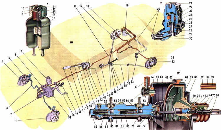
1. Disku i frenave; 2. Cilindri kryesor i vozitjes hidraulike të frenave; 3. Tubacionet e qarkut të frenimit të përparmë; 4. Mbulesa mbrojtëse frena e përparme; 5. Kalibër i frenave të përparmë; 6. Linja vakumi me majë; 7. Rezervuari i cilindrit kryesor; 8. Kontakt fiks; 9. Kontakti në lëvizje; 10. Strehimi i terminalit; 11. Shtytës për kontrollimin e funksionueshmërisë së pajisjes së kontrollit të nivelit të lëngshëm: 12. Kapaku i rezervuarit; 13. Rasti pajisje kontakti: 14. Reflektues; 15. Noton; 16. Tubacioni i qarkut të pasmë të frenimit; 17. Fllanxha e skajit të pasmë të mbështjellësit të kabllit; 18. Cilindri me rrota i frenës së pasme; 19. Rregullatori i presionit të frenave të pasme; 20. Leva e drejtimit të rregullatorit të presionit. 21. Priza e trupit të rregullatorit të presionit: 22. Bush. 23. Vula e kokës së pistonit; 24. Pjatë pranverore. 25 Strehimi i rregullatorit të presionit; 26. Pranvera; 27. Unaza e vulës së pistonit; 28. Pistoni i rregullatorit të presionit; 29. Boshti i levës së drejtimit të rregullatorit të presionit 30 .; 30. Pllaka mbështetëse e levës së drejtimit të rregullatorit të presionit; 31. Këpucë e frenave të pasme: 32. Levë vozitje manuale pads; 33. Rafti i levës së drejtimit të rregullatorit të presionit; 34. Fundi i përparmë i mbështjellësit të kabllit; 35. Kabllo e pasme, 36. Arrë e kyçjes; 37. Arrë rregulluese; 38. Tufë; 39. Udhëzuesi i kabllove të pasme; 40. Rul udhëzues; 41. Kablloja e përparme: 42. Leva e kthimit të frenave të parkimit; 43. Kllapa e levës së frenave të parkimit; 44. Shul levë; 45. Ndalimi i ndërprerësit të llambës paralajmëruese të frenave të parkimit: 46. Tërheqja e shulit të levës; 47. Leva e parkimit të frenave të parkimit: 48. Butoni i levës: 49. Çelësi i dritës së frenave; 50. Pedali i frenave; 51. Përforcues vakum; 52. Kupa mbështetëse e pranverës me unazë O: 53. Thithi: 54. Lavatrice me kyç: 55. Lavatrice: 56. Mëngë me avull: 57. Trupi i valvulave me vakum; 58. Valvula vakumi; 59. Mbajtës i vulës së shufrës; 60. Vula e kërcellit, 61. Rrjedha; 62. Pranvera e kthimit të trupit të valvulës: 63. Diafragma: 64. Mbulesa e trupit të valvulës së përforcuesit të vakumit; 65. Trupi i valvulës së amplifikatorit të vakumit; 66. Tampon i rrjedhës; 67. Mbulesa e jashtme prej gome e zorrës së frenave; 68. Mbulesa e fijes së zorrës së frenave: 69. Mbulesa e brendshme prej gome e zorrës së frenave: 70. Pllaka e shtytjes së pistonit: 71. Pistoni i valvulës: 72. Vula për kapakun e strehimit të përforcuesit vakum; 73. Valvula përforcuese e vakumit; 74. Kapaku mbrojtës i trupit të valvulës; 75 Filter ajri; 76. Valvula shtytëse e përforcuesit të vakumit; 77. Trupi i valvulës vakum: 78. Rrufeja rregulluese stok; 79. Pistoni i frenimit të përparmë: 80. Pranvera e kthimit të pistonit; 81. Rondele shtytëse; 82. Pistoni i frenimit të pasmë: 83. Vidë kufizuese e pistonit; 84. Unaza O; 85. Pranvera e unazës O: 86. Priza e zorrës së cilindrit kryesor; 87. I. Rezervuari i cilindrit kryesor; 88. I. Rregullatori i presionit; 89. III. Qarku i drejtimit të frenave, 90. IV. Cilindri kryesor dhe përforcuesi i vakumit.
Puna e sistemit të frenave VAZ 2107
Kur sistemi lëshohet dhe pedali i frenave, nën veprimin e pranverës 32, tërhiqet kundër ndalesës kundër çelësit të llambës së ndalimit 34, shtytësi 31 me pistonin 26 të përforcuesit të vakumit tërhiqet së bashku me pedalin. Trupi i valvulës 20 dhe rrjedha 17 janë të shtypura nga pranvera 19 në pozicionin ekstrem të pasmë. Në këtë pozicion, formohet një hendek midis kokës së valvulës 27 dhe sediljes së valvulës, pasi pistoni e shtyn valvulën nga vendi. Zgavra e vakumit A përmes kanalit B, hendeku midis sediljes dhe valvulës dhe pastaj përmes kanalit C komunikon me zgavrën atmosferike D. Prandaj, kur motori po funksionon, vakumi nga tubi i marrjes përmes valvulës 18 transmetohet në zgavrën A dhe përmes kanaleve dhe hapjeve në zgavrën D. Pistonët 11 dhe 15 të cilindrit kryesor, nën veprimin e burimeve të kthimit, janë të shtypur në pjesën e pasme pozicion ekstrem kundër vidhave të ndalimit 8, shtypni unazat e vulosjes 9 nga fundi i zakonit të pistonit dhe përmes boshllëqeve të formuara zgavrat e punës të cilindrit komunikojnë me rezervuarin e cilindrit hidraulik dhe tubacionet me presion të lartë.
Kështu, nuk ka presion në makinën e frenave. Prandaj, pistonët 4, nën veprimin e deformimit elastik të unazave të vulosjes 3, tërhiqen brenda cilindrave dhe nuk ushtrojnë presion mbi pllakat e frenave të frenave të përparmë, të cilat do të jenë në kontakt të lehtë me sipërfaqen e frenave disku Kur makina po lëviz pa frenuar, domethënë kur është brenda makinë hidraulike nuk ka presion, pistoni 36 nën veprimin e sustës 40 dhe levës së rrotullimit 42 ngrihet deri në ndalesë kundër prizës 35. Prandaj, zgavrat e trupit mbi dhe poshtë kokës së pistonit komunikojnë lirshëm. Kjo hap kalimin e lirë të lëngut në cilindrat e rrotave të pasme të frenave. Por meqenëse nuk ka presion në të gjithë makinën, jastëkët e frenave 43 janë të shtrydhur nga daullet. Kur frenoni, kur shoferi shtyp pedalin e frenave, shtytësi 31 lëviz pistonin 26. Pas pistonit, valvula 27 lëviz nën veprimin e sustës 28 derisa të ndalet kundrejt sediljes së trupit të valvulës. Kur vendi është i mbyllur, zgavrat A dhe D ndahen.
Me lëvizjen e mëtejshme të pistonit 26, formohet një hendek midis tij dhe fllanxhës së valvulës 27 përmes së cilës zgavra D komunikon me atmosferën. Jashtë ajrit hyn në zgavrën D përmes filtrit të ajrit 30, përmes hendekut midis shtytësit dhe valvulës dhe pastaj përmes kanalit C. Ajri atmosferik krijon presion në diafragmën 21. Për shkak të ndryshimit të presionit në zgavrat A dhe D, si dhe forcën e duke shtypur pedalin e frenave, trupi i valvulës lëviz së bashku me shufrën 17, e cila nga ana tjetër vepron në pistonin 15 të cilindrit kryesor. Forca në trupin e valvulës varet nga vakumi në kolektorin e marrjes së motorit dhe nga forca në pedalin e frenave. Kur pistoni 15 lëviz, mëngë ndarëse 13 largohet nga vida e kyçjes 8 dhe unaza e vulosjes 9 shtypet nga pranvera 12 në fund të brazdës së pistonit. Kështu, hendeku i zgjerimit mbyllet dhe zgavrat e cilindrit dhe rezervuarit ndahen. Prandaj, me lëvizjen e mëtejshme të pistonit 15 në zgavrën e punës të makinës së frenave të përparme, krijohet presioni i lëngut, i cili transmetohet përmes tubacioneve dhe tubave në cilindrat e rrotave të frenave të përparmë. Ajo gjithashtu vepron në pistonin lundrues 11, i cili, ndërsa lëviz, krijon presion në vozitjen e frenave të pasme. Nën presionin në rritje të lëngut në dhomat e punës, unazat e para të pistoneve zgjerohen dhe fillojnë të ngjiten më fort në sipërfaqen e cilindrit dhe në fund të brazdave, duke përmirësuar vulosjen e pistoneve në cilindër. Nën presionin e lëngut, pistonët e cilindrave me 4 dhe 44 rrota të frenave të përparme dhe të pasme janë zgjatur, duke shtypur jastëkët kundër disk frenash 1 dhe në daulle. Çift rrotullues të frenimit që rezultojnë ngadalësojnë rrotullimin e rrotave të përparme dhe të pasme. Në këtë rast, ngarkesa rishpërndahet përgjatë akseve të makinës: ngarkesa në boshtin e përparmë rritet, në boshtin e pasmë zvogëlohet. Kjo bën që porta e pasme të ngrihet, domethënë, rritet distanca midis rrezes së boshtit të pasmë dhe trupit.
Në këtë rast, krahu i shkurtër i levës 42 ulet, dhe pistoni 36 i rregullatorit të presionit nën presionin e lëngut fillon të ulet, duke ngjeshur pranverën 40. Në momentin e frenimit të plotë, lëvizja maksimale e ngarkesës ndodh me boshti i pasmë në pjesën e përparme dhe ngritjen më të lartë të trupit. Mbërthimi i rrotave me rrugën përkeqësohet, presioni i krahut të rrotullimit 42 në pistonin 36 zvogëlohet. Për shkak të sipërfaqes më të madhe të skajit të kokës së pistonit, forca nga presioni P2 i lëngut e ul pistonin poshtë derisa koka të vijë në kontakt me vulën 38. Rrjedha e mëtejshme e lëngut në cilindrat e rrotave të pjesës së pasme frenat ndalojnë, domethënë çift rrotullimi i frenimit në rrotat e pasme nuk rritet, pavarësisht depresionit të fortë të pedalit të frenave dhe një rritje të mëtejshme të presionit P,. Prandaj rrotat e pasme nuk janë të bllokuara dhe makina nuk rrëshqet. Kur pedali i frenave lëshohet, ai kthehet në pozicionin e tij origjinal nën veprimin e pranverës së kthimit 32, duke tërhequr shtytësin 31 dhe pistonin 26 me të.
Pastaj koka e valvulës largohet nga vendi dhe zgavrat A dhe O komunikohen, d.m.th. presioni në të dy zgavrat është i barabartë, nën veprimin e pranverës 19, trupi i valvulës me rrjedhin kthehet në pozicionin e tij origjinal, duke ndaluar shtypjen në pistonin 15 të cilindrit kryesor. Pistonët 11 dhe 15, nën forcën e burimeve të kthimit, shtrydhen në pozicionin ekstrem dhe qëndrojnë kundër vidhave të kyçjes 8. Mëngë hapësirë unazat e vulosjes 9 hiqen nga fundi i brazdave, dhe përmes hendekut të formuar, zgavrat e punës të cilindrit kryesor komunikojnë me zgavrat e rezervuarit. Pistonët e frenave të përparmë 4 tërhiqen nga pads për shkak të elasticitetit të unazave O 3, dhe pistonët e pasmë të frenave 45 tërhiqen nga burimet e ngjeshjes.
Në rast të dështimit të qarkut të pasmë të frenimit, për shkak të rrjedhjeve të tij, pistoni 11 nën presionin e lëngut lëviz në ndalesë në prizën e cilindrit kryesor, pas së cilës presioni në qarkun e përparmë të frenimit fillon të rritet. Për shkak të lëvizjes së lirë të pistonit I, udhëtimi i lirë i pedalit të frenave rritet dhe aktivizohen vetëm frenat e përparmë. Nëse qarku i përparmë i frenimit dështon, pistoni 15 lëviz përpara derisa të ndalojë në pistonin 11, pas së cilës qarku i frenimit të pasëm fillon të funksionojë. Vrapim i lirë pedali i frenave gjithashtu rritet. Nëse ndonjë qark është dëmtuar, llamba e kontrollit të nivelit të lëngut ndizet, duke sinjalizuar një rënie të nivelit të lëngut në rezervuar.
Skema e sistemit të frenave VAZ 2107

1. Disku i frenave; 2. Jastëku i frenave të përparmë; 3. Unaza O e pistonit; 4. Pistoni i cilindrit të rrotave; 5. Cilindri i rrotave të frenave të përparme; 6 Tubi i frenave qark i frenimit të përparmë; 7. Gishti i fiksimit të jastëkave të frenave: 8. Vida kufizuese e goditjes së pistonit; 9. Unaza O; 10. filxhan rezistent; 11. pistoni i frenimit të pasëm; 12. Pranvera e unazës vulosëse; 13. Bush; 14. Trupi i cilindrit kryesor: 15. Pistoni i përparmë i frenimit: 16. Vula; 17. Stoku; 18. Valvula vakumi; 19. Pranvera e kthimit të trupit të valvulës; 20. Trupi i valvulës: 21. Diafragma: 22. Trupi i valvulës vakum; 23. Mbulesa e trupit të amplifikatorit vakum; 24. Tampon i rrjedhës; 25. Pllaka shtytëse e pistonit; 26. Piston; 27. Valvula e përforcuesit të vakumit; 28. Pranvera e valvulave; 29. pranvera e kthimit të valvulave; 30. Filtri i ajrit; 31. Shtytës valvulash; 32. Pranvera e lëshimit të pedalit: 33. Ndaloni majën e kalimit të dritës; 34. Çelësi i dritës së frenave; 35. Priza e trupit të rregullatorit të presionit; 36. Pistoni i rregullatorit të presionit; 37. Llastik trupi; 38. Vula e kokës së pistonit: 39. Pllakë pranvere; 40. Pranvera e pistonit; 41. Unaza O e pistonit të rregullatorit të presionit; 42. Leva e drejtimit të rregullatorit të presionit; 43. Këpucë e frenave të pasme: 44. Padë kthejnë jastëkë; 45. Pistoni i cilindrit të rrotave të frenave të pasme; 46. Burimi i ndarësit të pistonit; 47. Vula për pistonët e cilindrave të rrotave; 48. Pedale frenash; 49. A. Zgavra me vakum; 50. B. Kanali që lidh zgavrën e vakumit me zgavrën e brendshme të valvulës; 51. C. Kanali që lidh zgavrën e brendshme të valvulës me zgavrën atmosferike; 52. D. Kaviteti atmosferik; 53. K. Çorape. lidhja e përforcuesit të vakumit me tubin e marrjes së motorit; 54. I. Pedali nuk është i shtypur; 55. I. Frenimi; 56. III.Shtypja e pedalit pezullohet; 57. IV. Tërheqja.
Burimi i informacionit Faqja: http: //1avtorul.ru/vaz/vaz-2107.html
Dua të ndaj informacione për punën time të kryer.
Përgatitja e një makine për të tërhequr donuts në asfalt dhe për dredhje në rrugë.
Në të njëjtën kohë, një minimum financash të shpenzuara.
- Para së gjithash bleva një bosht të përdorur me kuti ingranazhi 2101
Cmimi 1500 re
- Pastaj e çmontova, e lava, vula vaji dhe vaj për zëvendësim, natyrisht, pjesa tjetër ishte në gjendje të mirë.
Çmimi 650 r
- Unë ngjita një kuti ingranazhesh 4.3 e cila ishte në urë, sepse kuti ingranazhi 2102 nuk e gjeta shpejt.
Çmimi 0 ri- 2-3 elektroda dhe punë manuale
- Blerë 2 shtytje të mesme (500 re), stabilizues (1400 re), vezë 2110 ss20 (500 re)
Çmimi 2400 rub
- Fillova të gatuaj lidhëse dhe të forcoj atë aktuale. u përdor metali me trashësi 3mm dhe 8mm
Çmimi 0 ri- gjithçka doli të ishte në dorë në garazh
- Bleva një montim të shufrës për trupin (250 re), dhe bulona, arra, rondele.
Çmimi 500 r
- Bleva një çantë riparimi për shufrat
Çmimi 500 r
- Bleva përbërës për prodhimin e shufrës Panhard
Çmimi 600 r
Gjithsej 6150 re
Kostot me vlerë 6150 rubla, nuk përfshijnë burime dhe armatura. Mund të pakësoni pak kostot, nëse nuk blini një urë të re të përdorur, shiriti do të ulet në 4650 re.
Epo, tani për gjënë kryesore, si bëhet gjithçka:
1. Pasi bleva urën, hoqa kutinë e shpejtësisë dhe lava urën dhe kutinë e marsheve me benzinë.
2. Unë ngjita kutinë e shpejtësisë, pas së cilës duhet të pastrohet nga gjurmët e saldimit (spërkatjet) dhe të shpëlahet përsëri.
3. Kur montova urën, ndryshova vulat e vajit përsëri, ato të vjetra ishin të papërdorshme.
4. Për fabrikim fiksim shtesë për shufra, modele të bëra nga kartoni. Pastaj e preva prej metali me një trashësi prej 3mm. Për të bashkuar pjesët e punës, e mblodha atë sikur të ishte ngjitur tashmë dhe është në makinë, d.m.th. vendosni dy shufra nëpër fiksuesit e përgatitur dhe i shtrëngoni me një rrufe, i kapni me saldim, pastaj çmontoni dhe përvëloni gjithçka.
5. Montimi i armos duhej të ribëhej, kështu që metali 8mm u mor për përforcim, pas së cilës një vrimë u bë e përshtatshme për atë të fabrikës dhe u ngjit. Për të fiksuar armaturat, u përdor një rrufe në qiell nga gjatësia e shtytjes dhe u ngjit nga ana e goditjes.
6. Pas të gjitha këtyre veprimeve, ura u instalua në makinë.
7. Pastaj montimi i tërheqjes u mor në trup dhe u sharrua në gjysmë, në të majtë dhe ana e djathte... Instaluar shufra të dyfishta, u përpoq në një kllapa gjysmë në trup, përshkroi një vend për shpimin e vrimave. Pas kësaj, unë shpova trupin dhe ngjita bulonat në trup nga ndarja e pasagjerëve në të njëjtën mënyrë si montimi i fabrikës.
8. Vezët e furnizuara me komplet nuk janë të përshtatshme për instalimin e stabilizatorit. për shkak të shufrave shtesë, lartësia e stabilizatorit e zhvendosur në brendësi të makinës përkon me lartësinë e shufrave dhe vezët prekin shufrat. Për të dalë nga kjo situatë, bleva vezë 2110 të përforcuara ss20 dhe shpova një mëngë deri në 12 mm në diametër, sepse të afërmit shkojnë 10 mm. Pas kësaj, stabilizuesi ngrihet lehtësisht pothuajse mbi urë dhe nuk prek asgjë, dhe jo sesi e instaloj nën urë, ndërsa ndryshoj hapësirën e makinës.
9. Për të krijuar një shufër panhard, u desh tërheqje vendase, duke rrotulluar këshilla drejtuese VAZ 2108 2 copë, rrotulluese maja drejtuese VAZ 2110 1 copë, arrë bllokimi me fije të majta dhe të djathta 1 pc. E gjithë gjë matet me një masë kasetë, prerë dhe ngjitur.
Gjendja e pezullimit në rimorkio është e lehtë të vlerësohet me sy. Kjo zakonisht bëhet në një gropë ose ashensor. Tufat elastike të shufrave dhe amortizatorëve i nënshtrohen zëvendësimit nëse:
gome e plasaritur;
mëngë e brendshme dhe vrima e syrit nuk janë të rreshtuar;
gjurmë të dukshme të kthimit të mëngës së brendshme në gome (thërrime, boshllëqe).
Pikat e naftës në strehimin e amortizatorëve janë një sinjal për ta zëvendësuar atë. Edhe shoferët fillestarë mund të përballojnë riparime, dhe pajisjet e thjeshta të përdorura janë të lehta për t'u bërë vetë.
Mbërthimet e rrotave janë vendosur nën rrotat e përparme. Ne pastrojmë me një furçë çeliku dhe njomet skajet e filetuara të shufrave dhe amortizatorëve me një lëng depërtues (për shembull, vajguri). Ne i zëvendësojmë pjesët një nga një, duke mos lejuar që ura të "zgjidhet" plotësisht nga trupi.
Për të hequr shiritin gjatësor, montimi i poshtëm i amortizatorit është shkëputur.
Sekuenca e operacioneve 3-5 është arbitrare.
Moreshtë më fitimprurëse të blini tufa elastike për varen e shufrave dhe amortizatorëve si grup, por ju duhet të ekzaminoni me kujdes grupin edhe në dyqan.
Tufat e shufrave gjatësore të sipërme janë pak më të vogla, por teknika dhe pajisjet për zëvendësimin e tyre janë të njëjta.
Në vend të kësaj, mund të përdorni një top me diametër 20 mm nga kushineta.
Varet e amortizatorëve përbëhen nga dy elemente gome të lidhura me një mëngë çeliku. Tufat e gomës shtypen nga anët me rondele sferike.
Për të hequr "gjysmat" e konsumuara të menteshës, mjafton t'i hiqni ato me një kaçavidë.
Kur instaloni amortizuesin në makinë, shtrëngoni arrën e bulonit të fiksimit derisa skajet të ndalojnë me mëngën e çelikut të menteshës në rondele sferike (forca në arrë rritet ndjeshëm). Kjo arrin para -ngarkimin e nevojshëm në tufat e gomës.
Në praktikën e riparimit amator, ekzistojnë dy metoda të zakonshme që lehtësojnë shtypjen, por ... janë njësoj të pasakta:
- lubrifikoni sipërfaqet e pjesëve me ndonjë vaj;
- bëni një "vrapim" duke rritur diametrin përgjatë skajit të vrimës në mëngën e gomës, ose mprehni çelikun në një kon.
Të dyja metodat janë të papranueshme, pasi ato ndryshojnë parimin e funksionimit të menteshës prej gome-metali, duke zvogëluar jetën e tij të shërbimit. Metoda e parë çon në fryrjen e gomës dhe kthimin e mëngës së çelikut element elastik... E dyta zvogëlon zonën e kontaktit të mëngës së çelikut me nofullat e kllapës - kjo çon në shtypje të shpejtë dhe rrotullim të mëngës.
Gjendja e kërkuar punë e qëndrueshme varet - shtrëngimi përfundimtar i fiksuesve në ngarkesën nominale të automjetit.
Me kalimin e kohës, ngurtësia e burimeve të pezullimit të makinës zvogëlohet aq shumë sa trupi "i varur" nuk lejon gjithmonë që të metat e rrugës nën të. Ngurtësia e burimeve të gjetura në treg sot rritet me porosia e radhës kodimi i ngjyrave: jeshile, e verdhë, kafe (për vagonët e stacioneve). Nëse është e nevojshme, zëvendësoni burimet - një nga një. Së pari, ne lirojmë fiksimet e të gjitha varen prej gome-metali të pezullimit të pasmë (shufra, amortizues) në mënyrë që tufat të mos rrotullohen.
Mbani në mend: në gjendjen e pa shkarkuar, gjatësia e pranverës duhet të jetë 434 mm, dhe në treg mund t'ju ofrohen "produkte" me të njëjtat tetë kthesa, por gjatësia është një herë e gjysmë më e gjatë. Këto janë zakonisht produkte "të majta" që kryesisht do ta bëjnë pezullimin e pasmë jashtëzakonisht të ngurtë. Për më tepër, burime të tilla mund të hiqen ose instalohen në vend vetëm duke u përshtatur posaçërisht, për shembull, duke shtrënguar kthesat e tyre me lidhëse, siç tregohet në fotografi. Për burime standarde nuk është aspak e nevojshme.
Shkëputeni montuesin e poshtëm të amortizatorit dhe ngrini trupin mjaftueshëm për të hequr sustën, por jo për të thyer zorrën e frenave.
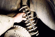 |
|
Ne nxjerrim unazën e pranverës dhe të mbështetjes. | Zëvendësoni unazën e vjetër të deformuar (majtas) me një të re. Përndryshe, spiralja e pranverës që prek trupin do të fshijë vrimën në bagazhin. |
|
|
Nëse në pranverën e re njëri nga skajet drejtohet, atëherë e orientojmë drejt trarit të urës (poshtë). | Ne e instalojmë pranverën në mënyrë që tamponi i trupit të përshtatet në unazën mbështetëse dhe kthesat e sipërme, dhe kthesa e poshtme në brazdën e kupës së boshtit. |
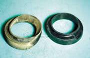
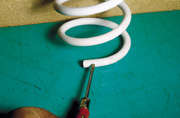
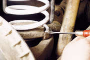
Ne e ulim trupin, rregullojmë amortizuesin (mbahemi nën ngarkesë); duke shtyrë në krah, hiqni kapëset.