timoni MTZ-80, i cili gjithashtu përfshin kolonën e drejtimit, është krijuar për të kthyer rotacionin e timonit në lëvizjen e kthesës së rrotave në një aeroplan vertikal.
Kolona drejtuese montuar në panelin e përparmë të kabinës së traktorit pa lëvizje, e cila lejon që ajo të kthehet lart me timon gjatë uljes dhe zbarkimit të drejtuesit. Boshti drejtues, nga ana tjetër, është i lidhur pa lëvizje me segmentin tjetër të boshtit nga një bashkësi universale, dhe pastaj, përmes një mbështetje të ndërmjetme dhe një tjetër bashke universale, me një drejtues të energjisë hidraulike - GUR. Boshti shtytës i timonit përmes mëngës rrotulluese transmeton rotacionin në krimbin e fiksuar në kushineta në mëngën e çuditshme. Krimbi transmeton rotacionin në sektorin e rrotave të krimbit, të montuar në vijën e një boshti rrotullues të vendosur vertikalisht. Boshti rrotullohet bipodi i montuar në skajin e tij të poshtëm të pjerrët, dhe bipodi lëviz të gjithë trapezoidin drejtues përmes levave.
Sipas kësaj skeme, procesi i drejtimit të traktorit ndodh kur timon nuk transmetohet shumë përpjekje nga rrotat. Në një rrugë të mirë, rrotat nuk plotësojnë rezistencë të shtuar kur kthehen dhe për procesin e taksimit, përpjekja muskulore e shoferit të traktorit MTZ - 80 është e mjaftueshme.
Kur lëvizni në tokë viskoze ose jashtë rrugës, rrotat rrisin rezistencën ndaj rrotullimit të drejtimit. Në një situatë të tillë, përforcuesi hidraulik përfshihet automatikisht në operacion.
Përmirësuesi hidraulik përbëhet nga njësitë e mëposhtme:
- strehimi;
- pompë hidraulike;
- cilindri hidraulik;
- sensori i kyçjes diferenciale.
Me një rritje të ngarkesës në timon, mekanizmi i drejtimit funksionon si më poshtë:
Pas transferimit moment rrotullues nga boshti i helikës për shkak të ngarkesës së shtuar, krimbi nuk mund ta kthejë sektorin e veshjeve të krimbit përmes lidhjes spline. Dhe që nga boshti i helikës timoni e informon atë për lëvizjen rrotulluese, krimbi, duke u angazhuar me sektorin, fillon të vidhoset në të, duke bërë një lëvizje drejtvizore së bashku me kushinetat. Në fund të krimbit, është fiksuar një valvul rrëshqitëse, e cila, duke lëvizur së bashku me krimbin, hap kanalin, dhe vaji nga pompa nën presion hyn në zgavrën pa shirit (kur kthehet në të majtë) të cilindrit hidraulik. Pistoni i cilindrit hidraulik, duke lëvizur nën ndikimin e presionit të vajit, shtyn hekurudhën e fiksuar në shufrën e saj. Raft është në angazhim të vazhdueshëm me sektorin e ingranazheve, i cili është integral me sektorin e rrotës së krimbit dhe i montuar në një bosht rrotullues. Boshti rrotullues rrotullohet dhe transmeton momentin e rrotullimit në bipod. Kështu, rrotullimi i rrotave është për shkak të përpjekjeve të hidraulikës.
Spool, i cili është zhvendosur nga krimbi, mbërthehet në banesën e shpërndarësit nga burimet e kthimit me shumë përpjekje dhe mund të lëvizë vetëm nëse krimbi e kapërcen këtë forcë. Kur traktori MTZ-80 drejton rrugë e mirë dhe rrotat nuk i rezistojnë rrotullimit të bipodit dhe boshtit rrotullues, krimbit, timon, nuk e plotëson përpjekjen kur kthen sektorin e veshjeve të krimbave, të mjaftueshme për të lëvizur rrotullimin. Prandaj, rrotullimi mbetet në pozicionin e tij neutral, dhe rrotat kontrollohen pa ndërhyrjen e përforcuesit hidraulik.
Kështu, amplifikatori ndizet automatikisht, në varësi të kushteve të rrugës.
Rrota kur ktheni traktorin MTZ - 80 rrokulliset në rrathë me rreze të ndryshme dhe për këtë arsye shpejtësia këndore të ndryshme të tyre. Për të mundësuar rotacionin falas të rrotave, diferencial boshti i pasmë duhet të zhbllokohet.
Për ta bërë këtë, një sensor është montuar në strehën e përforcuesit hidraulik që kontrollon bllokimin diferencial të z / urës. Një shpërndarës presioni hidraulik me një valvul shpërndarësi është i vendosur në strehën e sensorit. Fundi i brendshëm i bobinës është i pajisur me një top, i cili, kur cilindri hidraulik është në pozitë neutrale, hyn në vrimën e vargut të hekurudhës të fiksuar në fund të shufrës së pistonit. Gjatë kthesës, pavarësisht nëse përforcuesi hidraulik po punon apo jo, sektori i ingranazheve, i montuar në boshtin rrotullues, tërheq raftin e lidhur me shufrën.
Kur hekurudha lëviz në një drejtim ose në një tjetër, pështjella lëviz nga gropa e V - dhe hap kanalin për furnizimin e naftës përmes tubacionit në diferencialin e boshtit të pasëm për ta zhbllokuar atë.
Mirëmbajtja e drejtimit nuk është e vështirë: kontrolloni vazhdimisht nivelin e vajit në kavilje veshje drejtuese, kontrolloni fiksimin e lidhjeve të bulonave, arrave të fiksimit të bipodit dhe arrës së kundërt të vidhave rregulluese. Kur rritni lojën në timon, rekomandohet një kontroll i përbashkët. driveshafts, leva, shufra, gishta topash. Kryeni rregullimin e boshllëqeve të ingranazheve të krimbit dhe raftit.
Nëse rregullime të tilla nuk japin rezultate të duhura, atëherë është e nevojshme të rregulloni drejtuesin.
Së pari ju duhet të hiqni tërë asamblenë e mekanizmit. Për ta bërë këtë, kullojeni vajin, shkëputni bifodin, boshtin e helikës, të gjitha tubacionet hidraulike të tubave dhe vidhave të strehimit.
Lani plotësisht rastin dhe vendoseni në tavolinën e punës. Përgatitni një mjet për çmontimin - rrotullues, çelësa të veçantë. Hiqni kapakun e boshtit rrotullues, strehimin e cilindrit hidraulik, sensorin e kontrollit diferencial. Hiqni boshtin e strumbullarit. Hiqni strehën e krimbit me valvulën e sigurisë. Shpëlarje të gjithë komponentët dhe çmontoni ato në pjesë duke përdorur një tërheqës.
Zëvendësoni krimbin, burimet e kthimit, sektorin e dhëmbëzuar të dyfishtë, hekurudhat.
Matni veshin e bobinave, gjendjen e rrotave të boshtit rrotullues, kushinetave. Zëvendësoni nëse është e nevojshme. Çmontoni dhe kontrolloni të gjitha nyjet në shufra drejtimia, në nyje kardanesh. Për të prodhuar riparim riparimi ose thjesht zëvendësoni pjesët e veshura.
Kontrolloni pompën hidraulike në stol për performancën dhe presionin.
Mblidheni në rend të kundërt, duke vëzhguar çift rrotullimet shtrënguese të arrave dhe rregulloni vidhat me një pikëllim çift rrotullues. Për të instaluar sektorin e ingranazheve të dyfishta në një bosht rrotullues, duke pasur etiketa të kombinuara. Gjithashtu, me anë të etiketave, vendosni bipodin. Mëng i çuditshëm rregullon pastrimin në dhëmbëzim krimbi. Rregulloni sensorin e kontrollit diferencial.
Pas montimit, drejtimi i energjisë kontrollohet në vendndodhjen për presion pune, përpjekje për një timon dhe lëvizjen e saj të lirë. Të gjitha specifikimet duhet të plotësojnë kërkesat. dokumentacionin teknik funksionimi i traktorit MTZ-80.
Riparimi drejtues, ky është një moment shumë i rëndësishëm në riparimin e çdo pajisje. Siguria e njerëzve përreth jush, përfshirë edhe veten, do të varet nga sa mirë bëhet riparimi i drejtimit. Riparimi drejtues, është më mirë t'u besohet specialistëve me përvojë të gjerë në këtë çështje. Në Moskë dhe rajonin e Moskës, riparimi i ingranazheve drejtuese pajisjet e traktorit, e angazhuar në organizatën "Tractor Service". Specialistët e Shërbimit Traktor identifikojnë shpejt problemin e drejtimit, e eleminojnë atë brenda një kohe të shkurtër, për këtë, ka gjithçka në bazë të Shërbimit Tractor pajisjet e nevojshme. Besoni riparimin e drejtimit vetëm nga një specialist, në asnjë rast mos e rregulloni vetë nëse nuk keni njohuri të veçanta. Riparime cilësore veshje drejtuese, kjo është kryesisht siguria juaj.
Kolona drejtuese e Zëvendësimit të videos MTZ 80
Drejtimi është krijuar për të siguruar dhe mirëmbajtur lëvizjen drejtvizore, si dhe për të ndryshuar drejtimin e lëvizjes së traktorit duke e kthyer atë rrota të drejtuara. Drejtimi përbëhet nga një trapezoid, mjet drejtues dhe mjet drejtues.
Në traktorët MTZ-80 dhe MTZ-82, drejtimi është i pajisur me një përforcues hidraulik.
Trapezoidi drejtues siguron rrota drejtuese të majtë dhe të djathtë kënde të ndryshmenë të cilën përpara dhe rrotat e pasme rrotullohen në lidhje me qendrën e zakonshme të rrotullimit të vendosur në shtrirjen e boshtit rrotat e pasme. Për shkak të kësaj, rrotat rrokullisen përgjatë qarqeve koncentrike pa rrëshqitje anësore.
Trapezoidi i drejtimit formohet nga dy shufra drejtimi tërthor të lidhur nga një bipod 4 (Fig. 47), dy leva qendrore 6 dhe një rreze e boshtit të përparmë.
Fig. 47. Boshti i përparmë (pamja e sipërme):
1 - fund shufra kravatë; 2 - një arrë me kyç; 3 - gypi drejtues; 4 - bipod; 5 - gisht; 6 - levë rrotulluese.
Kur traktori lëviz në një bipod të drejtë, ai është i vendosur në pozicionin e mesëm (përgjatë boshtit gjatësor të traktorit). Pozicionet ekstreme të bipodit gjatë këndimit janë të kufizuara nga goditja e pistonit të drejtuesit të energjisë. Këndi maksimal i rrotullimit të rrotës së brendshme është 40 °, ndërsa rrota e jashtme rrotullohet 30 °.
Secila shufër drejtimi përbëhet nga një tub lidhës 3 dhe dy këshilla 1, njëra prej të cilave është me një fije të dorës së majtë, tjetra me një fije të dorës së djathtë.
Këshillat janë mprehur në vrimat e filetuara të tubit dhe sigurohen me arra të bllokuara 2. Brenda majës ka një vrimë sferike që përbëhet nga një kunj sferik 2 (shiko fig. 43) dhe dy futje 4 dhe 5 (gome dhe kapron). Në fabrikë, varet është e mbushur me yndyrë të veçantë afatgjatë që nuk kërkon rimbushje në operacion. Varet është e mbrojtur nga lagështia, pluhuri dhe papastërtia nga një mbulesë gome 3 dhe një prizë rregulluese gome 6, e cila kompreson futjet e varen. Skajet e filetuara të kunjave të topave të filetuar futen në vrimat e krahëve të varur dhe dy biodë, të shtrënguar me arra të çara dhe të ndara.
Ingranazh drejtues (Fig. 48) përdoret për të transmetuar rrotullimin nga timoni në drejtuesin dhe drejtuesin e energjisë. Forca transmetohet nga boshtet 3, 5, 10 dhe 13, të ndërlidhura nga nyjet universale 8 dhe 12.
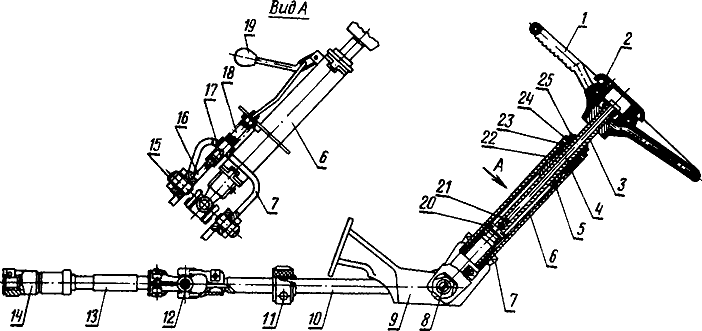
Fig. 48. Makinë drejtuese:
1 - një timon; 2 - një fluturues; 3 - një bosht drejtues; 4 - vidhos; 5 - countershaft; 6 - një tub kolonash drejtuese; 7 - vathë; 8 dhe 12 - nyje kardan; 9 - raft; 10 - boshti mesatar; 11 - mbështetje e ndërmjetme; 13 - boshti i përparmë; 14 - mëngë e praruar; 15 - vidhos; 16 - muri i djathtë i raftit; 17 - një pirg; 18 - pranverë; 19 - trajtuar; 20 - pin; 21 dhe 24 - arrë; 22 - mëngë; 23 - amortizues; 25 - një arrë me kyç.
Pozicioni i timonit mund të ndryshohet në lartësi, përveç kësaj, kolona e drejtimit mund të rrotullohet në aeroplanin gjatësor - anim përpara përgjatë traktorit. Lartësia e timonit është rregulluar për lehtësinë e funksionimit, dhe pjerrësia e kolonës së drejtimit është për hyrje dhe dalje më të lirë nga kabina.
Tubi 6 i kolonës së drejtimit është ngjitur në vathën 7, i cili është i varur në rripin 9 duke përdorur dy vida 15, boshtet e të cilave përkojnë me boshtin e kryqit të varen 8. Kjo lejon që kolona e drejtimit të rrotullohet në lidhje me rripin 9, të bulonuar në murin e përparmë të kabinës. Mbërthimi i ingranazhit drejtues në kabinën e montuar në skeletin e traktorit në amortizuesit zvogëlon transmetimin e dridhjeve në timon.
Në pozicionin e poshtëm, të punës, kolona e drejtimit është e mbajtur nga një shul 17, e cila angazhohet në brazdën e murit të djathtë 16 të raftit 9 dhe shtypet nga pranvera 18. Për ta kthyer kolonën drejtuese, duhet të lëvizni dorezën 19 drejt jush, dhe shulja 17 do të dalë nga brazda. Pas kësaj, kolona mund të kthehet lehtësisht lart, ndërsa shulja rrëshqet në sipërfaqen e murit 16 të raftit 9. Kolona e drejtimit në pozicionin e sipërm, jo \u200b\u200bfunksional, nuk është fikse, por mbahet vetëm nga forca e fërkimit të shulit në sipërfaqen e murit të raftit.
Kolona e drejtimit në pozicionin e poshtëm, të punës, vendoset duke e zhvendosur atë deri sa shulja të futet në brazdë në raft.
Timoni 1 është montuar në vrimat e boshtit të uritur 3, brenda së cilës ka një vidhë 4 të lidhur me një dorezë plastike 2. Vidhosja është e dehur në arrë 21, në të cilën shtypet kunj 20. Pina hyn në brazdën gjatësore countershaft 5 dhe përjashton rrotullimin e arrave. Rrotullat janë bërë në arrë 21 dhe boshti 3, të cilat janë ngjitur me njëra-tjetrën. Kur vidhoset 4 në vidhosje, pykat e arrës 21 dhe boshti 3 janë bashkuar në mënyrë të ndërsjellë dhe shtypim kundër mureve të brendshme të kundërt të boshtit të ndërmjetëm 5. Kjo eliminon plotësisht lëvizjen spontane boshtore të timonit me bosht.
Forca nga timoni transmetohet nga boshti 3 dhe arrë 21 përmes pin 20 në boshtin e ndërmjetëm 5 dhe më pas përmes boshteve 10 dhe 13 dhe varet 8 dhe 12 në mëngën e pjerrët 14, e cila është e instaluar në vijën e krimbit të drejtimit të energjisë dhe sigurohet me një rrufe bashkimi.
Pjesërisht, forca nga timoni transmetohet drejtpërdrejt në boshtin 5 nga boshti 3 i shtypur kundër tij.
Pozicioni i timonit është i rregullueshëm në lartësi brenda 120 mm. Drejtuesi i traktorit mund të vendosë timonin në një pozicion të përshtatshëm për veten e tij. Për ta bërë këtë, ktheni dorën e dorës 2 3 deri në 5 kthehet në të djathtë, pastaj zhvendoseni atë në lartësi pozicioni i dëshiruar timoni 1 së bashku me boshtin 3 dhe kthejeni dorën e dorës në drejtim të akrepave të orës në dështim.
Rrotullimi i boshtit të ndërmjetëm 5 në tubin 6 të kolonës së drejtimit kryhet duke përdorur tufa najloni 22. Këto të fundit janë instaluar në amortizuesit e gomës 23 për të zvogëluar dridhjen e timonit.Furrëzat 22 lubrifikohen me vaj të ngurtë gjatë montimit, dhe lubrifikimi nuk kërkohet gjatë funksionimit.
Nga lëvizja boshtore, boshti i ndërmjetëm 5 mbrohet me arrë 24 dhe arrë bllokohet 25. Arra e shtrëngimit 24 duhet të parandalojë lëvizjen aksiale të boshtit, por nuk duhet të pengojë rrotullimin e timonit.
Kur punoni traktorin, kontrolloni shtrëngimin në mënyrë periodike lidhjet e filetuara, gjendja e pjesëve të ingranazheve drejtuese dhe pas 960 orësh funksionimi, nyjet yndyrore 8 dhe 12.
Drejtues i rrymës zvogëlon përpjekjen e operatorit të traktorit në timon pa marrë parasysh kushtet e funksionimit dhe përmirëson manovrimin e traktorit. Kur traktori lëviz, përforcuesi hidraulik përfshihet në punë jo vetëm nga kthesa e timonit, por edhe nga dridhjet e rrotave të drejtuara të shkaktuara nga shtigjet e pabarabarta. Për më tepër, veprimi i tij është i drejtuar në drejtim të kundërt me rrotullimin e rrotave, gjë që kontribuon në lëvizjen drejtvizore të traktorit dhe zvogëlon transmetimin e vibracioneve dhe ndikimeve nga rrotat drejtuese në timon.
Drejtimi i energjisë ka një rëndësi të veçantë kur shpejtësitë e funksionimit rriten gjatë funksionimit të traktorit me makina të montuara në të nga përpara dhe anët, kur ngarkesa në rrotat e përparme rritet ndjeshëm, gjë që kërkon shumë përpjekje për të rrotulluar njësinë e makinës-traktor.
Përmirësuesi hidraulik është i pajisur me një sistem të veçantë hidraulik të përbërë nga një pompë, një shpërndarës dhe një cilindër i energjisë, një sensor bllokim automatik boshti diferencial i pasëm.
Vegla e drejtimit është montuar në strehën 22 (Fig. 49): krimbi 4 dhe sektori me dy kurora 7. Sektori është i angazhuar njëkohësisht me krimbin dhe raftin 9 të lidhur me gisht në shufrën e cilindrit 25. Gishti shtypet në rrjedhin dhe në vrimat e veshëve të raftit 9, ai ulet me një hendek të vogël. Kjo lejon që hekurudha të përzihet në lidhje me shufrën kur rregulloni rrjetëzimin sektor-hekurudhor.
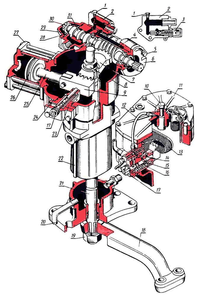
Fig. 49. Drejtues i rrymës:
1 - tapë; 2 - mbulesa e valvulave; 3 - vidhos rregulluese valvula e sigurisë; 4 - një krimb; 5 - një rrufe në qiellore e një prizë rregulluese; 6 - rregullimi i mëngës ekscentrike; 7 - sektori; në - një arrë; 9 - hekurudhor; 10 - vidhos rregulluese; 11 - mbulesa e sipërme; 12 - lubrifikimi i tubit të naftës mbështetje e sipërme; 13 - filtri; 14 - valvula për uljen e presionit; 15 - valvula e kontrollit; 16 - dredha e sensorit; 17 - një fluturues i vinçit; 18 - bipod; 19 - një arrë; 20 - prizë kullimi; 21 - një bosht rrotullues; 22 - rasti; 23 - hekurudha e theksit; 24 - shtrimin e rregullimit; 25 - aksione; 26 - pistoni; 27 - mbulesa e cilindrit të përparëm; 28 - kushineta me shtytje; 29 - një mbulesë; 30 - një arrë; 31 - dredha.
Krimbi 4 është montuar në një mëngë të çuditshme 6 në dy kushineta topin radial. Kushinetat e jashtme të kushinetave janë montuar në mëngë 6 me një pastrim të vogël, kështu që krimbi së bashku me rruzullin 31 të fiksuar në krahun e tij kanë aftësinë të lëvizin në drejtimin boshtor. Kushineta speciale me rrahje me rrahje 28 janë instaluar në të dy anët e valvulës, të cilat sigurojnë lëvizje boshtore të valvulës dhe parandalojnë rrotullimin e saj të përbashkët me krimbin. Kafshët mbajtëse përballë spoolit janë rritur diametrat e jashtëm dhe veprojnë si rondele në qendër. Një arrë sferike 30 shtyp kushinetat kundër dredhëzës.
Boshti rrotullues 21, në pjerrësitë e rërës së të cilit sektori 7 dhe bipodi janë të fiksuar 18, rrotullohet në tre kushineta: dy tufa strehimi dhe në mbulesën e sipërme 11. kushineta e sipërme lubrifikohet me vaj që vjen përmes vijës së naftës 12.
në lëvizje drejtvizore të traktorit, bobina 4 (Fig. 50) është në pozicion neutral dhe mbahet nga tre palë rrëshqitëse 5 të vendosura në një kënd prej 120 °. Ata janë duke shpërthyer me burimet e qendrës 6 dhe për këtë arsye kërkojnë të mbajnë predhat e brendshme të kushinetave të lidhura me dredhëzën në të njëjtin nivel me skajet e strehës së drejtimit të energjisë 22 dhe kapakut të shpërndarësit 2. Vaji nga pompa hyn në zonën qendrore të rrotullës dhe, pasi që gjerësia e tij është e vendosur tashmë në strehimin e shpërndarësit, ai përkulet rreth tij, derdhet në daljet ekstreme të kullimit dhe pastaj përmes valvulës për zvogëlimin e presionit 1 dhe filtri 8 shkarkohet në rezervuar - strehimi i përforcuesit hidraulik.
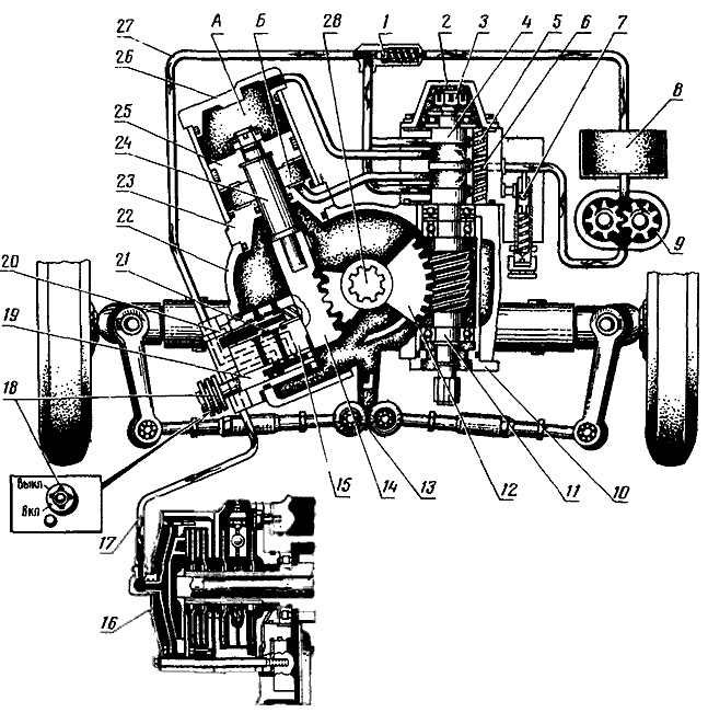
Fig. 50. Skema e drejtimit të energjisë dhe bllokimi diferencial:
A - zgavër pa shufër; B - zgavra e shufrës së cilindrit; 1 - valvula për uljen e presionit; 2 - kopertina e distributorit; 3 - një arrë; 4 - dredha; 5 - rrëshqitës; 6 - pranverë në qendër; 7 - valvula e sigurisë; 8 - filtër; 9 - pompë; 10 - mëngë ekscentrike; 11 - një krimb; 12 - sektori; 13 - bipod; 14 - hekurudhor; 15-theksi i qafës; 16 - bllokimi i cilindrave; 17 - sensori i linjës së vajit; 18- shami dore e vinçit; 19 - trokitje e lehtë e sensorit; 20 - sondë; 21 - rrotullimi i sensorit; 22 - strehimi i drejtimit të energjisë; 23 - një mbulesë e pasme e cilindrit; 24 - aksione; 25 - një pistoni; 26 - mbulesa e cilindrit të përparëm; 27 - kyçi i valvulave të linjës së vajit; 28 - boshti rrotullues.
Konsideroni ta ktheni traktorin në të djathtë. Rrotullimi i timonit përmes ingranazhit drejtues transmetohet te krimbi 11. Nëse rezistenca ndaj rrotullimit të rrotave të drejtimit është e lartë, në krimb lind një forcë aksiale që tejkalon forcën kompresive të burimeve të përqendrimit 6. Krimbi ka një spirale të drejtë, prandaj, kur rrotullohet në të djathtë, mbështetet në sektorin 12, i cili pengohet nga rezistenca e rrotave si një vidhos në një arrë të fiksuar, ajo lëviz së bashku me bobinën 4 të fiksuar në krahun e saj përpara, drejt kapakut 2 ( goditje maksimale dredha në një drejtim është 1.2 mm, goditja në fillim të mbivendosjes së rripave të strehimit të shpërndarësit është 0.6 mm). Në këtë rast, shpatulla e mesme në rrotull do të bllokojë kalimin e vajit nga pompa në brazdën e kullimit të përparmë. Në të njëjtën kohë, jaketa ekstreme e rrobës do të bllokojë daljen e vajit nga zgavra e cilindrit B në gropën e kullimit të poshtëm në strehën e shpërndarësit. Përkundrazi, jakja tjetër ekstreme e dredhëzës do të rrisë lëpushën për kullimin e vajit nga zgavra A e cilindrit në nënshartesë në strehën e shpërndarësit. Vaji nga brazda e shkarkimit të mesëm përmes tubacionit do të shkojë në zgavrën B të cilindrit. Zgavra B e cilindrit do të fillojë të rritet, pistoni 25 së bashku me shufrën 24 dhe rafti 14 do të tërhiqet dhe, duke vepruar në sektorin 12, kthen boshtin 28 dhe bipodin 13 në të majtë (përgjatë traktorit). Bipodi do t'i kthejë rrotat drejtuese në të djathtë përmes shufrave kravatë të trapezoidit drejtues.
Rrotullimi i rrotave drejtuese të traktorit në të djathtë do të vazhdojë për aq kohë sa shoferi i traktorit rrotullon timonin. Për më tepër, shpejtësia e rrotullimit të rrotave të traktorit është në përpjesëtim me shpejtësinë e rrotullimit të timonit. Sapo rotacioni i timonit të ndalet, pellgu nën veprimin e burimeve 6 të rrëshqitësve 5 futet në pozitë neutrale. Kjo lehtësohet edhe nga forca që lind në dhëmbët e krimbit nga ana e sektorit dhe drejtohet në drejtim të kundërt me zhvendosjen boshtore të krimbit. Ky është veprimi vijues i përforcuesit hidraulik.
Në mënyrë të ngjashme, traktori rrotullohet në të majtë.
në kushte normale presioni i vajit në sistemin e amplifikatorit nuk i kalon 2 ... 4 MPa (20 ... 40 kgf / cm²): Sidoqoftë, në pozicionet ekstreme të rrotave, kur rrotullimi i tyre i mëtejshëm është i kufizuar nga pistoni 25 ndalja në kapakun e cilindrit ose kur rezistenca ndaj rrotullimit të rrotave rritet për shkak të për shkak të kushteve të rënda të rrugës (matës i thellë, tokë e lirshme, etj.), presioni në sistem rritet derisa të aktivizohet valvula e sigurisë 7. Duke anashkaluar cilindrin, vaji do të shkrihet në vijën e kullimit nën presionin për të cilin është rregulluar valvula e sigurisë. Presioni i hapjes së valvulës së sigurisë rregullohet nga tensioni i pranverës. Duhet të jetë 83 -9.3 MPa (83 ... 93 kgf / cm²).
Nëse rezistenca kthyese e rrotave është e vogël (ngasja në rrugët e asfaltuara në shpejtësi të lartë), atëherë rotacioni kryhet pothuajse pa pjesëmarrjen e sistemit hidraulik të amplifikatorit. Në këtë rast, forca boshtore mbi krimbin që ndodh kur traktori është kthyer është më pak se forca e para-kompresimit të burimeve qendërzuese 6 të rrëshqitësve 5. Kthimi i timonit drejtues të shoqëruar me drejtimin me krimbin 11 siguron një transmetim të drejtpërdrejtë të lëvizjes në trapezoidin drejtues përmes sektorit 12, boshtit rrotullues 28 dhe bipodit 13 . Në këtë rast, burimet e përqendrimit nuk kompresojnë, krimbi së bashku me bobin në drejtim aksial nuk lëviz, dhe vaji në shpërndarësin nga zgavra e injektimit derdhet në kullues pa ndikuar në pistonin e cilindrit. Në këtë rast, sektori 12 lëviz shufrën dhe pistonin e cilindrit nëpër hekurudhor 14, dhe vaji nga zgavra A dhe B shkarkohet në strehën e rezervuarit të energjisë përmes prurjeve të kullimit të hapur në shpërndarës.
Në rast të transportit të traktorëve me motor boshe në tërheqje, një dështim të pompës ose një mosfunksionim tjetër i drejtimit të energjisë, kontrolli i traktorit nuk cenohet, megjithatë, përpjekja në timon rritet ndjeshëm. Në këtë rast, rotacioni i traktorit kryhet vetëm për shkak të përpjekjeve të bëra nga operatori i traktorit në timon. Kur ngasni rëndë kushtet e rrugës lëvizja e lirë e timonit gjithashtu rritet ndjeshëm, pasi që para fillimit të transmetimit të rrotullimit në sektor, krimbi në çdo drejtim duhet të kalojë një distancë prej 1.2 mm. Përveç kësaj, kjo goditje është rritur për shkak të deformimit më të madh të pjesëve të ingranazhit drejtues që transmetojnë çift rrotullues në rritje nga timoni.
Sensori automatik i kyçjes diferencial (ABD) montuar në drejtuesin e energjisë. Kontrollon përfshirjen e tufës së bllokimit kur traktori po lëviz drejt dhe jashtë për të zhbllokuar diferencialin kur kthehen rrotat e përparme.
Sensori është vendosur në ndalesën 23 (shiko Fig. 49) të raftit 9 dhe përbëhet nga një rrotull 16, një valvul 15, një kontroll me një shami dore 17, një majë shkruese 20 (shiko Fig. 50). Sistemi ABD gjithashtu përfshin një valvul të parregulluar të presionit të rregulluar 1 (pos 14 në figurën 49), i cili mban një kokë presioni prej 0.7 ... 1.0 MPa (7 ... 10 kgf / cm²) në sistemin hidraulik të vetë-mbylljes hidraulike në një temperaturë vaji prej 40. ..70 ° C
ADB është ndezur duke e kthyer dorën e dorës 18 (shiko Fig. 50) në mënyrë që foleja në dorën e dorës të përkojë me shkronjat "ON" që janë rrëzuar në aeroplanin e kapakut të ndalesës. Kur bllokimi automatik është fikur, slota përkon me shkronjat "OFF".
Në pozicionin e dorës "ON", diafragma e cilindrit 16 të pajisjes bllokuese diferenciale është e lidhur përmes një tubi vaji 17 në vijën e presionit të valvulës për uljen e presionit 1. Disqet ngjeshen përmes diafragmës dhe kryqi diferencial bllokohet nga ingranazhi i makinës përfundimtare të majtë.
Kur rrotat drejtuese kthehen në një kënd që tejkalon 13 °, hekurudha 14 do të lëvizë në mënyrë që shtytësi i valvulës rrëshqitëse të lëshojë brazdën në hekurudhë dhe lëviz valvulën e rrëshqitjes 16 (shiko Fig. 49), e cila lidh zgavrën e brendshme të valvulës 15 me një kullim në rezervuar. Kështu, linja e presionit dhe zgavra e diafragmës janë të lidhura me kullimin. Presioni i vajit në zgavrën e diafragmës bie, dhe tufa diferenciale e kyçit shkëputet, e cila lejon që traktori të kthehet me shpejtësi të ndryshme të rrotullimit të rrotave të pasme të djathtë dhe të majtë.
Në pozicionin e shiritit të dorës "OFF", valvula 15 është e rrotulluar në mënyrë që zgavra e brendshme e vinçit dhe zgavra e diafragmës të lidhen me kullimin. Prandaj, në këtë pozicion diferenciali nuk bllokohet.
Duke përdorur kutinë 20 (shiko fig. 50) gjeni pozicionin mesatar të raftit 14 për instalimin e rrotave të përparme të traktorit kur rregulloni shufrat lidhës të trapezoidit drejtues. Hekurudha do të jetë në pozicionin e mesëm kur sonda 20 është sa më e afërt me aeroplanin ndalues.
Kyçja kontrollohet nga doreza 10 (Fig. 51) e vendosur në kabinë dhe është e lidhur me një kabllo 5 në shiritin e dorës 3 të vinçit të sensorit. Doreza 10 ka tre pozicione:
- Pozicioni I - "Kyçja diferenciale është e fikur" - doreza është në pozicion ekstrem përpara. Rreziku në telen e dorës përkon me rrezikun "OFF" në kapakun e sensorit;
- Pozicioni II - "Kyçja automatike diferenciale është e ndezur" - doreza 10 zhvendoset prapa përgjatë traktorit në pozicionin e mesëm dhe fiksohet duke e kthyer atë 90 ° në drejtim të akrepave të orës. Rreziku i vinçit përkon me rrezikun e "ON";
- Pozicioni III - “Kyç diferencial diferencial” - doreza shtrihet në pozicionin e saj ekstrem të pasmë dhe mbahet nga dora e operatorit të traktorit. Vinçi është kthyer në drejtim të akrepave të sahatit në ndalesë dhe, pavarësisht nga pozicioni i hekurudhës, lidh linjën e presionit të valvulës 1 për uljen e presionit 1 (shiko fig. 50) me cilindrin e bllokimit 16, duke parashikuar që rrotat e pasme të jenë të kyçura. Pasi që operatori i traktorit lëshon dorezën, kthehet në pozicionin 1 nën veprimin e burimit të kabllit, dhe diferenciali është i zhbllokuar.
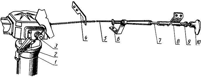
Fig. 51. Kontrolli i bllokimit diferencial:
1- kllapa pranverore; 2 - pranvera; 3 - shami dore e vinçit; 4 dhe 6 - kllapa për montim kabllor; 5 - kabllo; 7 - një bërthamë; 8 - shufra udhëzuese; 9 - vula e murit të përparmë të kabinës; 10 - trajtuar.
Pompë drejtuese e rrymës. sistemi hidraulik veshje drejtuese të përdorura pompë vaji NSh 10-3-L GOST 8753-71. simbole: 10 - zhvendosje (furnizimi teorik i naftës në cm³ për një revolucion të boshtit të pompës); 3 - dizajni i tretë në përputhje me GOST 8753-71; Rrotullimi i të majtës L (në të kundërt nga ora e djathtë kur shikohet nga ana e makinës). Shkalla e rrjedhës vëllimore të pompës është -20 l / min në 2200 rpm.
Pompë përbëhet nga një strehim 4 (Fig. 52), një mbulesë 1 dhe një njësi pompimi, e cila përfshin një makinë 5 dhe një ingranazh të drejtuar 7, dy kushineta 3, dy pranga me figura 6, pllaka 9, vula. Kushinetat 3 shërbejnë si kushineta të ingranazheve të ingranazheve, dhe gjithashtu vulosin sipërfaqet fundore të ingranazheve. Konturet e jashtme të kushinetave janë në formën e numrit 8. Në secilën kushinetë, bëhen dy karrige për ingranazhet pinion. Në grooves në anën e kundërt nga ingranazhet, ka prangat kaçurrel 6 që kufizojnë zonën presion të lartë nga zona presion i ulët. Bashkimi i strehës 4 me mbulesën 1 është mbyllur me një unazë 2 të seksionit kryq rrethor, i cili është hedhur në një lule ovale mbi strehimin.
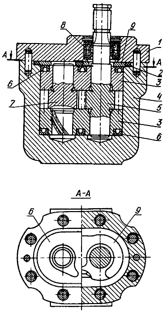
Fig. 52. Pompë drejtuese e rrymës:
1 - mbulesë; 2 - një unazë nënshkrimi; 3 - kushineta; 4 - rast; 5 - veshje pinion; 6 dhe 8 - pranga; Veshje 7 - e drejtuar; 9 - pjatë.
Fundi i makinës së ingranazhit pinion 5 është mbyllur me dy pranga kornizë 8, të cilat përjashtojnë rrjedhën e vajit nga sistemi përforcues hidraulik në kthesën e motorit.
Për të zvogëluar rrjedhën e vajit nëpër boshllëqet midis skajeve të ingranazheve dhe kushinetave 3, pompa siguron ngarkim automatik të kushinetave në skajet e ingranazheve me presion të furnizuar nga zona e shkarkimit në zgavrat e kufizuara nga prangat në formë 6. Meqenëse zona e kësaj zone është më e madhe se zona e zonës së presionit të lartë që vepron në dhëmbë ingranazhe për kushineta, këto të fundit shtypen kundër skajeve të ingranazheve me një forcë që tejkalon forcën e nxjerrjes së tyre nga dhëmbët e ingranazheve. Kjo siguron një presion të vazhdueshëm të kushinetave në skajet e ingranazheve, duke eliminuar kështu boshllëqet midis kushinetave dhe skajeve të ingranazheve.
Pincat e ingranazheve lubrifikohen me vaj, i cili çohet në grooves spirale në tufat e kushinetave 3 nga zgavra e thithjes. Pincat e ingranazheve lubrifikohen dhe ftohen me këtë vaj, pas së cilës kthehen përsëri në zgavrën e thithjes.
Mirëmbajtja e drejtimit konsiston në monitorimin periodik të nivelit të naftës në banesë dhe mungesën e rrjedhjeve në lidhjet përforcuese hidraulike, gjendjen e lidhjeve të filetuara të drejtuesit, shufrat e drejtimit, sigurimin e sektorit, bifodit dhe levave të lëkundjes; në lubrifikimin në kohë të nyjeve kardan drejtuese, rrjedhje filtri i vajit, ndërrimi i naftës, kontrollimi dhe rregullimi i lëvizjes pa pagesë të timonit, zgjidhja e shpejtë e mosfunksionimeve që mund të shfaqen gjatë operimit.
Duhet të sigurohet që kur kontrolloni nivelin e vajit, duke skuqur filtrin e vajit dhe mbushni vajin, nuk futet asnjë papastërti në sistemin përforcues hidraulik.
Skuqja e filtrit të vajit prodhuar çdo 960 orë në këtë sekuencë.
- Shkëputni vijën e vajit 12 (Fig. 49) për lubrifikimin e mbështetëses së sipërme nga kapaku 11 dhe valvula lehtësuese e presionit 14.
- Hiqeni kapakun e sipërm 11, për të cilin hiqni të gjitha bulonat dhe, duke i kthyer në mënyrë të barabartë dy prej tyre në vrimat e filetuara, ngrini.
- Shkëputni dy linjat e mbetura të naftës nga valvula zvogëluese e presionit 14 dhe, duke mbajtur filtrin 13 me dorë, kthejeni valvulën derisa filtri të jetë i lirë.
- Shpëlarjeni filtrin në benzinë \u200b\u200bose karburant dizelduke pastruar zgavrën e saj të brendshme të papastërtisë. Njëkohësisht me larjen e filtrit, shtrëngoni arrën 8 duke siguruar sektorin 7 në boshtin 21 dhe kontrolloni ingranazhet e sektorit të raftit.
Nëse hendeku midis dhëmbëve të sektorit dhe slats është më shumë se 0.3 mm. ingranazhet duhet të rregullohen.
Për ta bërë këtë, hiqni katër bulonat që sigurojnë ndalimin 23 të hekurudhës ABD dhe, duke nxjerrë copëzat 24 në çifte, zvogëloni pastrimin në rrjetë në 0,1 ... 0.3 mm. Hendeku midis dhëmbëve të sektorit dhe slats matet duke përdorur një matës të ndjerë.
Filtri është instaluar në rend të kundërt. Pasi të keni instaluar kapakun 11, pasi të keni zbërthyer më parë arrën e kyçit, shtrëngoni bulonën 10, e cila rregullon lëvizjen boshtore të boshtit rrotullues 21., pastaj kthejeni bulonën rreth 1 / 10-1 / 8 nga ana e tij dhe kundërviheni.
Rregullimi i shtrëngimit të krimbave - sektori dhe shtrëngimi i arrës së krimbit. Rrotullimi i lirë i timonit kur kthehet rrotat drejtuese të një traktori që qëndrojnë në tokë të fortë me një motor nafte që funksionon duhet të jetë jo më shumë se 30 °. Nëse tejkalohet vlera e specifikuar, është e nevojshme të kontrolloni dhe, nëse është e nevojshme, të rregulloni nyjet e artikuluara të lidhjeve drejtuese, të shtrëngoni arrat e lidhësit dhe levat e lëkundjes në dështim. Nëse kjo nuk është e mjaftueshme, ju duhet të rregulloni pastrimin në sektorin e angazhimit - krimbin dhe shtrëngimin e arrës së krimbit.
Për të rregulluar angazhimin e sektorit - krimb, bëni si më poshtë.
- Me një çantë, ngre boshti i përparmë ose shkëputni lidhjet drejtuese nga bipodi.
- Lëshoni bulonën 5 duke siguruar mëngën ekscentrike rregulluese 6 dhe kthejeni atë në drejtim të akrepave të orës derisa krimbi të prehet në dhëmbët e sektorit. Pastaj, kur motori funksionon, rrotulloni timonin. Nëse bllokimi ndihet në angazhimin e sektorit të krimbave, është e nevojshme ta ktheni mëngën në të djathtë, derisa bllokimi të ndodhë kur ktheni timonin nga një pozicion ekstrem në tjetrin.
Forca në timon nuk duhet të kalojë 15 ... 25 N (1.5 ... 2.5 kgf) me shufrat drejtues të shkëputur nga bipodi dhe 30 ... 40 N (3 ... 4 kgf) me boshtin e përparmë . - Shtrëngoni bulonën 5 për fiksimin e mëngës rregulluese b dhe lidhni shufrat e lidhjes në bipod duke shtrënguar mirë arrat (ose hiqni boshtin e përparmë nga prizë nëse është kapur).
Një arrë e posaçme 30 me një fytyrë fundi sferik duhet të shtypë kafazet mbajtëse 28 kundër skajeve të rrotës 31. Prania e një hendeku midis rrotullës dhe kafazeve mbajtës për shkak të veshin, lirimi i arrës ose shtrëngimi jo i duhur gjatë instalimit mund të çojë në një rritje të kthesës së lirë të timonit, dhe nganjëherë në lëvizje të paqëndrueshme ( "Yaw") e traktorit, pasi në këtë rast spool mund të lëvizë spontanisht, duke drejtuar rrjedhën e vajit në një ose një zgavër tjetër të cilindrit, dhe të kthejë rrotat drejtuese të traktorit.
Për të shtrënguar arrë, është e nevojshme të kapni katër bulonat që sigurojnë shpërndarësin, të hiqni kapakun 29 me dy bulona të vendosura diametralisht, të rregulloni shpërndarësin në strehimin e përforcuesit hidraulik, pasi të keni vendosur më parë rondele nën kokën e bulonave në trashësinë e fllanxhës së kapakut 29 ose arra më të mëdha se diametri i bulonit. Tërhiqeni kunjin e kutisë dhe shtrëngoni arrën 30 derisa gara mbajtëse 28 të shtypet fort kundër rrotullës 31. Kontrolloni çift rrotulluesin shtrëngues, i cili duhet të jetë brenda 20 Nm (2 kgf-m). Pastaj zhbllokoni arrë 7 derisa vrima në krimb përputhet me pjerrësinë më të afërt dhe pinin.
Duhet të theksohet se shtrëngimi i tepërt i arrës rrit forcën në timon dhe mund të dëmtojë kushinetat e futjes 28. Një shenjë e shtrëngimit të duhur të arrës është mungesa e boshllëqeve midis karficës dhe kafazeve mbajtës dhe pështjellës që kthehet në pozicionin "neutral" nën pranverën 6 (shiko Fig. 50) pasi të keni ndaluar rrotullimin e timonit në të majtë. Kontrolli bëhet në motorin dizel të papunë. Pas kontrollimit, është e nevojshme të instaloni unazën o dhe kapakun 29 (shiko Fig. 49) dhe të shtrëngoni bulonat.
Rregullimi i valvulave të sigurisë. Shkelja e rregullimit të valvulës së sigurisë çon në një rritje
përpjekja e timonit, veçanërisht në kushte të vështira të rrugës. Për të kontrolluar rregullimin e valvulës në rreshtin nga pompa në shpërndarës ose në vend të prizës së vidhos 1 (shiko Fig. 49), është i lidhur një matës presioni me një shkallë të paktën 10 MPa (100 kgf / cm²). Pastaj, kur motori me naftë po funksionon me shpejtësinë maksimale, duke e kthyer timonin nga bllokimi në bllokues, ngrohni vajin në një temperaturë prej 50 ° C. Presioni në shkallën matës në pozicionin e majtë ose të djathtë të timonit duhet të jetë në rangun e 8.3 ... 9.3 MPa (83 ... 93 kgf / cm²). Nëse është më pak se kufijtë e specifikuar, duhet të hapni kapakun dhe ngadalë të ktheni vidhosin rregullues 3 me një kaçavidë derisa matësi i presionit të tregojë një presion prej 8.3 ... 9.3 MPa. Pas kësaj është e nevojshme të mbyllni vidhos 3 me një arrë bllokimi dhe të shtrëngoni kapakun.
28 Nëntor 2012 16:10Rregullimet e shërbimit dhe drejtimit të traktorëve MTZ dhe UMZ
Siguria, cilësia e punës dhe lodhja e shoferit varen nga gjendja e drejtimit në shumë aspekte. Prandaj, mirëmbajtja e drejtimit duhet të bëhet veçanërisht me kujdes.
Traktorët MTZ-80 dhe MTZ-82. Mirëmbajtja e drejtimit konsiston në kontrollimin në mënyrë periodike të nivelit të naftës në strehën e drejtimit të energjisë dhe zëvendësimin e tij, lubrifikimin e nyjeve kardanore të drejtimit, monitorimin e gjendjes së nyjeve të filetuara të makinës së drejtimit dhe shufrave drejtuese, levave bipod dhe rrotulluese, sigurimin e sektorit, kontrollimin dhe rregullimin e rrotullimit të lirë të timonit.
Kolona e drejtimit duhet të rregullohet për të shmangur dridhjet e mundshme në timon. Për këtë ditë, vidhosni arrën 12 (shiko Fig. 4.9) me dorë derisa kjo e fundit të kontaktojë me mëngë 10. Në këtë rast, duhet të zgjidhen boshllëqet në nyje. Pastaj hiqni arrën 12 rrotull e gjysmë dhe kthejni arrën 13.
Filtri i vajit lahet në këtë renditje. Ngrini veshjen. Shkëputni rreshtin e furnizimit të naftës 12 (shiko Fig. 4.10) nga kapaku 11 i valvulës për uljen e presionit 14. Hiqni kapakun, shkulni së pari dy bulonat duke e siguruar atë në strehën 22, dhe më pas, duke i përdorur ato si bulona të çmontimit, vidhosni bulonat në hapjet e çmontimit të kapakut dhe hiqni ajo. Shkëputni linjat e mbetura të naftës nga valvula për uljen e presionit 14. Duke mbajtur filtërin me dorë, kthejeni valvulën për heqjen e presionit dhe hiqni filtri i kullimit. Lani filtrin në karburant dizel.
Për të instaluar filtrat operacionet kryhen në renditje të kundërt.
Filtri është larë në TO-Z (960-1000 orë pune). Në të njëjtën kohë, shtrëngoni arrën 8 duke siguruar sektorin në boshtin rrotullues.
Në përforcuesin hidraulik, ata kontrollojnë: ingranazhin e sektorit të krimbit dhe sektorin-hekurudhor, shtrëngimin e arrës së krimbit, goditjen aksiale të boshtit rrotullues, valvulën e sigurisë, si dhe kontrollin e valvulës diferenciale të bllokimit.
Angazhimi në sektorin e krimbave dhe shtrëngimi i arrës së krimbit rregulloni në sekuencën vijuese. Lidhni traktorin në mënyrë që rrotat e përparme të mos prekin tokën. Pastaj lirojeni shtrëngimin e bulonit rregullues 5, vendosni çelësin në gropën e mëngës 6 dhe kthejeni atë në drejtim të akrepave të orës në ndalesën e dhëmbëve të krimbit dhe sektorit (ndërsa bipodi 18 duhet të jetë në pozicionin e mesëm). Mëngu është kthyer në drejtim të akrepave të sahatit në mënyrë që të rrotullohet 10-12 mm në diametër të jashtëm. Shtrëngoni bulonën 5. Filloni motorin dhe kontrolloni për bllokim në rrjetën e sektorit të krimbit kur ktheni timonin në të dy drejtimet në ndalesë. Nëse në të njëjtën kohë ka konfiskime, atëherë është e nevojshme të rrisni zbritjen në fejesë duke liruar bulonën 5 dhe duke e kthyer mëngën 6 shtesë në drejtim të akrepave të orës.
Përpjekja në timon nuk duhet të kalojë 30-40 N.
Shtrëngimi i arrës sferike 30 të krimbit konsiston në shtrëngimin e saktë të fut kushineta topi 28 për të siguruar ngjeshje normale të skajeve të rrotullës 31 nga unazat e kushinetës.Kjo varet kryesisht nga kjo rregullim punë e mirë drejtues energjie. Shtrëngimi i tepërt i arrës 30 mund të shkaktojë që lëkura të rritet dhe të rrisë forcën e kthimit. Hapësirat midis kushinetave dhe bobinave çojnë në një rritje të kthesës së lirë të timonit, si dhe të dridhjeve të rrotave, pasi në këto kushte spooli mund të lëvizë në mënyrë arbitrare, duke ndryshuar në përputhje me rrethanat drejtimin e rrjedhës së vajit në një ose një zgavër tjetër të cilindrit të pistonit.
Para se të shtrëngoni arrë 30, hiqni katër bulonat që sigurojnë shpërndarësin, hiqni kapakun 29. Bashkangjitni shpërndarësin me dy bulona të vendosura diametralisht në strehën e përforcuesit hidraulik, vendosni një grup rondele (ose arrë) nën kokat e bulonave, trashësia (ose lartësia) e së cilës është e barabartë me trashësinë e fllanxhës së kapakut 29. Shtrëngoni, më parë duke e unfastifikuar arrën me një moment të forcës 20 Nm Në këtë rast, unazat e kushinetave 28 duhet të shtypen fort në skajet e rrotullës 31. Atëherë, arrë fiket me 1 / 10-1 / 12 e një kthesë për të lidhur rreshtin e arrës për kunjën e mollëzës dhe vrimën në krimb dhe qepën e arrës. Dy bulona janë kthyer, të dehur në trup, vendosni kapakun 29 në vend dhe rregulloni shpërndarësin
Ingranazhe sektori rregulloni gaskets 24 nën fllanxhin e shinave të theksit 23. Në këtë rast, hendeku midis ndalesës dhe hekurudhës 9 duhet të jetë 0,1-0,3 mm. Duke kontrolluar këtë boshllëk, duhet të shtrëngoni hekurudhën 9 në sektorin 7.
Goditje boshtore e boshtit rrotullues rregulloni në sekuencën vijuese. Lëshojeni shtrëngimin e arrës së kyçjes dhe vidhosni vidhën rregulluese 10 gjatë gjithë rrugës në skajin e boshtit. Pastaj kthejeni bulonën 10 nga 1 / 8-1 / 10 të një kthesë dhe kundërviheni atë me një arrë.
Valvula e sigurisë kontrollohet si më poshtë. Në vijën e shkarkimit ose brenda mbulesë valvulash në vend të prizës 1, është i lidhur një matës presioni me një shkallë prej 0 deri në 10 MPa. Ata fillojnë motorin dhe kthejnë timonin nga një pozicion ekstrem në një tjetër. Me shpejtësi maksimale bosht me gunga naftë, sillni temperaturën e vajit në sistemin hidraulik në 50 + 5 ° C. Në këtë rast, presioni duhet të arrijë 8.8 MPa.
Nëse matësi i presionit është më i vogël, shtoni presionin në vlerat e kërkuara duke e kthyer ngadalë vidhën 3. Pas rregullimit, vidhos 3 duhet të jetë i kyçur me një arrë dhe kapaku i instaluar. Një shenjë e një mosregjistrimi të valvulës së sigurisë është një rritje e forcës drejtuese.
Rrota pa leje kontrolluar në parkingun me motorin që funksionon. Sidoqoftë, nuk duhet të kalojë 20 °. Nëse loja pa timon është më e madhe, kontrolloni pastërtitë në lidhjet e makinës së drejtimit dhe, nëse është e nevojshme, shtrëngoni arrat e montimit të bipodit dhe sektorit, krahët e boshtit të boshtit të përparme dhe lidhjet e lidhjes së drejtimit, shtrëngoni arrën e krimbit, rregulloni sektorin e krimbit, raftin sektor dhe ingranazhet boshtore goditje rrotulluese e drejtimit të energjisë.
Shtë e nevojshme të monitoroni rregullisht nivelin e vajit në sistemin hidraulik të drejtimit. Nëse niveli i vajit është më pak se rreziqet më të ulëta në njehsorin e naftës, veproni me traktorin rreptësisht e ndaluar.
Gjatë ndërrimit të vajit, filtri i hyrjes duhet të lahet në të njëjtën kohë. Pas ndërrimit të vajit, sistemi hidraulik drejtues pompohet në këtë renditje. Lidhni boshtin e përparmë derisa rrotat e përparme të zbresin nga toka. Motori është nisur dhe, me një shpejtësi të ulët të rrotullimit të boshtit të motorit, timoni është kthyer në pozicione ekstreme 8-10 herë (në fillim ngadalë, pastaj shpejt), ndërsa nuk e mban atë në pozicione ekstreme. Pastaj kontrolloni nivelin e vajit dhe, nëse është e nevojshme, shtoni atë në shenjën e sipërme të njehsorit të vajit.
shpërndarësështë e nevojshme të hiqni dhe riinstaloni në rast të zëvendësimit të unazave të saj nënshkrimin dhe pjesëve të larjes. Kur instaloni shpërndarësin, kryeni sa vijon. Kontrolloni praninë e unazave o në skajet e shpërndarësit dhe pozicionin e rrotullës 31 në strehën e tij. Dredha duhet të jetë e instaluar në mënyrë që faqja e saj fundore me një kamxhik në diametër të jashtëm të drejtohet në strehimin e përforcuesit hidraulik. Instalimi i kundërt i rrotullës do të çojë në një rritje të mprehtë të përpjekjes së rrotullimit.
Instaloni shpërndarësin pa mbulesën e jashtme 29 dhe fiksojeni atë në strehën e përforcuesit hidraulik me dy bulona të vendosura diametralisht, duke vendosur një grup rondele nën kokat e bulonave, trashësia e së cilës është e barabartë me lartësinë e kapakut. Vendoseni kushinen e futjes 28 në rondele konin dhe shtrëngoni arrën sferike 30 në përputhje me rekomandimet e dhëna më lart. Një shenjë e shtrëngimit të duhur të arrës është mungesa e boshllëqeve midis rrotullës dhe unazave mbajtëse dhe prapambetjes së timonit (kthimi i rrotës në pozicionin neutral) pasi të ndaloni rrotullimin e tij në të majtë.
Traktorët MTZ-100 dhe MTZ-102. Periodikisht, nëse vlera loje e lejueshme timoni bëhet më shumë se 25 °, është e nevojshme të pomponi sistemin drejtues në këtë sekuencë. Vendosni boshtin e përparmë derisa rrotat e përparme të mos bien nga sipërfaqja e mbështetësit. Motori është nisur dhe, me një shpejtësi të ulët të rrotullimit të boshtit të motorit, timoni është kthyer në pozicione ekstreme 8-10 herë (në fillim ngadalë, pastaj shpejt), ndërsa nuk e mban atë në pozicione ekstreme.
Traktorë UMZ. Drejtues i rrymës. Rrotullimi normal i lirë i timonit gjatë lëvizjes së traktorit në vijë të drejtë nuk duhet të kalojë 15 °. Nëse është mbi 30 °, është e nevojshme të rregulloni drejtuesin.
Fillimisht, artikulacioni i lidhjes së drejtimit dhe zhdoganimi në kushinetat e bllokuar të rrotave drejtuese janë rregulluar. Nëse lëvizja e lirë e timonit pas kësaj mbetet e rritur, kontrolloni pastrimin boshtor në kushinetat e mbyllura të krimbit të ingranazhit (shiko Fig. 4.18). Për ta bërë këtë, shkëputeni tërheqje gjatësore 7 nga bipodi 8 dhe krimbi 4 është shkëputur nga rul, duke e kthyer timonin në çdo drejtim. Pastaj shkundni boshtin e timonit në drejtimin aksial. Nëse lëvizja e boshtit është e dukshme, zvogëloni pastrimin në kushinetat e rërësa të manaferrës duke hequr një pjesë të shims 5 nga nën mbulesën e poshtme të mekanizmit drejtues. në rregullimi i duhur kushinetat e krimbave të timonit duhet të rrotullohen nga një forcë prej 3-8 N.
Pas kësaj, vendoseni rrotullën kundër mesit të krimbit dhe, duke shkundur bipodin, kontrolloni hendekun midis rulit dhe krimbit. Pastrimi normal duhet të jetë i tillë që skaji i poshtëm i bipodit të lëvizë kur lëkundet jo më shumë se 0.15 mm. Nëse hendeku është më i madh, atëherë është e nevojshme ta rregulloni atë.
Rregulloni lidhjen e krimbit me rrotull në sekuencën vijuese.
Hiqni mekanizmin e drejtimit, hiqni majën 18 të vidhës rregulluese dhe hiqni rondelën 17.
Vidhosni vidhën rregulluese 16 derisa boshllëku në fejesë me pozicionin e rrotullës kundër mesit të krimbit të mungojë, dhe timoni i rrotës rrotullohet nga një forcë prej 15-22 N.
Pastaj vendosni rondelën në vend, rregulloni atë me një arrë dhe vendosni veshjen drejtuese në traktor.
Drejtues i energjisë. Hendeku në angazhimin e sektorit të krimbave duhet të korrespondojë me boshllëkun në sipërfaqen anësore të thërrmijave të krimbit me një pozicion mesatar bipod prej 0.6-0.7 mm (këndi 4-6 °). Për ta rregulluar atë, hiqni bulonën 27 (shiko Fig. 4.19) me 2-3 kthesa dhe ktheni mëngën 2 në drejtim të akrepave të orës për të zvogëluar hendekun ose në të djathtë për ta rritur atë. Pas rregullimit, bulona 27 është e mbështjellur.
Hendeku i dhëmbit ndërmjet sektorit 25 dhe hekurudhës 4 duhet të korrespondojë me një hendek prej 0,1-0,3 mm ndërmjet rrafshit të montimit të fllanxha ndalës b dhe strehimit 3. Hendeku është vendosur duke zgjedhur shims 5. Për të përcaktuar trashësinë e gaskets, përcaktohet hendeku midis planeve të montimit të ndalesës 6 dhe strehimit 3 kur përfshirja pa pastrim e raft 4 me sektorin 25. Trashësia e gaskets duhet të jetë 0,1-0,3 mm më shumë.
Drejtimi boshtor i rrotullimit të lirë të boshtit rrotullues rregullohet me një vidë në strehën e ingranazhit drejtues. Për ta bërë këtë, lëshoni butonin e vidhos dhe shtrëngoni atë derisa të ndalet, pastaj kthejeni përsëri 1 / 10-1 / 8 të kthesës dhe mbylleni atë me arrën e kyçit. Për funksionimin normal të përforcuesit hidraulik, është e rëndësishme që të shtrëngoni si duhet kushinetat e futjes me një arrë sferike 20. Shtrëngimi i tepërt i arrës mund të shkaktojë që lëkura të rrallohet dhe të rritet forca e kthesës.
Para se të shtrëngoni arrat, fiksoni shpërndarësin në strehën e përforcuesit hidraulik me dy bulona, \u200b\u200bpasi të vendosni rondelet nën kokën e bulonave në trashësinë e fllanxhës së kapakut 19. Shtrëngoni arrën e krimbit me një çift rrotullues 20 Nm, ktheni atë 1/1 2-1 / 8 kthesat derisa vrima në krimb përkon me slotën nën pin pinter dhe arrë ari. Pastaj rezultojnë dy bulona të fiksimit të shpërndarësit në rastin, kapaku 19 është instaluar dhe shpërndarësi është i fiksuar me besueshmëri në përforcuesin hidraulik.
Rregullimi i valvulës së sigurisë është i ngjashëm me rregullimet e traktorëve MTZ-80 dhe MTZ-82 të përshkruara më lart.
Kur rregulloni varet e shufrës së kravatë, priza rregulluese është e pastruar, e mprehur në ndalesë, dhe pastaj zhbllokoni atë derisa brazda e prizës të përkojë me vrimat e kunjave të kutisë në lidhësin dhe pinin e bazës. Kur rregulloni varet e shufrave drejtuese tërthore dhe shtytëse, priza rregulluese është e pa mbërthyer, atëherë ajo është e mbështjellur në mënyrë që kunjja e topit të rrotullohet në oxhaku kur të aplikohet 3-7 N · m.
Traktorë YuMZ-8070. . .YUMZ-8280. Vaji në sistemin GORU duhet të ndryshohet gjatë sezonit mirëmbajtje, dhe nëse sistemi është i mbushur me vaj jashtë sezonit, çdo 1000 orë punë të motorit.
Elementi filtër i MOUNTAIN duhet të ndryshohet çdo 500 orë të funksionimit të traktorit.
Për të ndryshuar elementin e vajit dhe filtrit, bëni sa më poshtë:
- kthejeni timonin në të djathtën e djathtë derisa të ndalojë;
- hiqni kapakun 1 (Fig. 4.44), hiqni prizën 3 dhe kullojeni vajin nga rezervuari 2;
- shkëputni dy bulonat 5 duke siguruar filtrin në kllapa dhe hiqni filtrin;
- hiqni dy bulonat e mbetura që sigurojnë filtrin në kllapa dhe hiqni kapakun;
- hiqni elementin e filtrit me valvulën e anashkalimit nga kutia. Shtë e ndaluar të rrotullohet trupi i valvulës anashkaluese nëpër fije, pasi kjo do të shkelë rregullimin e tij;
- lyej strehimin e filtrit dhe - valvula e anashkalimit, zëvendësoni elementin e filtrit;
- montoni dhe instaloni filtrin në traktor, lidhni tubacionet e naftës me të;
- shtoni vaj në rezervuarin 2 në shenjën kryesore në matësin e vajit;
- filloni motorin dhe ktheni timonin disa herë majtas dhe djathtas derisa të ndalojë;
- ndaloni motorin dhe shtoni vaj në rezervuar me timonin në pozicionin e mesëm;
Pas mbushjes së sistemit, niveli i vajit në rezervuar duhet të jetë midis shenjave të sipërme dhe të poshtme të njehsorit të vajit.
Rregullimi i drejtimit të energjisë supozon rregullimet vijuese: Angazhimi i sektorit të krimbave, angazhimi sektor-hekurudhor, shtrëngimi i arrës së krimbit, goditja aksiale e boshtit rrotullues, valvula e sigurisë, si dhe kontrolli i karin diferencial. Për të rregulluar angazhimin e sektorit të krimbave, lironi bulonën, futni çelësin në gropën e fllanxhes së mëngës, ktheni mëngën në drejtim të akrepave të orës (përgjatë traktorit) derisa të ndalet në pozicionin e mesëm të bipodit, pastaj kthejeni atë 10-12 mm në të kundërt të akrepave të akrepave të orës, përgjatë diametrit të jashtëm të fllanxhës. Shtrëngoni një rrufe në qiell, filloni motorin dhe bindeni se bllokoni kur ktheni një timon në të dy drejtimet kundër ndalimit. Nëse është e nevojshme, rrisni zbritjen në fejesë duke e kthyer mëngën në të djathtë, derisa të ndodhë bllokim.
Për të rregulluar angazhimin sektor-hekurudhor, zvogëloni trashësinë e grupit të shims-it nën fllanxha ndalese derisa të merret një hendek prej 0.1-0.3 mm midis ndalesës dhe raftit. Kur kontrolloni zhdoganimin, shtyni hekurudhat në sektor. Arra sferike e krimbit shtrëngon kushinetat e futjes. Shtrëngimi i duhur kushineta fut është gjendje kritike funksionimi normal i përforcuesit hidraulik.
Shtrëngimi i tepërt i arrës mund të shkaktojë ngulitje të rrotullës dhe forcë të pabarabartë kthyese. Para se të shtrëngoni arrë, rregulloni shpërndarësin me dy bulona, \u200b\u200bpasi më parë keni vendosur rondele nën kokën e bulonave në trashësinë e fllanxhes së mbulesës. Shtrëngoni arrën e krimbit në 2 kgf / m (20 N-m), hiqni atë nga kthesa 1/12 - 1/10 derisa vrima në krimb të përkojë me slotën për kunjën e arrave dhe të ziej arrën. Rezultoni dy bulona të fiksimit të shpërndarësit në rastin, vendosni një mbulesë dhe rregulloni me siguri shpërndarësin.
Për të rregulluar goditjen boshtore të boshtit rrotullues, lirojeni arrën e kyçjes, shtrëngoni rrufe rregulluese deri në skajin e boshtit, pastaj zhvisheni nga 1 / 8-1 / 10 e një kthesë dhe mbylleni me një arrë bllokimi. Për të rregulluar valvulën e sigurisë në vijën e shkarkimit ose në kapakun e valvulave, në vend të një prizë, lidhni një matës presioni me një shkallë të paktën 100 kgf / cm2 (10 MPa). Kthejeni timonin gjatë gjithë rrugës, lëreni motorin shpejtësia maksimale dhe kthejeni vidhën rregulluese të valvulës së sigurisë derisa matësi i presionit të tregojë një presion prej 88 kgf / cm2 (8.8 MPa).
Pas rregullimit të valvulës, mbyllni kapakun me tel. Rregulloni në një temperaturë vaji 50 ± 5 ° C. Kontrolloni lëvizjen falas të timonit me motorin që funksionon ndërsa traktori është i parkuar. Lojë e lirë duhet të jetë në këtë rast jo më shumë se 20 °. Me rritjen e lojës së lirë, kontrolloni lojën në lidhjet e makinës drejtuese, shtrëngoni arrat e levave të bipodit, sektorit dhe rrotullimit, rregulloni nyjet e artikuluara të shufrave drejtues, kontrolloni ngushtësinë e arrës së krimbit, angazhimin në sektorin e krimbave, sektorin hekurudhor dhe udhëtimin boshtor të boshtit rrotullues të drejtimit të energjisë.
Rregulloni kontrollin e vinçit automatik të kyçjes diferenciale në sekuencën e mëposhtme:
a) kthejeni tapin në drejtim të akrepave të orës derisa të ndalojë (në pozicionin "off") dhe mbylleni atë në këtë pozicion;
b) rregulloni kabllon në bllokues me një vidë;
c) tërheq kabllon me tufën dhe fiksohet në këtë pozicion me vida; në këtë rast, pin duhet të shkojë në brazdën e udhëzuesit përpara derisa të ndalojë, d.m.th doreza është vendosur në;
d) lironi rubinetin nga fiksimi;
e) vendosni dorezën në pozicionin II (vendoseni në pozicionin e mesëm në udhëzues duke e kthyer atë 90 ° në drejtim të akrepave të orës); në këtë rast, nën veprimin e pranverës, valvula duhet të kthehet në pozicionin "on". Për të kontrolluar rregullimin e saktë, hiqeni dorezën nga gropa e udhëzuesit duke e kthyer atë 90 ° në drejtim të akrepave të orës; ndërsa doreza nën veprimin e pranverës duhet të lëvizë përpara sa të ndalet, dhe vinçi duhet të kthehet në pozicionin "off".
____________________________________________________________________________________________
Një lëvizje e madhe falas e timonit me drejtimin e motorit tregon veshin në lidhjet e boshtit të drejtimit, rritjen e pastrimit të ingranazheve transmetim ingranazhesh drejtues të rrymës, kunjat e topit dhe shufrat lidhëse, duke liruar kushinetat e krimbit në bosht.
Për të eliminuar keqfunksionimet e drejtimit MTZ-80, kontrolloni gjendjen teknike të pjesëve të ingranazhit drejtues dhe shufrave drejtuese, eliminoni boshllëqet, zëvendësoni pjesët dhe rregulloni mekanizmin.
Për të përcaktuar boshllëqet në ingranazhet e ingranazheve dhe ingranazhet e krimbit të mekanizmit të drejtimit, si dhe përpjekjet në buzën e rrotës së drejtimit, përdorni pajisjen NIIAT-402.
Dinamometri i instrumentit është montuar në timon, dhe treguesi në kolonën e drejtimit. Kthimi i timonit në të dy drejtimet derisa të eliminohen pastrimet në varet e shufrave të drejtimit dhe në përfshirjen e mekanizmit drejtues, përcaktohet lëvizja e lirë e timonit. Lidhja nominale e lirë e timonit korrespondon me 25-30 °, e lejueshme - 35 °.
Për të përcaktuar forcën në buzën e timonit, shufrat e kravatë janë shkëputur nga bipodi, filloni motorin me naftë dhe, me shpejtësinë maksimale të rrotullimit të boshtit të kthesës, tërhiqni një nga dorezat e dinamometrit të instrumenteve. Pozicioni i unazës së kyçjes në dorezën e kundërt përcakton forcën
rrotullimi falas i timonit. Forca në rripin e rrotave duhet të jetë midis 30-50 N.
Nëse lëvizja falas e një timoni tejkalon vlerën e pranueshme, rregulloni mekanizmat e përforcuesit hidraulik të një drejtimi. Boshllëqet në sektorin e ingranazheve të krimbave (Fig. 2.3.2) janë eleminuar duke e kthyer mëngën rregulluese 4, pasi të kenë hequr më parë bulonin e mbylljes 3.
Nëse, si rezultat, loja e lirë e boshtit të drejtimit të energjisë zvogëlohet pak, hiqni kapakun e strehimit (Fig. 2.3.3) dhe kontrolloni hendekun midis sensorit të kyçjes diferenciale (ndalesa) dhe hekurudhës (Fig. 2.3.4) me një sondë pllake, e cila duhet të jetë brenda 0, 1-0.3 mm.
Hendeku rregullohet nga gaskets e fllanxhës së sensorit të kyçjes diferenciale (Fig. 2.3.5). Pastaj angazhimi në sektorin e krimbave përsëri rregullohet, duke arritur rotacionin falas të krimbit pa bllokime.
Fig. 2.3.2. Rregullimi i boshllëqeve në sektorin e krimbave duke e kthyer mëngën rregulluese
1 - gjymtyrë; 2 - shigjeta me tregues; 3 - një rrufe në qiell; 4 - mëngën rregulluese të krimbit; 5 - krimbi
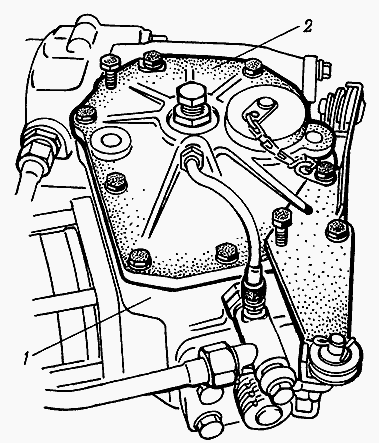
Fig. 2.3.3. Heqja e kapakut të drejtimit të energjisë MTZ-80
1 - ndërtesa GUR; 2 - mbulesa e strehimit të drejtimit të energjisë
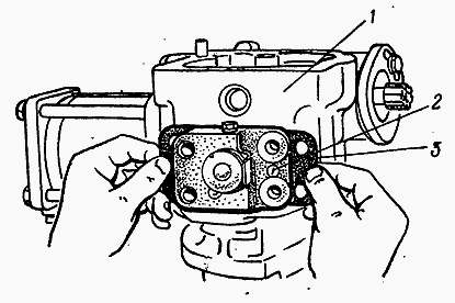
Fig. 2.3.5. Rregullimi i zhdoganimit në angazhimin e sektorit të krimbave duke instaluar gaskets
1 - ndërtesa GUR; 2 - sensori i kyçjes diferenciale; 3 - vendosja e rregullimit
Rrotullimi i vështirë i traktorit tregon mungesën e lëngut të punës në rezervuar, një rënie të furnizimit të tij, një shkelje të rregullimit të valvulës së sigurisë, veshin ose shkatërrimin e unazave të vulosjes së cilindrit të energjisë.
inspektim gjendja teknike sistemi hidraulik MTZ-80 kontrolli i rrotullimit është të përcaktojë shkallën e rrjedhës, presionin e zhvilluar nga pompa, rrjedhjet e naftës në distributori dhe cilindrin e energjisë, në rregullimin e valvulës së sigurisë. Të gjitha matjet e nevojshme kryhen pa hequr nga traktori agregatet e sistemit të kontrollit hidraulik të drejtimit, duke përdorur pajisjen KI-5473 (matës i boshtit elektrik).
Parametrat e sistemit të kontrollit hidraulik të drejtimit maten nga pajisja në një frekuencë nominale të rrotullimit të boshtit dizel, një presion mbrapa prej 5.0 MPa sipas matës së presionit të pajisjes dhe temperaturës së lëngut të punës 50-60 ° C. Leximet e shpejtësisë së rrjedhës së pajisjes shumëzohen më pas me një faktor korrigjimi prej 0.7.
Kur kontrolloni furnizimin e lëngut të punës në drejtuesin e rrymës MTZ-80 (Fig. 2.3.6), tubi i shkarkimit 2 është shkëputur nga kutia e valvulave të sigurisë dhe zorrë hyrëse e pajisjes 1. është e lidhur me të. Mëngja e kullimit ulet në qafë 3 nën nivelin e lëngut.
Ata fillojnë motorin me naftë, vendosin presionin në 5.0 MPa nga manometri në frekuencën nominale të rrotullimit të bosht me gunga, dhe në shkallën e pajisjes vini re rrjedhën e lëngut të punës. Nëse shkalla e ushqimit është më e ulët vlera e lejueshmezëvendësuar pompën.
Nëse shkalla e rrjedhës nuk është më e ulët se vlera e lejuar, përcaktoni gjendjen teknike të shpërndarësit sipas sasisë së rrjedhjes së vajit (Fig. 2.3.7).
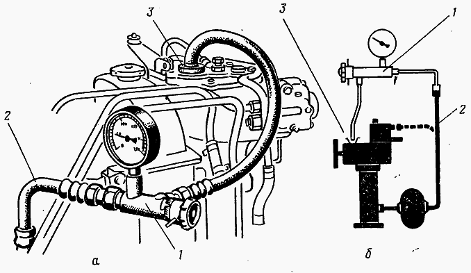
Fig. 2.3.6. Kontrollimi i gjendjes teknike të pompës së presionit të lartë të drejtimit të energjisë
A - lidhje e pajisjes; b - skema e verifikimit; 1 - pajisja KI-5473; 2 - tub shkarkimi i pompës; 3 - qafë mbushëse GUR
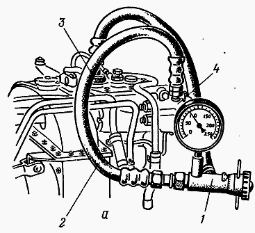
Fig. 2.3.7. Përcaktimi i rrjedhjeve të naftës në distributorin GUR MTZ-80
A - lidhje e pajisjes; b - skema e verifikimit; 1 - pajisja KI-5473; 2 - mëngë hyrëse e pajisjes; 3 - qafë mbushëse GUR; 4 - distributori i drejtimit të energjisë
Treguesit kryesorë të performancës së distributorit GUR MTZ-80 kur kontrolloni me pajisjen KI-5473
Furnizimi me naftë në P \u003d 5.0 MPa, l / min:
Vlerësimi - 2.0
- e lejueshme - 1.2
Presioni i valvulës së sigurisë, MPa:
Emri - 7.5
- e lejueshme - 7.0-8.5
Për të lidhur mëngën e hyrjes së pajisjes, priza e procesit doli së pari (priza është në majë të kutisë së valvulave të sigurisë). Zorra e kullimit është e lidhur me rezervuarin hidraulik. Ata fillojnë motorin me naftë dhe, me shpejtësinë e vlerësuar të boshtit me gunga, kthejnë timonin në të djathtë ose të majtë në të plotë.
Pasi të keni vendosur duke e kthyer dorezën e pajisjes, presioni në matës është 5.0 MPa, leximet regjistrohen në shkallën e shkallës së rrjedhës. Nëse ndryshimi në leximet e pajisjes kur kontrolloni furnizimin me lëng pune për shpërndarësin dhe kontrollimin e rrjedhjeve tejkalon 5 l / min, shpërndarësi riparohet.
Presioni i përgjigjes së valvulës së sigurisë së sistemit hidraulik të sistemit të drejtimit MTZ-80 kontrollohet nga një manometër, i cili është i dehur në vendin e prizës së procesit.
Për të kontrolluar, ata fillojnë motorin me naftë të traktorit dhe, me shpejtësinë e vlerësuar të boshtit me gunga, përdorin dorezën e pajisjes për të mbyllur plotësisht kullimin e vajit (kur rrotat kthehen në dështim). Matësi i presionit përcakton presionin aktual në të cilin aktivizohet valvula e sigurisë.
Nëse presioni i vendosur është më i ulët ose më i lartë se vlera e lejuar, valvula është rregulluar. Në këtë rast, shkulni kapakun, lëshoni butonin e kyçjes së vidhës rregulluese dhe, ndërsa mbani timonin në pozicionin ekstrem të kthesës, aq sa do të shkojë, vidhosni ose heqni vidhosin rregullues derisa të arrihet presioni nominal.
Tronditjet e mprehta gjatë kthesës së traktorit tregojnë një dobësim të shtrëngimit të arrës së rrotës së shpërndarësit hidraulik, rritjes së pastërtisë së shufrave drejtuese.
Dobësimi i shtrëngimit të arrës së bobinës shkakton dridhje (dridhje) të rrotave drejtuese të përparme, gjë që është veçanërisht karakteristike kur vozitni me shpejtësi të lartë. Në këtë rast, së pari rregulloni boshllëqet në varet e shufrave të drejtimit, dhe pastaj shtrëngoni arrën e kurorës së valvulës së rrotës me një pikëllim çift rrotullues me një çift rrotullues prej jo më shumë se 20 Nm dhe lëshojeni derisa të përputhen vrima për pin pin.
Defektet kryesore të drejtimit të energjisë MTZ-80 përfshijnë: veshin e linjave të boshtit të krimbit dhe dhëmbëve të sektorit, raft ingranazhiveshin dhe lotin e valvulës së sigurisë, veshin dhe lotin e densitetit hidraulik të pjesëve precize (spools, plungers, mëngë).
Nëse gjatë verifikimit të gjendjes teknike të njësive të sistemit hidraulik për kontrollimin e rrotullimit të traktorit, konstatohen keqfunksionime që nuk mund të eliminohen duke kryer operacione rregullimi normal, drejtimi i energjisë hiqet nga traktori dhe çmontohet për ekzaminim teknik dhe zëvendësim të pjesëve.
Sekuenca e operacioneve themelore dhe teknikat e sakta për çmontimin, montimin dhe rregullimin e drejtimit të energjisë janë treguar në Fig. 2.3.9-2.3.30.
Para se të hiqni drejtuesin e energjisë, kullojeni lëngu i punës dhe hiqni arrën e boshtit rrotullues 4. Kur montoni drejtuesin e rrymës vëmendje e veçantë kushtojini vëmendje çift rrotullimeve shtrënguese të arrave, shtrirjes korrekte të shenjave të boshtit rrotullues, sektorit dhe hekurudhave, rregullimit lëvizje vertikale boshti rrotullues.
Demontimet dhe operacionet e montimit dhe rregullimit të kryera gjatë riparimit të drejtimit të energjisë janë mjaft të ndërlikuara dhe kërkojnë përdorimin e pajisjeve të kontrollit dhe testimit pas montimit.
Drejtimi i montuar i energjisë është provuar në stolin e provës KI-4896M. Gjatë provave, kontrolli i lirë i timonit kontrollohet me një bosht vertikal të fiksuar të drejtuesit të energjisë, i cili duhet të jetë brenda 4-6 °, si dhe funksionimi i përforcuesit hidraulik nën ngarkesë me një presion hyrje të 5-6 MPa. Forca në rripin e timonit nuk duhet të kalojë 50 N.
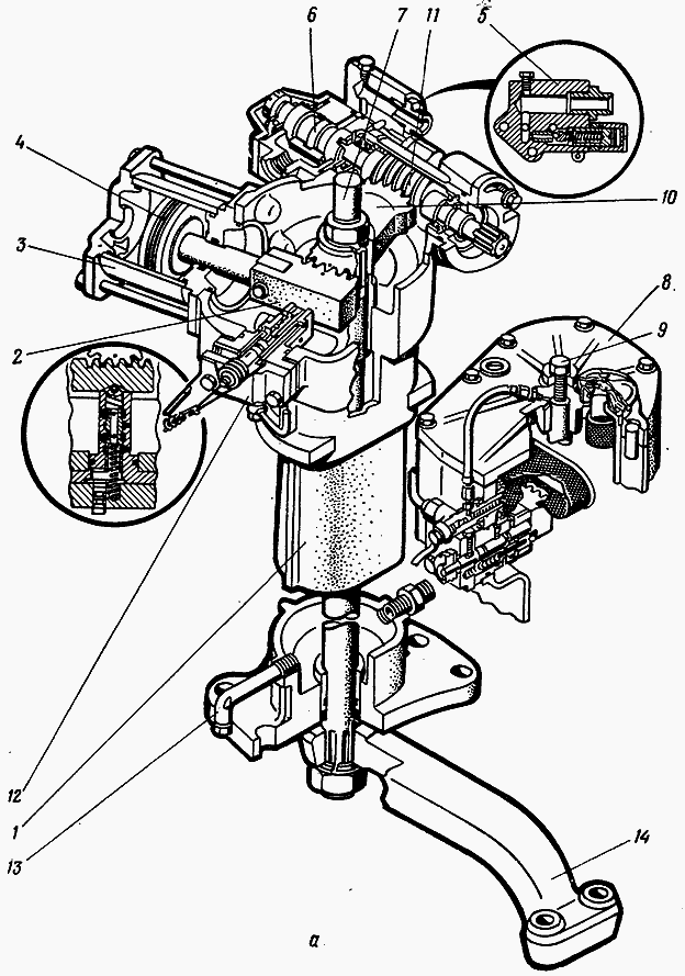
Fig. 2.3.10. Drejtues i rrymës (GUR) MTZ-80