Shkarkimi. Shkëputni telat nga bateri dhe hiqni kapakun e kaloni të sinjalit.
Largohu timon. Hiqni të dy gjysmat e kapakut të boshtit të drejtimit.
NOTE
Nëse keni nevojë të hiqni vetëm kutinë e ingranazhit drejtues, hiqni bulonat e montimit të kllapave dhe bulonën që siguron boshtin drejtues në boshtin e krimbit, atëherë rrëshqitni pak boshtin drejtues me kllapa brenda salojës dhe vendosni një qëndrim nën bosht në mënyrë që të mos varet në tela.
Në rastin e një dizajni të bifurkuar të pllakës, shtytja nga deshët transmetohet në ndërtuesin përmes blloqeve rrotulluese. Një nga avantazhet e kësaj marrëveshje është se gjatësia totale e palëve të deshve është zvogëluar në krahasim me modelin e mëngës së rrumbullakët, dhe kjo mund të jetë një faktor i rëndësishëm në disa raste. Disavantazhi është që nëse ndonjë keqpërdorim i vogël në rastin e një rrotullimi të rrumbullakët nuk është jetik, kjo mund të çojë në një pozicion të pabarabartë të blloqeve rrotulluese në strukturën e petëzuar të degëzuar, dhe është e rëndësishme që linja e shufrës të jetë saktësisht në kënde të drejta në vijën qendrore të boshtit drejtues nëse kjo shmanget.
Hiqni panelin e instrumentit dhe shkëputni prizat e ndërprerës për treguesit e drejtimit dhe fenerët nga prizat e tufës së telit.
Shkëputni telat nga prizat e ndërprerës së ndezjes dhe, pasi të keni fikur vidhat e fiksimit dhe të keni mbytur një bravë bllokimi, hiqni çelësin e ndezjes.
Pëlhurë liruese e tubit mbështetje e sipërme një bosht drejtues dhe hiqeni atë së bashku me ndërrimin e indekseve të kthesës dhe dritës së fenerëve, më parë që kanë zhbllokuar një bosht drejtues nga pajisja anti-vjedhje.
Nëse udhëzuesit nuk janë të instaluar, siç ndodh ndonjëherë me ingranazhet më të vogla drejtuese, atëherë forca e reagimit udhëzues duhet të kryhet nga kushineta ose vula cilindrash. Një tregues se efekti është një rrëshqitje e rapese, e cila jep një rritje në çift rrotullues në dispozicion me një rritje në këndin e timonit.
Vendosja e drejtimit të krimbit
i dhëmbëzuar ingranazhet gjithashtu përshtatur mirë për përdorim presione të lartatë cilat aktualisht janë të disponueshme sepse diametri i cilindrit dhe shtresa e sipërme janë relativisht të vogla dhe distancat e zvarritjes janë të vogla ose joekzistente. Drejtues cilindrash ngacmues.
Fig. 6.3. Detajet e drejtimit:
1 - ingranazh drejtues; 2 - një rrufe në fiksim të një rasti të mekanizmit drejtues në një trup; 3 - një rondele rregulluese; 4 - një rondele e sheshtë; 5 - një arrë; 6 - rondele pranverore; 7 - një rrufe në ngjitje të një maje të boshtit të një drejtimi në boshtin e një krimbi; 8 - vula e boshtit; 9 - një rrufe në ngjitje të një sealant gome në një trup; 10 - një bosht drejtues; 11 - një rrufe në ngjitje të një krahu të boshtit të një drejtimi; 12 - një krah i boshtit të një drejtimi; 13 - një timon; 14 - një arrë e fiksimit të një timoniPërdorimi i cilindrave oshilues ose disqet fikse është një zhvillim i kohëve të fundit. Ato mund të përdoren si njësi të vetme cilindrike për kontroll manual ose blloqe me dy cilindra për drejtimin manual dhe të energjisë. Ndërsa katër cilindra veprim i dyfishtë mund të trajtojë kërkesa të larta për çift rrotullues. Këto pajisje funksionojnë në një mënyrë të dyfishtë, pasi pistonët punojnë në cilindra, dhe presioni mund të aplikohet në secilën anë në krahasim me ingranazhet pingul që janë të vetme.
Hiqni kllapën 12 (Fig. 6.3) që monton boshtin drejtues. Hiqni vulën e boshtit drejtues 8.
Pasi të keni fikur një rrufe në qiell 7 të fiksimit të boshtit të një drejtimi në boshtin e një krimbi, nxirrni një bosht të një drejtuesi në sallonin e një trupi.
A.47035 tërheqës, shtypni kunjat e topit të shufrave drejtues nga vrimat në bipod.
Hiqni strehën e ingranazhit.
Në përgjithësi, çift rrotullues do të jetë më pak në këndin maksimal të drejtimit sesa maksimumi i mundshëm nga makina. Shufra të lidhur me shiritat përmes lidhjeve. Ky lloj kuti ingranazhesh përdoret nëse hapësira për dëfrim është e kufizuar ose dhoma e kokës në kokë drejtuese është e kufizuar, për shembull, në rastin e një trageti automjetduke pasur rrëshqitje në ashpërsinë. Dizajni ju lejon të lëvizni ingranazhin drejtues përpara kur ka një dhomë të arsyeshme për kokë.
Zëvendësimi i drejtimit të Bipodit
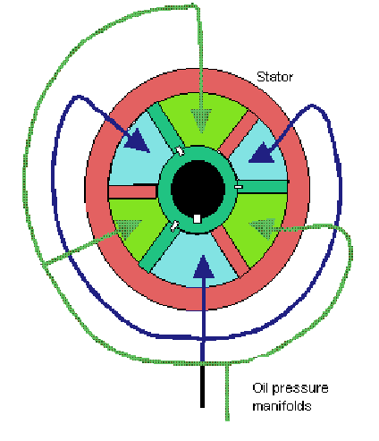
Ato përbëhen nga dy elementë. Strehim cilindrik statik me zakonisht tre brinjët e brendshme të shpatullaveqë zgjasin rrezatimisht nga brenda. Rotori është i lidhur me konturin e koncetrit dhe koncentrik; rotori ka briskë të rotorit që zgjaten rrezatimisht nga jashtë në hapësirat e formuara nga bladat e statorit.
NOTE
Kur hiqni strehën e ingranazhit drejtues, vini re numrin dhe vendosjen e rondele 3 midis anëtarit anësor dhe kutisë për t'i rivendosur ato në të njëjtin pozicion kur instaloni kthesën. Kjo është e nevojshme për të ruajtur shtrirjen e boshtit drejtues dhe boshtit të krimbit.
Fig. 6.4. Instalimi i ingranazhit drejtues në një makinë: 1 - bulonat e fiksimit të një rasti të mekanizmit drejtues në një trup; 2 - një rrufe në ngjitje të boshtit të një drejtimi në një bosht të një krimbi; 3 - bulonat e fiksimit të një krahu të boshtit të një drejtimi në një trup; 4 - një mëngë plastike; 5 - një krah i fiksimit të boshtit të një drejtimi; 6 - rregullimi i rondeleve për të siguruar shtrirjen e boshtit të krimbit dhe boshtit drejtues
Hapësirat e formuara midis fenomeneve të statorit dhe rotorit përdoren aq të larta dhe presion i ulët. Ajo ka një rrugë të gjatë për të vulosur vaj. Kjo është një makinë me çift rrotullues të vazhdueshëm në të gjitha këndet e drejtimit në krahasim me sistemin e kutisë, në të cilën, falë efektit të rrëshqitjes Rapson, çift rrotullimi në dispozicion rritet me rritjen e drejtimit.
Nëse kërkohet tepricë 100%, përdoren dy tehe rrotulluese në thelbin rrotullues. Të gjitha blades janë gize me grafit sferoidal, të montuar në një rotor prej gize dhe statori duke përdorur kunjat e çelikut me forcë të lartë dhe vidhat e mbulesës. Forca e rotorit mbështetet nga çelësat e instaluar në të gjithë gjatësinë e tehut rrotullues. Shiritat e mbylljes së çelikut janë instaluar përgjatë sipërfaqeve të punës të mbështetur nga gome sintetike në grooves përgjatë sipërfaqeve të punës, të cilat janë të ngarkuara në mënyrë elastike për të ruajtur kontaktin me sipërfaqet e çiftëzimit në mënyrë që të mbajnë presionin hidraulik.
Instalimi i ingranazheve drejtuese shpenzojnë në rendin e kundërt të heqjes. Në këtë rast, para se të shtrëngoni përfundimisht bulonat 1 dhe 3 (Fig. 6.4) duke lidhur fiksimin e kthesës së mekanizmit të drejtimit dhe kllapa të boshtit drejtues, vendosni përkohësisht timonin në bosht, rrotulloni boshtin dy ose tre herë majtas dhe djathtas. Në këtë rast, boshti dhe pjesët e tjera marrin pozicioni i saktë (vetë-instaluar) falë vrimave ovale në kavilje dhe në kllapa.
Dhomat lidhen në mënyrë alternative me thithjen dhe shpërndarjen nga pompa hidraulike, në mënyrë që ato të mund të përdoren për të krijuar çift rrotullues drejtues. Meqenëse shpërndarja e rezervuarëve të presionit është e ekuilibruar rreth marzës së drejtimit, vetëm çift rrotullues i pastër transmetohet në diferencë dhe asnjë ngarkesë anësore nuk mbivendoset nga ingranazhi.
Sot përdoren dy lloje kryesore të rrotave drejtuese me tehe rrotulluese. Në njërën prej tyre, statori i tij është montuar në mënyrë të sigurt në kuvertën e sheshtë drejtuese, dhe mbulesa e strehës dhe mbulesa e statorit janë të pajisura me kushineta të përshtatshme për të lejuar pajisjen të veprojë si një mbështetës i kombinuar i timonit dhe mbështetësja e rondës.
NOTE
Ju mund të montoni veçmas boshtin drejtues me një copë litari, kllapa, ndërprerës ndezës, ndërprerësin e treguesit të drejtimit dhe fenerin, timonin dhe instaloni këtë njësi në makinë.
Dismontimi dhe montimi i mjeteve drejtuese
Çmontimin. Kullojeni vajin nga banesa e drejtuesit. Mbërtheni kambanë në kllapën A.74076 / R me mbështetjen A.74076 / 1.
Këmbimi i unazës së drejtimit të timonit merr peshën e mekanizmit drejtues të rrotës së kthyeshme dhe timonit dhe shufrës. 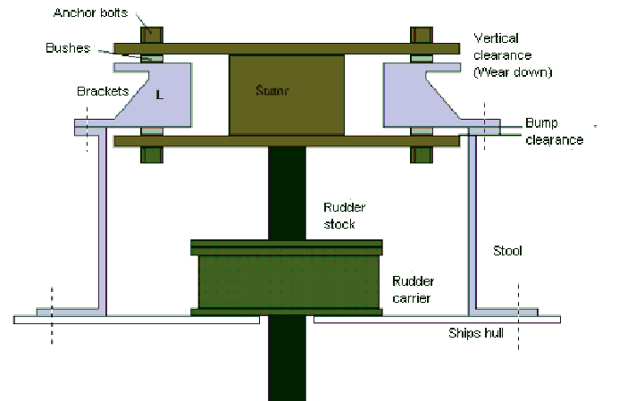
Rrotullimi i statatorit parandalohet nga dy kllapa spirancë dhe dy bulona spirancë. Kllapat e ankorimit janë ngjitur mirë në jashtëqitje, dhe pastrimi vertikal midis pjesës së brendshme të fllanxheve të statorit dhe pjesëve të sipërme dhe të poshtme të kllapave të ankorimit lejon që timoni të lëvizë vertikalisht. Ky hendek ndryshon me secilën madhësi të instalimit rrotullues, por mund të jetë rreth 40 mm.
Fig. 6.5. Largimi i Bipodit: 1 - tërheqës A.47043; 2 - një bosht i një bipodi të një drejtimi; 3 - bipod; 4 - kllapa A.74076 / R
Fig. 6.6. Pjesë zvogëluese të mjeteve drejtuese: 1 - një rast; 2 - bipod; 3 - mbulesa e poshtme e gomës; 4 - shtrimin rregullues; 5 - unaza e jashtme e kushinetës së boshtit të krimbit; 6 - një ndarës me topa; 7 - boshti bipod; 8 - vidhos rregulluese; 9 - një pllakë rregulluese; Lavatrice me 10 bllokime; 11-boshti i krimbit; 12 - mbulesa e sipërme e kamionit; 13 - një rreshtim nënshkrimi; 14 - bipod bosht shkurre; 15 - epiploon bosht krimbi; 16 - vula e boshtit bipod
Mirëmbajtja e ingranazheve drejtuese
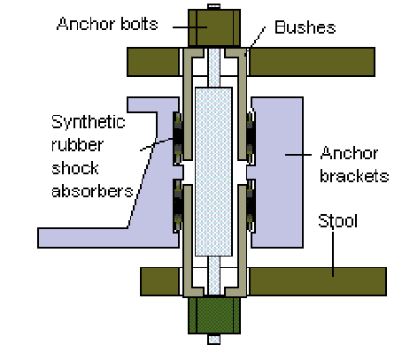
Në thelb, mbajtësi i timonit duhet të jetë në gjendje të kufizojë lëvizjet vertikale marzhi i timonit më pak se kjo shumë. Bulonat e ankorimit janë të pajisura me shkurre të posaçme në gjysmë, të formuara nga ana e jashtme për të ngarkuar para-amortizuesit e gomës sintetike, të cilat janë instaluar midis tyre dhe kllapat e ankorimit. Devijimi maksimal i amortizatorëve në ngarkesën e plotë është afërsisht 1 mm.
Këndi i punës së ingranazheve kontrollohet nga numri i blades dhe trashësia e tyre. Boshtet veprojnë si një ndalesë e timonit kur tehu i lëvizshëm kontakton tehun e fiksuar. Valvulat në hyrje të dhomave mund të jenë të mbyllura, duke shkaktuar një bllokim hidraulik. Në pajisjet e rrotullimit të shiritit, përparësia mekanike është uniforme në të gjitha këndet dhe, rrjedhimisht, çift rrotullimi është konstant.
Pasi të keni larguar një arrë fiksimi të një pirodi drejtues 3 dhe pasi të keni hequr një tërheqës të rondele pranverës А.47043, hiqni një bipod (fig. 6.5). Pasi të keni fiksuar bulonat e fiksimit, hiqni një kapak 12 (fig. 6.6) të një rasti të mekanizmit drejtues së bashku me një vidhos rregulluese 8, një pllakë rregulluese 9, një rondele bllokimi 10 dhe një arrë bllokimi. Hiqni nga manteli bipod 1 bosht 7 me mulli.
Pasi të keni fiksuar bulonat e fiksimit, hiqni një mbulesë 3 të mbajtjes së vazhdueshme të një boshti të një krimbi së bashku me rreshtimet rregulluese 4.
Kjo ingranazh përbëhet nga një tela zorrë rreth stokut të timonit, i cili përmban pistona drejtkëndëshe të rrëshqitur në ndarjet e qosheve koncentrike me stokun e timonit. Pallati zgjatet në hendekun midis cilindrit, skajet e pistonit janë ngjitur me ngjitësin, por nuk janë bashkangjitur në të, në mënyrë që lëvizja boshtore e timonit të mos mund të bartet në pistona. Ingranazhet drejtuese të këtij lloji funksionojnë me presione hidraulike deri në 41 bar dhe zakonisht janë të kufizuara nga aplikimet me fuqi të ulët.
Ingranazhe rra
Ashtu si me ingranazhet drejtuese me tehe rrotulluese, avantazhi mekanik është uniform në të gjitha këndet dhe për rrjedhojë çift rrotullimi është konstant. Izolimi i releve dhe valvulave të anashkalimit. Aktivizuesit hidraulikë janë të pajisur me valvola lehtësimi dhe anashkalimi midis çifteve shtesë të cilindrave ose dhomave të blades rrota ingranazhesh. Valvulat e sigurisë janë konfiguruar të rriten në presione mbi maksimumin normal.
Shtypni unazën e jashtme 5 të kushinetave nga kambana me boshtin e krimbit 11 dhe hiqni boshtin së bashku me kafazet mbajtëse. Zbres
Vula e boshtit të krimbit 15 dhe vula e boshtit bipod 16.
Fig. 6.7. Heqja e unazës së jashtme të kushinetës së sipërme të krimbit: 1 - mekanizëm drejtues karer; 2 - unaza e jashtme e kushinetës së sipërme të krimbit; 3 - mandrel 67.7853.9541
Valvulat e bypass-it zakonisht janë të mbyllura, por mund të hapen në një mekanizëm me dy cilindra, në mënyrë që të mund të përdoret drejtimi i urgjencës. Në një ingranazh prej katër cilindrash, një palë cilindra mund të anashkalohet, dhe çifti tjetër siguron drejtues emergjent me çift rrotullues të zvogëluar, në njësinë e kontrollit të valvulave është instaluar një pllakë udhëzuese që jep një kombinim të dështimeve dhe cilat valvula duhet të jenë të hapura ose të mbyllura për të operuar me urgjencë etj duhet të theksohet se nëse një kumarxhi ose cilindër në sistemin e katër kutive është shkatërruar, asnjëherë mos e izoloni cilindrin diagonalisht përballë njësisë së dëmtuar, pasi drejtimi nuk do të funksionojë për faktin se dy cilindrat e mbetur do të jenë ose nën të gjitha presionet ose të gjitha thithje në të njëjtën kohë.
Me mandrel 67.7853.9541, shtypni unazën e jashtme të kushinetës së sipërme (Fig. 6.7).
Asamble drejtuese shpenzoni në kllapën A.74076 / R në rendin e kundërt të çmontimit. Shtypni në unazën e jashtme të sipërme të krimbit me mandrel 67.7853.9541, duke e rivarruar grykën në dorezën e mandrelës.
Fig. 6.8. Instalimi i krimbit drejtues: 1 - mbulesë mbajtëse; 2 - shtrimin rregullues; 3 - krimb
Menaxhimi i rafteve VAZ
Eachdo cilindër ose dhomë kornizë rrotulluese është e pajisur me valvola izoluese që, kur mbyllen, mbajnë timonin, duke bllokuar vajin në dhomat. Valvulat e izolimit janë montuar gjithashtu në pompat në mënyrë që pompë të shkëputet plotësisht nga qarku dhe të hiqet për servisim ndërsa drejtimi vazhdon me pompën tjetër.
Bazat e sistemit operativ
Në rastin e ingranazheve me pompa të shpejtësisë së ndryshueshme, për të qenë në gjendje të aktivizoni shpejt njësinë e gatishmërisë, mekanizmat e goditjes së pompës lidhen vazhdimisht së bashku dhe të dy pompat mbesin të hapura për qarkun hidraulik. Kështu, ju duhet vetëm të filloni motorin për ngritësin në mënyrë që pompa të funksionojë. Të dy pompat zakonisht përdoren në ujërat e kufizuar të lundrimit. Si pompë zhvendosjeje e ndryshueshme, mund të funksionojë si motor, nëse vaji i presionit aplikohet në njërën anë gjatë goditjes së tij, është e nevojshme të parandaloni bluarjen e erës ose rrotullimin e pompës që qëndron në ngritës.
Fig. 6.9. Kontrolli i momentit të fërkimit të një krimbi nga një dinamometër: 1 - një krimb; 2 - kreu A.95697 / 5; 3-dinamometër 02.7812.9501; 4 - kllapa qëndrimi për riparimin e strehës së ingranazhit; 5 - rast drejtimi
Pas vendosjes së krimbit në kavilje të mekanizmit të drejtimit dhe sigurimin e kapakut të poshtëm, kontrolloni momentin e fërkimit të boshtit të krimbit me një dinamometër 02.7812.9501 dhe kokën A.95697 / 5 (Fig. 6.9); duhet të jetë në intervalin 19.6-49 N * cm (2-5 kgf * cm). Nëse çift rrotullues është më pak seç tregohet, zvogëloni trashësinë e shims 2 (Fig. 6.8) dhe nëse është më shumë, rritet.
Përndryshe, prodhimi i pompës së punës, në vend që të lëvizë mjetin drejtues, do të përdoret kur stenda të rrotullohet nga pompa. Një mënyrë për të parandaluar këtë është të përdorni një mekanizëm fiks kutie të përqendruar me boshtin e makinës së pompës. Mburojat që mund të përfshijnë këtë kthesë transportohen në tufën e makinës. Kur pompa është në gjendje gatishmërie, qentë merren me një mekanizëm kutie dhe parandalojnë rrotullimin kur vaji në anën e furnizimit të pompës së punës është nën presion.
Pas instalimit të boshtit bipod, kontrolloni që nuk ka boshllëk dhe angazhim të rrotullës me krimbin në pozicionet e boshtit të krimbit, të kthyer në të djathtë dhe të majtë 30 ° nga pozicioni neutral i bipodit. Hiqni çdo pastrim të mundshëm në lidhje me vidhën rregulluese 2 (Fig. 6.2) dhe shtrëngoni arrën e kyçjes 3.
Pas rregullimit të pastrimit në angazhimin e rulit dhe krimbit, kontrolloni me një dinamometër momentin e fërkimit të boshtit të krimbit, i cili duhet të jetë i barabartë me 88.2-117.6 N * cm (9-12 kgf * cm) kur boshti i krimbit rrotullohet 30 ° si në të majtë dhe në të djathtë nga pozicioni i mesëm dhe duhet të ulet pa probleme në 68.6 N * cm (7 kgf * cm) kur kthehet nga një kënd prej 30 ° në ndalesë.
Në këtë rast, prirja që motori të qëndrojë me pompën do të jetë gjithmonë kundër drejtimit të tij normal të rrotullimit. Sapo të fillojë pompa, rrotullimi është në drejtim të kundërt, qentë janë shkëputur dhe fluturojnë jashtë duke vepruar centrifugale kundër fllanxha e brendshme e bashkimit, të pastruar plotësisht nga shufra. Kur pompa është në gjendje gatishmërie dhe timoni kontrollohet nga presioni i ujit në drejtimin në të cilin lëviz për të shkaktuar presion mbi atë që është zakonisht anën e thithjes së pompës së punës, kjo do të bëjë që ajo të qëndrojë nën pompë për të kthyer në drejtimin normal të punës.
Në fund të montimit, kontrolloni këndet e rrotullimit të bipodit nga pozicioni neutral, i cili duhet të jetë 32 ° 10 "± 1" në të majtë dhe në të djathtë, derisa bipodi të ndalet në kokat e bulonave, derdhni 0.215 l në strehën e drejtimit vaj ingranazhesh Tad-17 Unë.
Inspektimi dhe Riparimi
Kontrolloni me kujdes për çdo shenjë të veshin, ngjitjes, zhytjeve ose gërvishtjeve në sipërfaqet e punës të rulit dhe krimbit. Zëvendësoni pjesët e veshura dhe të dëmtuara.
Kontrolloni pastrimin midis tufave dhe boshtit bipod, i cili nuk duhet të kalojë 0.10 mm. Nëse zhdoganimi është më i madh se i specifikuar, zëvendësoni tufat duke përdorur mandrel A.74105.
Në sipërfaqen e brendshme të tufave të boshtit bipod ka grooves spirale që shtrihen vetëm në njërën anë të shkurret. Kur vendosni tufat, vendosni ato në mënyrë që skajet e tyre që kanë daljen e brazdës të futen brenda vrimës së kthesës dhe daljet e brazdës vendosen përballë njëra-tjetrës. Skajet e shkurreve duhet të varrosen në vrimën e kamionit me 1.5 mm.
Lubrifikoni tufat e reja me vaj ingranazhi përpara montimit.
Pasi të keni shtypur në kavilje, përfundoni tufat me një rimarrës A.90336 në një madhësi prej 28.698-28.720 mm. Pastrimi i montimit midis boshtit bipod dhe tufave duhet të jetë ndërmjet 0,008-0,051 mm.
Kontrolloni lehtësinë e rrotullimit të rulit të boshtit bipod.
Kushinetat e krimbit dhe të rrotullave duhet të rrotullohen lirshëm, pa bllokime dhe nuk duhet të ketë vesh dhe dëmtim në sipërfaqen e unazave dhe topave.
Kontrolloni rrjedhën e ditarit mbështetës të boshtit të boshtit drejtues në lidhje me diametrin mesatar të vrimës së prirur të skajit të boshtit. Për të kontrolluar, skaji i poshtëm i boshtit është vendosur në një mandrel të veçantë, i cili është montuar në një prizëm. Kur ktheni mandarinën në prizëm, rrjedhja e ditarit të boshtit nuk duhet të kalojë 3 mm. Nëse boshti është deformuar, atëherë drejtojeni atë në një shtypje dore.
Kontrolloni pastrimin boshtor midis kokës vidhos rregulluese 8 (Fig. Bb) dhe një zakon i boshtit bipod 7. Zhdoganimi nuk duhet të kalojë 0.05 mm. Nëse është më e madhe, zëvendësoni pllakën rregulluese 9 me një pllakë më të trashë.
NOTE
Pllaka rregulluese me njëmbëdhjetë madhësi u furnizohen pjesëve rezervë, me trashësi 1.95 - 2.20 mm; rritja në secilën madhësi është 0.025 mm.
Figura 1 timoni
1 - draft lateral; 2 - bipod; 3 - fut mesatare; 4 - levë e lavjerrësit; 5 - tufa rregulluese; 6 - nyje e poshtme e topit e pezullimit të përparmë; 7 - grushti rrotullues i duhur; 8 - nyja e sipërme e topit të pezullimit të përparmë; 9 - levën e djathtë të gypit; 10 - kushineta e boshtit të sipërm të drejtimit; 11 - një krah i fiksimit të boshtit të një drejtimi; 12 - një tub i një krahu të fiksimit të një boshti të një drejtimi; 13 - boshti i sipërm i drejtimit; 14 - kllapa e krahut të lavjerrësit; 15 - boshti i krahut të lavjerrësit; 16 - një rast i mekanizmit drejtues; 17 - vula e boshtit; 18 - një bosht krimbi; 19 - bashkim kardan; 20 - countershaft Drejtues të energjisë; 21 - një shtresë e jashtme; 22 - leva e ndërrimit të fshirëseve dhe rondele të ekranit xham i përparmë dhe fenerët; 23 - levë e ndërrimit të dritës së fenerëve; 24 - Treguesit e drejtimit të ndërprerës së levës; 25 - një timon; 26 - një pllakë fiksimi para kllapa; 27 - një rrufe bashkuese e fiksimit të bashkimit universal; 28 - spar i trupit
Karakteristikat e pajisjes
Në një makinë VAZ-2105, drejtimi është i instaluar me veshje krimbi dhe kolona drejtuese e sigurisë. Boshti drejtues është i përbërë, përbëhet nga 13 kryesorët (fig. 1) dhe 20 boshte të ndërmjetëm. Boshti i sipërm 13 dhe boshti 18 i krimbit janë të ndërlidhura countershaft 20 me nyje kardan në skajet. Varet në kushinetat e gjilpërave janë strukturore integrale.
Boshti i sipërm është montuar në tubin e kllapës 11 në dy kushineta gjilpërash me tufa gome. Kushinetat në tub janë vulosur. Kllapa 11 është e fiksuar në kllapa të panelit të trupit në katër pika: nga poshtë me bulona me pllaka mbyllëse 26, nga lart - në bulona të ngjitur me arra dhe rondele.
Në rast të përplasje kokë skajet e pllakave të kyçjes deformohen dhe rrëshqasin nëpër vrimat e kllapës 11. Për shkak të mundësisë së palosjes së boshtit drejtues, timoni largohet nga zona e gjoksit të shoferit. Kjo zvogëlon gjasat dhe ashpërsinë e dëmtimit të tij.
Boshti i krimbit, në këtë lloj drejtimi, ka një gjatësi të madhe. Në pjesën e poshtme të boshtit të krimbit, si dhe në fundin e kaviljes 7 (fig. 2) të mekanizmit drejtues, shenjat bëhen në formën e fotove "B" dhe "C", nëse është kështu, ruli i boshtit bipod është instaluar në mes të krimbit. Në këtë rast, shpërndarësja e timonit duhet të jetë horizontale.

Figura 2. Seksioni i strehimit të ingranazhit drejtues
1 - boshti bipod rregullues i pllakës; 2 - një vidhë rregulluese e një boshti bipod; 3 - arrë e vidhës rregulluese; 4 - priza për mbushjen e vajit; 5 - mbulesa e mekanizmit të kaviljeve; 6 - një krimb; 7 - një rast i mekanizmit drejtues; 8 - bipod; 9 - një arrë e fiksimit të një bipodi në bosht; 10 - pirodi i fiksimit të arrave të pranverës së rondele; 11 - vula e boshtit bipod; 12 - tufa bronzi e boshtit bipod; 13 - boshti bipod; 14 - bipod bosht rul; 15 - boshti i krimbit; 16 - kushineta e topit të sipërm; 17 - kushineta me top të ulët; 18 - shtrimin rregullues; 19 - mbulesa e poshtme e kushinetës së krimbit; 20 - boshti i rulit; 21 - kushineta me gjilpërë; 22 - epiploon bosht krimbi; B, C - etiketat A - etiketat e ndeshjes
Mbulesa e ingranazhit të drejtimit është ngjitur në anën e majtë 28 të trupit të makinës nga pjesa e brendshme e ndarjes së motorit me tre bulona.
Në kaviljen 7 (figura 2) ekziston një krimb 6, i cili është i gërvishtur me një rrotull dykrenëshe 14 të boshtit bipod 13. Raporti i ingranazheve palë krimbi 16.4. Krimbi rrotullohet në kushinetat e sipërme 16 dhe ato të poshtme, topat e të cilave janë vendosur në rutinat e skajeve të krimbit. Pastrimi boshtor në kushinetat e krimbave rregullohet me zgjedhjen e copëzave 18 midis kthesës dhe mbulesës 19. Boshti bipod rrotullohet në dy tufa 12, të shtypura në kutinë e ingranazhit drejtues. Një rrotull 14 rrotullohet në skajin e sipërm të boshtit, në një kushinetë me gjilpërë, dhe një bifod 8 është vendosur në skajin e poshtëm të boshtit që ka shirita të rahatuar dhe fiksuar me një arrë 9. Dy zgavra të dyfishta bëhen në lëmshin e pjerrët të bipodit, dhe dy protruse të dyfishta bëhen në bosht. Prandaj, bipodi mund të instalohet në bosht në vetëm një pozicion.
Angazhimi i rrotullës me krimbin rregullohet me vidhos 2. Pastërtia boshtore midis kokës së vidhos dhe gropës së boshtit eliminohet me zgjedhjen e pllakave rregulluese 1.
Drejtimi i drejtimit përfshin tre fut - mesi 3 (figura 1) dhe dy ekstreme 1, si dhe bipodi 2, swingarm 4 me kllapa 14 dhe levat rrotulluese 9 noçkë 7. Futja mesatare është bërë e tërë. Ka nyje topi në skajet për lidhje me krahun e lavjerrësit dhe biodin drejtues. Linkdo lidhje anësore përbëhet strukturalisht nga dy skaje të filetuara të lidhura me njëra-tjetrën nga një mëngë rregulluese 5. rsiftat janë të fiksuar në lidhjet duke përdorur shufra lidhëse. Rrotullimi i tufës 5 kontrollon gjatësinë e lidhjes anësore kur rregulloni gishtin e rrotave të përparme. Këshillat e shufrave ekstremë që përdorin varet, janë bashkangjitur në levën 9 të kthesave të drejtimit, në levën e lavjerrësit 4 dhe në bipodin drejtues 2.
Lidhja e topit e shufrave përbëhet nga një gisht çeliku, koka sferike e së cilës është e mbuluar nga një insert plastik konik i ndarë, i cili shtypet nga pranvera në strehim, për shkak të kësaj, krijohet një ndërhyrje në lidhjen e gishtit me futjen dhe majën e shufrës.
Kllapa 14 (shiko Figurën 1) të krahut të lavjerrësit është e fiksuar me dy bulona në anën e djathtë të trupit të makinës, përballë dollapit të ingranazhit drejtues. Në kllapa janë dy tufa plastike në të cilat boshti rrotullohet. Vula mekanike e tufave sigurohet nga vula dhe rondele.