Despre cartea: Alocație. Ediția din 2005.
Formatul cartii: fișier pdf în arhivă zip
pagini: 46
Limba: rusă
dimensiune: 7,3 mb.
descărcare: gratuit, fără limite și parole
Sistemele de combustibil ale motoarelor diesel sunt împărțite în acțiune directă și reîncărcabile. În sistemele de combustibil cu acțiune directă, combustibilul este alimentat de la pistonul pompei de combustibil presiune ridicată (ТНВД) prin conducta de combustibil la injector. Injecția sisteme de pompe cu piston de combustibil acumulator livrează combustibil la acumulator și din acumulatorul la atomizor. Sistemele de combustibil ale motoarelor diesel pot fi, de asemenea, definite ca împărțite și neparticipate.
Pompe de combustibil Înaltă presiune împărțită la multiplunger în care, pentru fiecare cilindru există un berbec și un tip de distribuție, în care una sau două service plunger toți cilindrii, ceea ce mărește funcționarea ciclică a pistoanelor și introdus în distribuitorul de combustibil.
Conform metodei de distribuire a combustibilului pompelor de dozare cilindrilor sunt împărțite în pistonul, adesea odnoplunzhernye și rotor. Pompe plunjerul de distribuție a combustibilului către cilindrii distribuie plunger valve, rotor - o supapă de distribuție.
Pompe de distribuire de piston nu numai că face mișcare înainte, pomparea de combustibil, ci, de asemenea, se rotește, distribuirea combustibilului în cilindrii. Rotativ Pompa de combustibil de distribuție pompat pistoanele construit în rotor și un rotor rotativ distribuie combustibil la cilindrii.
Prin metoda de dozare a ciclice de combustibil de control al pompelor de distribuție a pompei de livrare sunt împărțite într-un ciclu de alimentare cu cutoff reglementat, ștrangulare aspirație, schimbă cursa tijei și controlul supapei. Este de asemenea posibil să se împartă pompele de distribuție ale sistemului de acționare a pistonului: cu profil de came extern, profilul camei cu un capăt și un profil intern cam. Primele două circuite sunt utilizate în pompele cu piston, acestea din urmă în pompele de rotor.
Conform clasificării de mai sus vizualizate ND distribuție și VE pompe aparțin pompei cu piston cu un cutoff de dozare furaje. pompele ND au o unitate de piston cu profilul extern cu came, în pompe utilizate VE soclu unitate camă plunger.
Bosch fabrică distribuție de combustibil cu piston de înaltă presiune pentru motoare diesel de la începutul anilor 1960. Prima pompă de serie Bosch EP / VM au dozare strangularea aspirației în modelele ulterioare de dozare cutoff transportate. Pompă Bosch EP / VM și toate pompele model de distribuție ulterioară a pistonului EP / VA, EP / VH, EP / VE, sunt camă soclu unitate de piston.
Din 1976, Bosch a început producția în masă a modelului Bosch VE (EP / VE). În prezent, a fost proiectată și fabricată pompa de injecție Bosch VE cu control electronic. Pompe VE, Bosch-a produs în mod direct de către, sau în conformitate cu firmele japoneze de licență Zexel (Diesel Kiki) și Nippon Denso, echipate motoare diesel în prezent cele mai autoturisme și microbuze.
În URSS primă pompă distribuitor de piston, a trecut de mai mulți ani în funcțiune, a fost OHM-pompa 4, produs de Noginskie echipamente de combustibil. În 1967, industria URSS a început producția în serie a pompelor de distribuție a pistonului ND. Pompa ND-21/4, proiectat Central de Cercetare și Institutul de Proiectare de echipamente de combustibil motoarelor auto și staționare având în vedere avantajele pompa modele OHM-1P4 și 4, este o familie ND pompă de bază.
producția de serie a pompei de distribuție rotativ a fost lansat în SUA la începutul anilor 1950, Vernon Ruza, după care a fost numit si pompa «Roosa master». Pompa a avut o transmisie cu piston cu un profil intern al camă și o dozare prin aspirație pe aspirație.
În prezent, o familie de pompă fabricat de Stanadyne System Diesel, a avut anterior numele de Hartford Mashine Screw Company. Inițial a emis modele Roosa master CB și DB de pompe, apoi au fost create familia DB2 și pompele DM4. Compania dezvoltă și îmbunătățește modelele pompei de înaltă presiune cu control electronic PCF, PCL.
Sistemul de alimentare cu combustibil diesel cu comutație pompa de combustibil odnoplunzhernym cu mecanică plonjor acționat cu camă funcționează după cum urmează (Fig. 1).
Fig. 1. Diagrama schematică a sistemului de alimentare cu combustibil motor diesel cu pompă de injecție cu un singur cap:
1 - linia de combustibil presiune scăzută; 2 - draft; 3 - o pedală de distribuire a combustibilului; 4 - pompă de injecție; 5 - supapa electromagnetică; 6 - linia de combustibil de înaltă presiune; 7 - linia de combustibil a liniei de scurgere; 8 - injector; 9 - o lumanare накаливания; 10 - filtrul de combustibil; 11 - rezervor de combustibil; Pompă de carburant (utilizat pentru autostrăzi interurbane 13 - - 12 baterie, 14 - blocare „aprindere“, 15 - unitate de control timp de comutare bujia incandescentă
Combustibilul din rezervorul 11 este pompat prin conducta de combustibil de joasă presiune în filtrul de combustibil curățarea fină combustibil 10 este aspirat de la pompa de combustibil redus de presiune și este apoi dirijat în interior cavitatea carcasei pompei 4 în cazul în care comanda sub presiune de 0,2 ... 0,7 MPa. Mai mult, combustibilul curge în secțiunea de înaltă presiune a pompei și via ștecher - distribuitor în conformitate cu ordinea cilindrilor de lucru este alimentat printr-o duză de injecție a combustibilului 6 la 8, în care combustibilul de pulverizare se efectuează într-o cameră de ardere a unui motor diesel. Excesul de combustibil de la carcasa pompei de combustibil, injectorii și filtru de combustibil (în unele modele) este drenat prin conductele de combustibil 7 înapoi în rezervorul de combustibil. Răcirea și lubrifierea pompei de injecție se realizează de către combustibilul care circulă în sistem. Filtrul de combustibil fin este important pentru funcționarea normală și fără probleme a pompei de injecție și a injectorului. Deoarece pistonul, manșonul, supapa de descărcare și elementele de duze sunt piese de precizie, filtrul de combustibil trebuie să întârzie cel mai mic particule abrazive cu dimensiunea de 3 ... 5 mm. O funcție importantă a filtrului este și reținerea și sedimentarea apei conținute în combustibil. Umiditatea care intră în interiorul pompei poate duce la defectarea pompei datorită coroziunii.
Duza. Duză (Fig. 2) este alcătuit dintr-o carcasă 2, nebulizatorul 5 cu arc deplasează acul 11 și 9. distanțier acul duzei liber în interiorul canalului de ghidare al respectivului pulverizator în timp ce în același timp, asigură o etanșare sub înaltă presiune de injecție. Partea inferioară a acului are o etanșare conică. ac duză arc este presată forma corespunzătoare a suprafeței de etanșare a corpului pistolului atunci când injectorul este în poziția închis.
Suprafețele conice ale duzelor și ale corpului acului asigură contactul cu o presiune specifică ridicată și o etanșare eficientă.
Duza se deschide când forța de la presiunea pe suprafețele conice ale acului (presiunea combustibilului) depășește forța arcului duzei. Datorită faptului că, ca rezultat ridicarea acului este o creștere bruscă a forței care acționează pe ea cu suprafața mai mare pe care afecteaza de combustibil de înaltă presiune, acest lucru este însoțită de o creștere a ofertei de combustibil datorită accelerării deschiderii acului. Va rămâne deschis până când presiunea din sistem scade sub presiunea de deschidere.
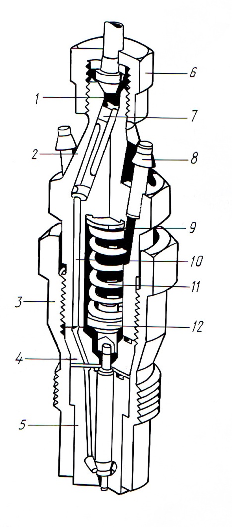
Fig. 2. Injector:
1 - canal de intrare a combustibilului; 2 - carcasa injectorului; 3 - cazul montării pulverizatorului; 4 - element intermediar; 5 - atomizor cu duză; 6 - o piuliță a unei топливопровода o presiune ridicată; 7 - filtrul; 8 - conexiune retur combustibil; 9 - șaiba de reglare; 10 - canalul de alimentare cu combustibil pentru atomizor; 11 - arc de presiune; 12 - pinul presor
deschiderea începutul presiunii (aproximativ 110 ... 140 kgf / cm2 pentru pini și duzele 150 ... 250 kgf / cm2 pentru o gated duze multi-jet) este reglat prin setarea șaibele elastice sub duze.
Presiunea de închidere este determinată de geometria duzei (raportul dintre diametrul acului și diametrul șei).
Filtre de combustibil. Filtrele de combustibil sunt proiectate pentru a curăța combustibilul din particule solide. De asemenea, protejează combustibilul de componentele care cauzează uzură în sistemul de injecție, prin urmare ele trebuie să fie suficient de capabile să colecteze un număr mare de particule ecranate și să furnizeze intervale lungi între servicii tehnice. În cazul în care filtrul se înfunda, alimentarea cu combustibil scade, iar puterea motorului scade.
Componentele de precizie ale sistemului de injecție sunt foarte sensibile la cea mai mică murdărie a combustibilului. Pentru a le proteja de uzură, sunt necesare cerințe înalte pentru a asigura o funcționare fiabilă, un consum minim de combustibil și un nivel de emisii prescris.
Cu cerințe deosebit de ridicate pentru protecția la uzură și / sau intervale de întreținere mai mari, sistemele de alimentare cu combustibil sunt livrate cu filtre grosiere și fine.
Filtrul brut de combustibil este destinat în principal pentru filtrarea particulelor mari și cel mai adesea este o rețea cu o treaptă de 300 μm.
Filtrul de combustibil fin este amplasat pe linia de combustibil din fața pompei de combustibil sau a pompei de injecție. Filtrarea are loc prin curgerea combustibilului prin elementul de filtrare 3 (fig. 3), realizat din materiale sintetice sau multistrat microfibre extrudat. Există, de asemenea, structuri alcătuite din două filtre, conectate fie în paralel pentru creșterea capacității sau în serie, care permite purificarea in trepte a combustibilului sau într-o singură unitate de conectare filtre grosiere și curățarea fină. Se folosesc tot mai multe construcții de filtrare, în care se modifică numai elementul de filtrare.
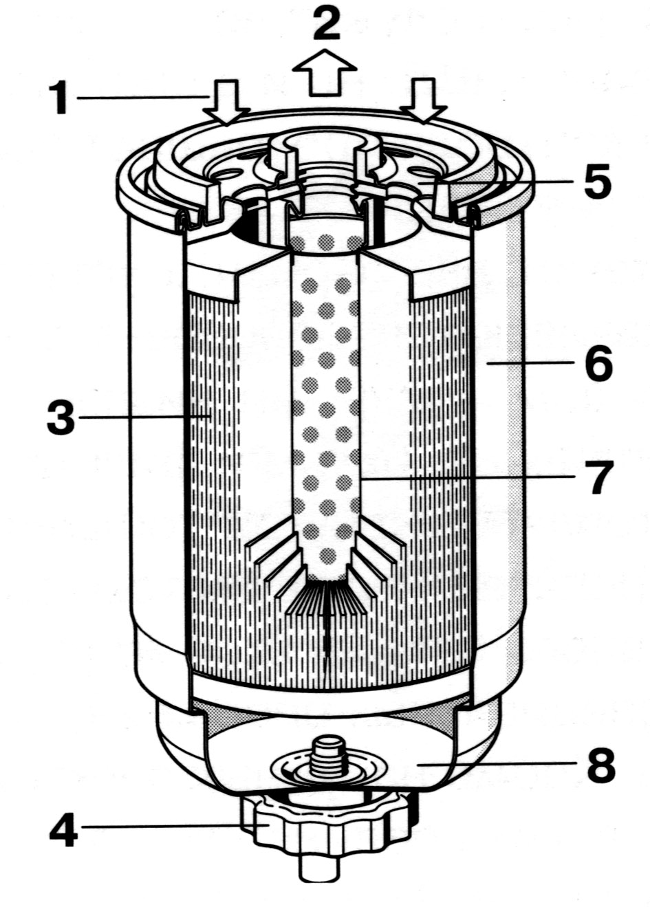
Fig. 3. Filtru pentru curățarea fină a combustibilului:
1 - alimentarea cu combustibil; 2 - evacuarea combustibilului rafinat; 3 - element filtrant; 4 - ștecher; 5 - acoperire; 6 - cazul; 7 - distanțier; 8 - colector de apă
Carburantul poate conține umiditate sub formă de picături de apă, sau sub formă de combustibil emulsie de apă (de exemplu, condensat care rezultă în schimbările de temperatură în rezervorul de carburant). În mod normal, apa nu trebuie să intre în sistemul de injecție a combustibilului.
Datorită diferitelor tensiuni de suprafață ale apei și combustibilului, picăturile de apă se formează pe elementele de filtrare. Ele se acumulează în 8. sump Pentru a elimina umezeala liber umiditate separat separator separator poate fi utilizat, în care picăturile de apă sunt separate de combustibil prin forța centrifugă. Controlați prezența senzorilor speciali de apă.
Pentru a preveni colmatarea porilor cristalelor elemente de filtrare din ceară formate în combustibil, în timpul funcționării de iarnă, filtre de combustibil utilizat la preîncălzirea combustibilului. In majoritatea cazurilor, preîncălzirea combustibilului prin intermediul unor elemente de încălzire electrice, lichid de răcire sau de combustibil alimentat din sistemul de scurgere invers.
Lumânări de incandescență. La motoarele diesel, combustibilul se aprinde din cauza temperaturii înalte a aerului comprimat. La pornirea motorului, în special la temperatură scăzută a aerului ambiant, temperatura din camera de ardere este insuficientă pentru o auto-aprindere sigură a combustibilului. Pentru a asigura o pornire fiabilă a motorului diesel în designul său un sistem de preîncălzire, folosind bujiei incandescente. Bujiile zona de injecție a aerului încălzit la o temperatură de 850 ... 1000 ° C, timp de 3 ... 4, care poate îmbunătăți în mod semnificativ la început și după funcționare timp de câteva minute pentru a încălzi aerul de intrare în timpul încălzirii lichidului de răcire la 75 ° C
Lumânările sunt împărțite în bolț cu o bobină încălzită și ceramică.
În bolțlumanarea este presată ușor în corpul 5 (Figura 4), asigurând o etanșare sigură a gazului. Pivotul este alcătuit dintr-o tijă rezistentă la termocoroziune 4, în interiorul căreia, într-o umplutură densificată 9, se găsește un filament spiralat din pulberea de oxid de magneziu. Acest fir este alcătuit din două rezistoare conectate în serie: o bobină de încălzire situată la capătul filamentului și o spirală de reglare. Bateria de încălzire are o rezistență practic independentă la temperatură, iar spirala de reglare are un coeficient de temperatură pozitiv. Când becul este în funcțiune, acesta este încălzit la o temperatură de 850 ° C și funcționează timp de 4 secunde până la 2 minute. în funcție de tipul de bujie și temperatura motorului. Combustibilul de alimentare este încălzit la temperatura optimă de combustie.
Durata perioadei de preîncălzire este reglată de unitatea de comandă a bujiilor incandescente, care monitorizează temperatura motorului prin senzorul de temperatură al agentului de răcire și modifică timpul de încălzire.
Lampa de control instalată pe panou informează conducătorul auto că încălzirea are loc. Lampa se stinge după terminarea încălzirii, ceea ce indică posibilitatea pornirii motorului. După pornirea motorului, în funcție de temperatura motorului, fișa de incendiu poate funcționa încă o perioadă. Acest lucru contribuie la îmbunătățirea arderii combustibilului în timp ce motorul se încălzește și reduce emisiile de substanțe toxice cu gazele de eșapament. În mod normal, încălzirea este pornită cu cheia de contact, întorcându-se la a doua poziție. Cu toate acestea, unele modele de autovehicule sunt echipate cu un sistem de preîncălzire, care se aprinde numai când ușa șoferului este deschisă.
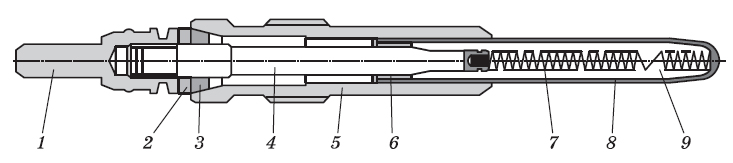
Fig. 4. Furtun incandescență:
1 - o priză de presiune electrică; 2 - șaibă izolatoare; 3 - sigiliu dublu; 4 - tija; 5 - locuințe; 6 - sigiliul reținerii; 7 - bobină de încălzire; 8 - un tub de incandescență; 9 - umplutură
Elementele principale ceramică prizele de contact sunt corpul lumanare și tija de încălzire din ceramică (Figura 5). Tija de încălzire constă dintr-un strat ceramic izolant de protecție și un element de încălzire ceramic interior care înlocuiește spirala de încălzire și ajustare a becurilor convenționale cu incandescență.
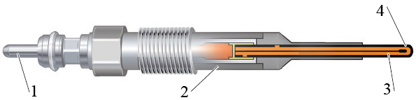
Fig. 5. Fila incandescenta ceramica:
1 - contact de legătură; 2 - corpul lumanarilor; 3 - element de încălzire ceramic; 4 - strat ceramic de protecție
Suporturi ceramice cu incandescență timp de 2 sec. ajunge la o temperatură de aproximativ 1000 ° C, ceea ce oferă aceeași pornire rapidă a motorului ca și motorul pe benzină, fără ca motoarele inerente să fie "în mișcare".
Tensiunea de încălzire are trei faze. Prima fază are o tensiune de 9,8 ... 11,5 V, la o temperatură de 1000 ° timp de 2 secunde. - Încălzire rapidă. La momente ulterioare, tensiunea de ajustare scade treptat și se află sub o tensiune de bord de rețea: Faza 2 ... 7, faza 3 ... 5 V. Pentru descărcare pini de alimentare bord bujii sunt controlate prin modulare a lățimii impulsului cu o schimbare de fază.
În plus față de aceste faze, filamentul intermediar poate fi utilizat pentru regenerarea filtrului de particule diesel. În acest caz, prizele de bujii recepționează de la unitatea de comandă a motorului un semnal de comandă pentru strălucirea intermediară. Datorită incandescenței intermediare, condițiile de combustie în procesul de regenerare sunt îmbunătățite. Datorită ușoară îmbătrânire a ceramicii, procesul de incandescență intermediară în timpul regenerării filtrului de particule nu are un efect deosebit asupra dopurilor ceramice.
Principalele avantaje ale strălucire ceramice prize lumânările metalice relative sunt cele mai bune performanțe în condiții de pornire la rece din cauza temperaturilor ridicate din filamente de gaz de eșapament mai puțin toxic anterior și ulterior datorită temperaturii filamentului mai mare și durata de viață mai lungă. Comparativ cu lumanarile din metal, lumanarile ceramice cu cerinte de tensiune mult mai mici asigura temperaturi incandescente mult mai mari.
În prezent, producătorii individuali din prizele de bujii introduc senzori de presiune pentru a corecta procesul de ardere.
Pompa de combustibil. Pompa de carburant alimentează cilindrii de înaltă presiune a unei cantități de motor diesel calibrat de combustibil la un moment dat în funcție de regimul de sarcină și de viteză, însă caracteristicile motorului depinde substanțial pompa de lucru.
Diagrama pompei de distribuție VE este prezentată în Fig. 6, și forma sa generală din Fig. 7.
Principalele blocuri funcționale ale pompei de combustibil VE reprezintă: o pompă de combustibil de joasă presiune rotativ cu palete, cu o supapă de reglare; unitate de înaltă presiune cu cap distribuitor și cuplaj de măsurare; controler automat de turație cu un sistem de pârghii și arcuri; o supapă de închidere electromagnetică care deconectează alimentarea cu combustibil; dispozitiv automat (automat) pentru schimbarea unghiului de avans al injecției de carburant.
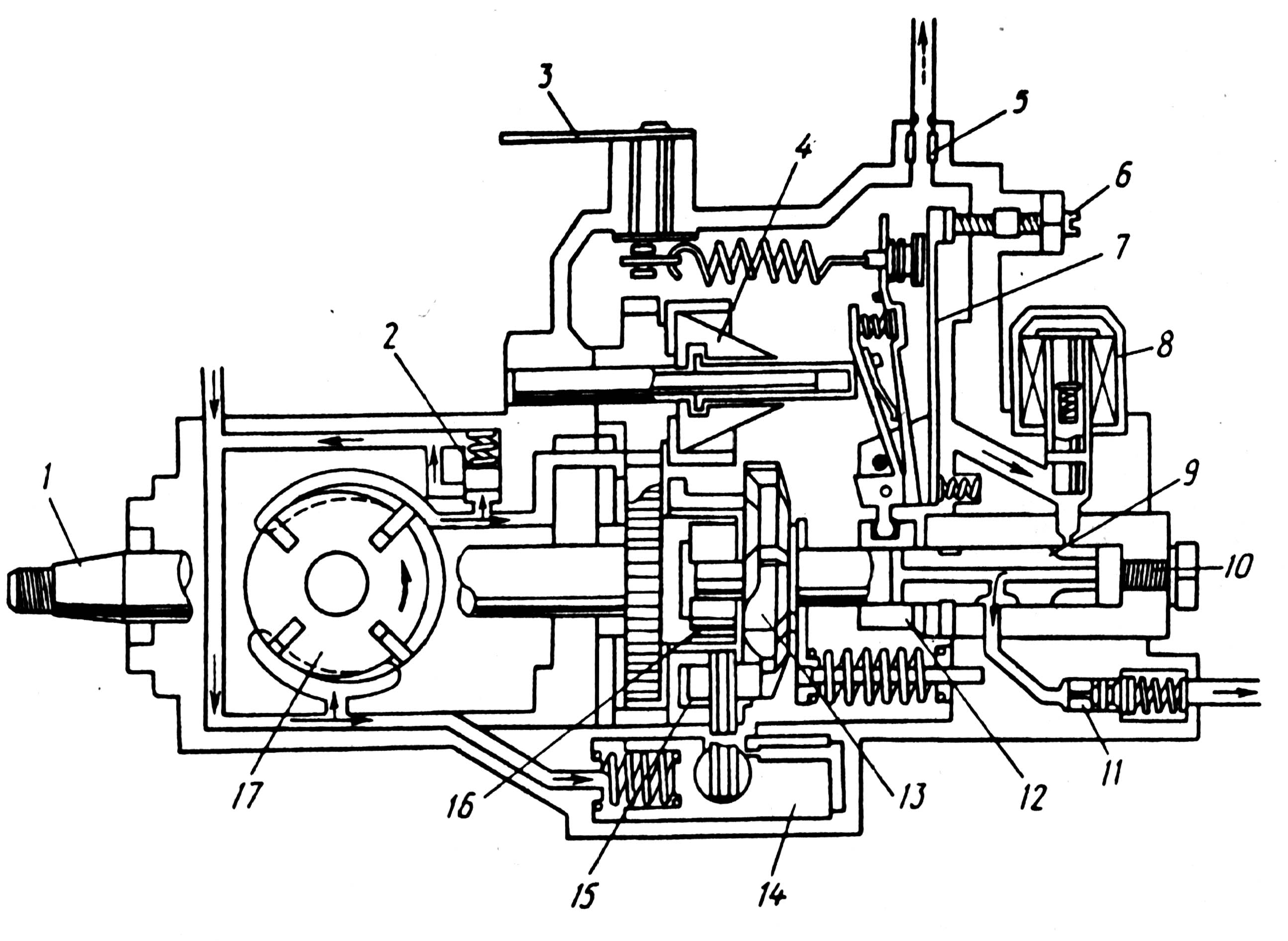
Fig. 6. Diagrama pompei de combustibil - Bosch VE:
1 - un arbore de antrenare a pompei; 2 - supapa de bypass pentru reglarea presiunii interne; 3 - pârghia de gestionare a furnizării de combustibil; 4 - sarcini ale regulatorului; 5 - jet de scurgere de combustibil; 6 - Șurub de reglare a sarcinii complete; 7 - pârghia de transfer a autorității de reglementare; 8 - supapa solenoidală pentru oprirea motorului; 9 - piston; 10 - dopul central; 11 - supapa de livrare; 12 - cuplaj de măsurare; 13 - un disc cam; 14 - avansarea automată a injecției; 15 - rola; 16 - cuplare; 17 - presiunea joasă a pompei de alimentare cu combustibil
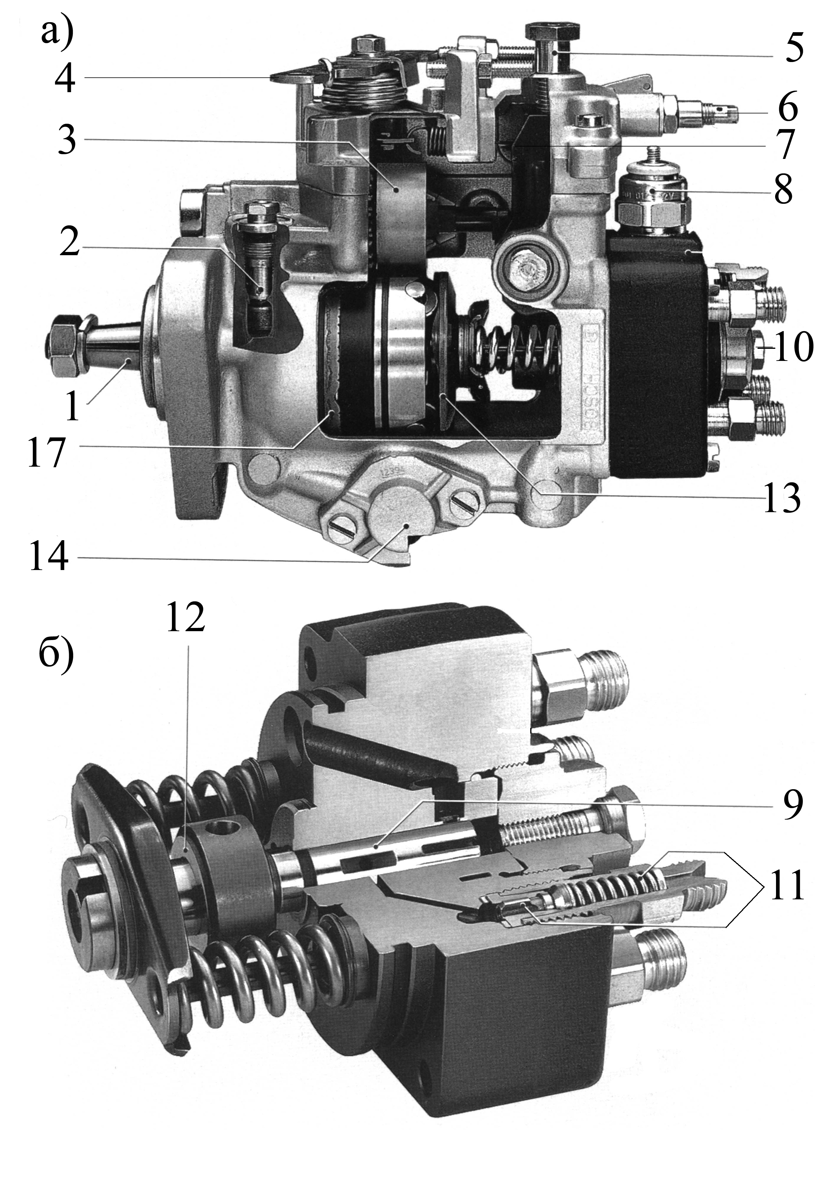
Fig. 7. Vedere generală a pompei de injecție a carburantului VE:
a - pompă de injecție; b - unitate de înaltă presiune cu cap distribuitor și cuplaj de măsurare. Pozițiile corespund pozițiilor din Fig. 6.
VE pompă de injecție distribuitor poate fi echipat cu diverse dispozitive suplimentare, cum ar fi combustibilul sau corectoare de accelerator de pornire la rece, care permit adaptarea individuală la caracteristicile pompei de injecție a unui motor diesel.
Arborele de antrenare 1, o pompă de combustibil poziționat în interiorul carcasei pompei de combustibil, un rotor montat pe axul 17 al pompei de combustibil de joasă presiune și arborele de antrenare pinion cu butonul 4. Pentru sarcini ax 1 fix instalat în inelul carcasa pompei cu role și o mașină de injecție de combustibil tijă de antrenare avansează 14. Arborele de antrenare Pompa de injecție se efectuează de la arborele cotit al motorului diesel, transmisia trenului sau centura. La motoarele în patru timpi ale vitezei arborelui pompei de injecție este jumătate din turația motorului și funcționarea pompei de injecție distribuitorului se realizează astfel încât mișcarea de translație a pistonului este sincronizat cu mișcarea pistoanelor în cilindrii unui motor diesel, iar rotațională asigură distribuția carburantului la cilindrii. Mișcarea progresivă este asigurată de dispozitivul de spălare cu came și de rotație - prin arborele pompei de carburant.
Controlul automat al frecvenței vrascheniyavklyuchaet unei greutăți centrifugale 4 care prin cuplarea regulatorului și sistemul de pârghii acționează asupra bucșei de dozare 12, modificând astfel, cantitatea de alimentare cu combustibil, în funcție de condițiile de viteză și de sarcină ale motorului diesel. Carcasa pompei este închis în partea de sus, care este instalat în axa levierului de comandă asociat cu pedala de accelerație.
Momentul de injecție de combustibil este un dispozitiv hidraulic automat a cărui funcționare este determinată de presiunea carburantului în cavitatea interioară a pompei de injecție, presiunea scăzută creată de pompa de combustibil cu un wastegate de reglare 2.
Pompă de combustibil de joasă presiune Se află în carcasa pompei pe arborele de antrenare și servește pentru a lua combustibil din rezervor și le furnizează în cavitatea interioară a carcasei pompei. Diagrama aranjamentului unei pompe de combustibil de joasă presiune cu o supapă de joasă presiune este prezentată în fig. 8.
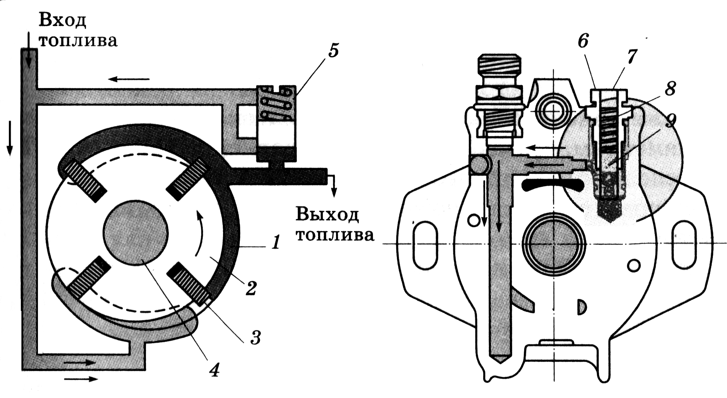
Fig. 8. Pompă de combustibil de joasă presiune și supapă de reglare:
1 - cavitate inelară; 2 - rotor; 3 - lame; 4-arbore; 5 - supapa de reglare ocolitoare; 6 - corpul supapei; 7 - un dop filetat; 8 - un izvor; 9 - pistonul
Pompa 2 constă dintr-un rotor cu patru pale 3 și inelul 1 la carcasa pompei de injecție este descentrat dispusă pe partea exterioară a rotorului. La rotirea ultimei palei prin forță de presare centrifugală pe suprafața inelului interior, creând astfel între cele două camere, din care combustibilul presurizat este furnizat prin canalul în carcasa pompei interne cavitate. În același timp, o parte a combustibilului furnizat la intrarea supapei de comandă manuală 5 și, în cazul deschiderii sale, este ocolit la intrarea pompei. Carcasa 6 a supapei de control de bypass înfășurat filetate în corpul pompei, în interiorul carcasei 9 are un piston încărcat cu un calibrat la o anumită presiune printr-un arc 8, un al doilea capăt, care se sprijină fișa 7. Dacă presiunea combustibilului este mai mare decât valoarea reglată, pistonul de supapă 9 deschide porțiunea de canal de by-pass combustibil pe partea de aspirație a pompei. Presiunea de deschidere a supapei de bypass este controlată prin modificarea poziției ștecherului 7, i. E. cantitatea de strângere preliminară a arcului 8.
Un rol important în asigurarea funcționării normale a motorului diesel joacă duză de evacuare montat în mamelonului pompa în capacul (poziția 5 din Fig. 6). Diametrul duzei de ordinul a 0,6 mm prin care combustibilul merge să se scurgă, asigură combustibil pentru a menține presiunea dorită în interior carcasa pompei cavitate. Dimensiunea duzelor este coordonată cu funcționarea supapei de by-pass.
Supapa de derivație, în combinație cu un orificiu de evacuare oferind o diferență de presiune de combustibil predeterminat în carcasa pompei dependență și de evacuare a pompei de presiune pompa de viteză redusă a arborelui. Cantitatea de combustibil furnizată de pompa de joasă presiune este de câteva ori mai mare decât cea furnizată cilindrilor diesel. presiunea combustibilului în interiorul pompei cavitate a corpului afectează poziția momentului injecției mașinii cu piston, injecție de temporizare schimbarea unghiului proporțională cu frecvența de rotație a arborelui cotit al motorului.
Elementul principal, creând o presiune mare de combustibil în pompa de înaltă presiune și distribuie combustibil la cilindrii unui motor diesel, un piston care reciprocates și o mișcare de rotație.
Principiul de funcționare a pompei este explicat în Fig.
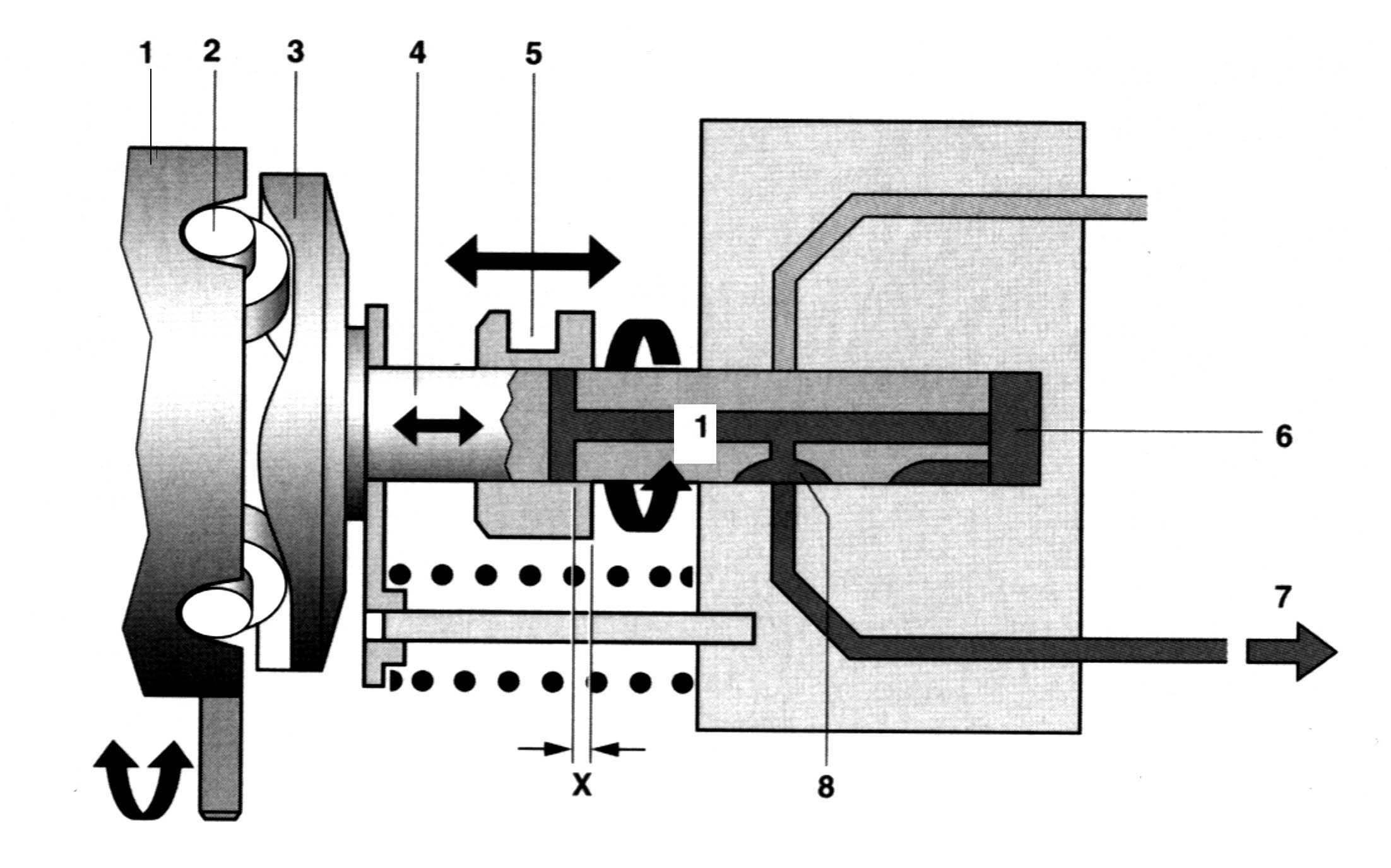
Fig. 9. Diagrama debitului combustibilului în pompa de combustibil:
1 - inel fix; 2 - rola; 3 - discul cam; 4 - piston; 5 - butucul de alimentare cu combustibil; 6 - camera; 7 - un canal de distribuire a combustibilului unui atomizor; 8 - slot de distribuție
Proeminențele came ale discului cu came 3 sunt în contact permanent cu rolele 2, montate pe axele din inelul fix 1. La rotirea plăcii cu came fiecare raid came pe rola împinge pistonul spre dreapta și a reveni la poziția sa inițială prin două arcuri unitate de pompare.
Numărul de came pe inelul cu came, ca și numărul liniei de înaltă presiune, cu supape de racorduri de livrare corespunde numărului de cilindri de motor, de obicei, patru sau șase. Ardurile de revenire ale pistonului împiedică, de asemenea, ruperea cuplării cinematice a rolei-camă a împingătorului la accelerații ridicate. Furnizarea de mișcare alternativă a pistonului, cama șaibă în formă de protuberanțe came determină, de asemenea, cursa pistonului și viteza de mișcare și, în consecință, caracteristica, presiunea și durata injecției. Toți acești parametri, la rândul lor, sunt determinați de forma camerei de ardere și caracteristicile procesului de lucru al motorului diesel dat și, prin urmare, trebuie să fie coordonate. Din acest motiv, pentru fiecare tip de profil furaj diesel se calculează Kulichkov care „suprapuse“ pe suprafața frontală a inelului cu came montat în pompă. Prin urmare, mașina de spălat camă a acestei pompe este o componentă care nu poate fi înlocuită, care corespunde individual acestui tip de motorină.
Procesele de alimentare cu combustibil. Pompă Piston creează combustibil de înaltă presiune și o distribuie la cilindrii în implementarea următoarelor etape funcționale ale combustibilului procesului: de admisie a combustibilului, cursa activă a pistonului și o injecție de carburant (injecție) cutoff de aprovizionare, procesul de închidere a supapei de evacuare și evacuarea unei linii de înaltă presiune.
Procesele de alimentare cu combustibil în capul de distribuție sunt prezentate în Fig. 10. La poziția pistonului în poziția din stânga (punctul mort) (Fig. 10a), camera de înaltă presiune 3 este combustibil primită anterior prin canalul de admisie.
Atunci când se deplasează pistonul spre dreapta (fig. 10b), combustibilul începe să se micșoreze, fanta de admisie 7 Disconnected de admisie a combustibilului 8, și de combustibil la presiunea de lucru furnizată prin canalul central al pistonului în cilindrul corespunzător dintr-un pasaj de evacuare. Supapa de presiune se deschide și combustibilul trece prin linia de înaltă presiune la injector.
livrare de combustibil se termină atunci când aranjate transversal în orificiul de alimentare cu fișă de tăiere 6 merge dincolo de cuplajul de dozare (fig. 10, c) în care ieșirile de combustibil în interiorul cavității pompei și pomparea este terminată.
La rotirea în continuare și deplasarea pistonului spre stânga (Fig. 10, d) desperechere apare fanta 2 canale de distribuție 4, orificiul de intrare aliniată cu o fantă respectiv în pistonul 8 și datorită fluxurilor de combustibil subpresiune creat în camera de presiune 3 și canalul central. Procesul de admitere și injectarea ulterioară a combustibilului are loc în timpul rotației pistonului de 90 ° într-un motor diesel cu patru cilindri, un cinci cilindri, 72 ° și 60 ° în șase cilindri.
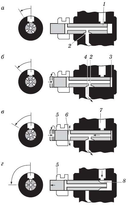
Fig. 10. Fazele de alimentare cu combustibil:
1 - piston; 2 - canelură de distribuție; 3 - camera; 4 - ieșirea; 5 - butucul de alimentare cu combustibil; 6 - gaura de control
Regulator automat de viteză. Regulatorul vitezei de rotație a pompei de combustibil considerat include un regulator mecanic cu greutăți centrifuge și un sistem de pârghii de comandă.
Schemele regulatorului cu un sistem de pârghii și poziții de lucru ale cuplajului de dozare la diferite moduri de încărcare și viteză sunt prezentate în Fig. 11 a, b, c, c.
În suportul de încărcare sunt instalate încărcături de regulator 1 (de obicei patru greutăți), care primește rotirea de pe mecanismul de acționare. mișcarea radială a mărfurilor este transformată în deplasarea axială a regulatorului ambreiajului 12, care schimbă poziția circuitului de împingere 6 și regulator 4 pârghii care se rotească în jurul axei M 2 este deplasat manșonul de dozare 9, determinând astfel cursa activă a pistonului 11.
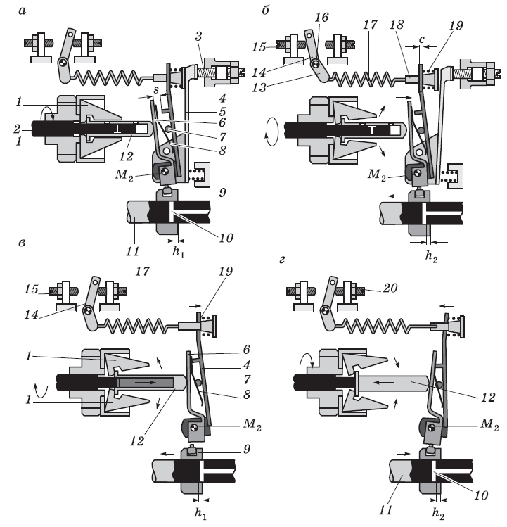
Fig. 11. Schema autorității de reglementare:
a - pornirea motorului; b - ralanti; c - modul de reducere a sarcinii; g - modul de creștere a sarcinii; 1 - bunuri; 2 axe a manșonului glisant; 3 - șurub de reglare modul maxim; 4 - pârghie de putere; 5 - pârghia de ajustare a distribuției combustibilului; 6 - maneta de împingere; 7 - accentul pus pe pârghia de putere; 8 - un arc de frunze de alimentare; 9 - cuplaj de măsurare; 10 - deschiderea de tăiere a pistonului; 11 - piston; 12 - ambreiajul glisant al regulatorului; 13 - pârghia unei tensiuni a unui arc; 14 - pârghia managementului; 15 - șurub de reglare a regimului de ralanti în modul minim; 16 - axa pârghiei de comandă; 17 - arc de funcționare al regulatorului; 18 - blocarea unui arc; 19 - un resort cu un mod minim de ralanti; 20 - șurub de reglare maximă a tijei de mers în gol
În partea superioară a pârghiei o forță minimă de arc de mers în gol 19 și între puterea și placa manetă - pornire alimentarea arc 8. Maneta de comandă 14 acționează pe butonul de operare 17, un arc, un al doilea capăt care este fixat într-o forță asupra pârghiei zăvor 18. Astfel, sistem de pârghii de poziție și, prin urmare, a manșonului de dozare este determinată de interacțiunea dintre două forțe - forța de pretensionare a regulatorului de primăvară de lucru, determină poziția pârghiei de comandă, iar forța centrifugă GRU apelați la ambreiaj.
Regulator de funcționare la pornirea motorului diesel.Înainte de pornirea motorului, arborele cotit nu a rotit și pompa de combustibil nu funcționează, sarcinile controlerului sunt în repaus la raza minimă, iar pârghia de împingere 6 (alt nume - maneta de declanșare) prin alimentarea cu pornire arc 8 deplasat spre stânga în Fig. 6.14, a, având posibilitatea de a se roti pe axa M 2. Prin urmare, capătul inferior al balamalei pârghiei asigură poziția extrema dreaptă a contorizării manșon 9 în raport cu pistonul 11, care corespunde furajului începând prin creșterea activității plonjor cursei h 1. După ce motorul pornește, sarcinile controlerului diverg și manșonul 12 se deplasează spre dreapta de valoare «S» accident vascular cerebral, depășirea rezistenței suficient de slabă arc lansator 8. Maneta 6 astfel, se rotește pe axa M 2 în sens orar, deplasarea manșonului de dozare în fluxul descendent (spre stânga în figura 11, b).
Regulatorul funcționează la turația minimă de mers în gol.În absența sarcinii și poziția manetei de comandă pe opritorul în șurubul de reglare 15, motorul trebuie să funcționeze în mod stabil la viteza minimă de ralanti în conformitate cu schema din Fig. 11, b. Reglementarea acestui mod este asigurată de un arc de ralanti 19, forța care este în echilibru cu forța centrifugă a bunurilor, și ca urmare a acestui echilibru se menține alimentarea cu combustibil, care corespunde cursului activ al plonjor 2 h. De îndată ce modul de turația motorului depășește turația minimă de mers în gol, realizat progrese „cu“ pârghie de putere în condiții de comprimare arcuri 19 sub influența creșterii sarcinilor forței centrifuge.
Funcționarea regulatorului în condiții de încărcare.În timpul funcționării unui motor diesel cu un mod de viteză regulator vserezhimnym este setat de către șofer prin efectele pedalei de accelerație de pe brațul de comandă 14. La modurile de operare de primăvară hrana de pornire 8 și un arc de ralanti 19 nu funcționează, iar lucrarea este determinată de regulatorul funcționează arcul 17. Când deformarea preliminară de rotație a pârghiei de comandă rezemat maxim șurubul de reglare modul inactiv 20 (fig. 11, a. d) în direcția creșterii modului de viteză și arc de tracțiune forța de lucru corespunzătoare acesteia Treceți forța pe pârghia 4 și apoi prin maneta 6 la regulatorul de ambreiaj 12, cauzând sarcini 1 converg. Sistemul de pârghii se rotește astfel în jurul axei M 2 în sens contrar acelor de ceasornic din fig. 11, deplasarea ambreiajului de măsurare 9 spre creșterea debitului la caracteristicile de viteză externă. Frecvența arborelui cotit al motorului și, în consecință, controlul mărfurilor va fi majorat, sarcinile forței centrifuge și rezistența ultimelor eforturile lucrătorilor din primăvară sunt, de asemenea, în creștere, iar la un moment dat vine balanța puterii și soldul pozițiilor tuturor elementelor de reglementare. În absența variației sarcinii, motorul funcționează la starea de echilibru la o viteză constantă (fără a ține seama de instabilitatea naturală a motorului cu combustie internă).
Dacă există o schimbare a sarcinii în acest mod, un controler automat va intra în operație în conformitate cu diagramele din fig. 11, c, d Când sarcina scade crește viteza de rotație, sarcinile regulatorului diverg și, învingând rezistența arcului de lucru, controlorul de ambreiaj este deplasat spre dreapta (fig. 11 c). Sistemul de pârghii este rotit în jurul axei M 2 în sensul acelor de ceasornic, deplasând ambreiajul de măsurare spre stânga, în direcția scăderii alimentării.
În Fig. 11, d arată funcționarea regulatorului în poziția pârghiei de comandă la opritorul șurubului de reglare în regim de mers în gol al modului maxim 20 și cu sarcina crescătoare. În acest caz, turația motorului diesel este redusă, sarcinile controlerului converg, forța centrifugă scade bunuri și sub forța de lucru a arcurilor ambreiajului controler se deplasează spre stânga, iar sistemul de pârghii 4 și 6 muta manșonul de măsurare spre dreapta, fluxul ascendent.
Corectorul pentru presiunea de încărcare a motorinei.Un cod automat de alarmă a fumului sau de corecție a presiunii este utilizat pentru a se potrivi consumului de combustibil al motorului diesel cu cantitatea de aer furnizată de compresor, eliminând astfel fumul de motor. Nevoia de montarea automată a dispozitivului de determinată de modificarea densității aerului în cilindrii motorului diesel supraalimentat, în funcție de modul de funcționare al turbinei de supraalimentare. Necesară mai ales pentru a lucra modul de accelerare a motorului diesel corrector, când crește cantitatea de combustibili mult mai rapid decât viteza fluxului de aer, excesul de aer scade coeficient și operarea unui motor diesel este însoțit de fumigare.
Proiectarea compensatorului de presiune instalat pe capacul superior al carcasei pompei este prezentată în fig. 12.
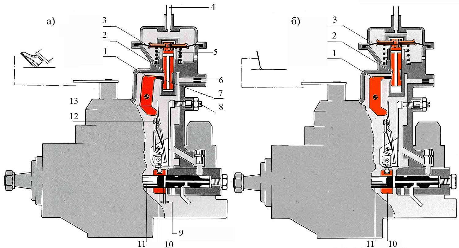
Fig. 12. Schema corectorului cu un turbocompresor:
a - poziția membranei la o presiune de creștere crescută; b - poziția membranei sub presiune de insuflare insuficientă; 1 - pârghia - accentul corectorului; 2 - rod; 3 - membrană; 4 - furnizarea vidului din galeria de admisie; 5 - un arc; 6 - jet de scurgere de combustibil: 7 - un miez; 8 - șurubul de reglare maximă a alimentării; 9 - accident vascular cerebral crescut; 10 - cuplaj de măsurare; 11 - piston; 12 - maneta de pornire; 13 - pârghie de alimentare
Cavitatea interioară este împărțită diafragma corectorului 3 în două camere - un top conectat la galeria de admisie și presurizare sub presiune și partea inferioară, care cuprinde un arc 5, care acționează asupra membranei, rezistând mișcării sale descendente. Camera de corecție inferioară este la presiune atmosferică. Membrana 3 este conectată la o tijă 2 având un con de control, care se sprijină pe impingatorui 7, o tijă de transmisie a mișcării și, prin urmare, membrana brațului egalizatorului bont 1. Tija cooperează cu brațul forței 13 a regulatorului. Corectorul funcționează după cum urmează. Dacă presiunea de supraalimentare este insuficient pentru a depăși valoarea cuplului arc este 5, diafragma 3 și tija 2 se află în poziție de repaus, așa cum se arată în Fig. 6.15, b. Prin creșterea presiunii aerului (fig. 12a), furnizat de compresor, membrana, învingând rezistența mută primăvară în jos, respectiv, prin deplasarea tijei 2 cu un con de control, prin care arborele 7 își schimbă poziția și pârghia 1 este rotit în jurul axei în sensul acelor de ceasornic sub acțiunea arcului de acționare al regulatorului. Maneta de putere 13, urmând deplasarea pârghiei de blocare-1, de asemenea, se rotește împreună cu acționare manetei 12 în raport cu axa lor comună, deplasarea manșonului de dozare în direcția de înaintare a fluxului. Astfel, cantitatea de livrare a combustibilului este în concordanță cu cantitatea de aer furnizată la cilindrii diesel, deoarece această cantitate este proporțională cu presiunea de presiune. Dacă modurile de viteză și de sarcină sunt reduse, iar reducerea arcului de supraalimentare a egalizatorului presiune deplasează membrana cu tija vertical în sus, iar mecanismul de control operează în direcția opusă celei descrise mai sus, reducând alimentarea cu combustibil la funcția de presiune de supraalimentare (Fig. 12b).
Dacă funcționarea turbocompresorului este rupt, presiunea corectorului supraalimentării, se află în poziția sa inițială pe opritorul superior (fig. 12b), oferind motorul diesel de lucru fără fumans. Debitul maxim al combustibilului pentru acest motor este reglat prin șurubul 8 montat pe capacul pompei de combustibil.
Avans automat de injectare.O aprindere anterioară mărește turația motorului când crește turația motorului. Cu o creștere a vitezei arborelui cotit, injecția începe mai devreme, care este asigurată de dispozitivul de temporizare a injecției (Figura 13).
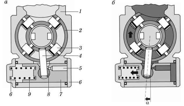
Fig. 13. Avans automat de injectare:
a - poziția de pornire; b - poziția de lucru; 1 - corpul pompei de injecție; 2 - un inel cu role; 3 - rola; 4 deget; 5 - canalul; 6 - acoperire; 7 - pistonul; 8 - sprijin; 9 - un izvor; α este unghiul de rotație al tijei
Mașina de avansare a injecției este localizată la partea inferioară a carcasei pompei 1 perpendiculară pe axa arborelui pompei de injecție. Masina cu piston 7 este închisă din ambele părți ale capacelor 6, o parte a pistonului forate trecerea 5 la presiunea de trecere a combustibilului din interiorul carcasei pompei, pe de altă parte, montată pe un arc de compresie 9. Mașina pistonului printr-o articulație 8 și o tijă (cep) 4 este conectat inelul 2 al rolei de transport 3.
Funcționarea mașinii de avansare a injecției de carburant este după cum urmează. În poziția inițială, pistonul mașinii este sub acțiunea arcului 9 (figura 13, a). Presiunea combustibilului în cavitatea interioară a carcasei pompei crește proporțional cu modul de turație a motorului este determinată și supapă reglabilă de joasă presiune (poz. 2 din Fig. 6) și funcționarea duzei la ieșirea pompei (poz. 5 din Fig. 6.9). Această presiune pe canalul 5 (Fig. 13), este transmisă la cilindrul mașinii de lucru pe o parte a pistonului, care se află sub influența forței de presiune a combustibilului la un moment dat începe să se miște spre stânga, învingând rezistența arcului 9. mișcarea axială a pistonului prin intermediul unei articulații 8 și tija 4 este transmisă inelul role care se rotește și își schimbă poziția sa în raport cu inelul cu came, astfel încât camele să afecteze rolele 3 înainte de a oferi o schimbare de fază de până la 12 ° față de unghiul de rotație al discului cu came (până la 24 ° pe YZ la manivela (fig. 13, b).
Reglarea unghiului de temporizare de injecție a unui motor diesel la pornire la rece este realizată manual de către conducătorul auto a cabinei sau automat prin intermediul unui dispozitiv de cablu, care stabilește unghiul de injecție de temporizare, în funcție de temperatura lichidului de răcire.
Modul de acționare a dispozitivului este montat pe corpul pompei de injecție, așa cum se arată în Fig. 14. Dispozitivul de pârghie este montat pe arborele 12, la celălalt capăt al cărui este descentrat dispusă știft de pivotare 3, care cooperează în rotație cu un inel 6, rolele purtătoare 7, adică, cu comanda automată a injecției de combustibil.
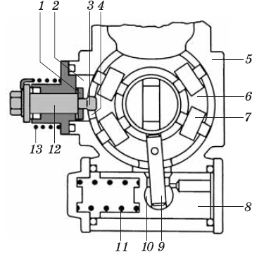
Fig. 14. Dispozitiv pentru reglarea unghiului de avans în funcție de temperatura motorului:
1 - maneta; 2 - fereastra; 3 - știft pivotant; 4 - slot longitudinal; 5 - carcasa pompei; 6 - un inel cu role; 7 - rola; 8 - pistonul; 9 - arbore rotativ; 10 - balama; 11 - arcul mașinii de avansare a injecției; 12 - axa dispozitivului; 13 - un ac de păr de primăvară
Poziția inițială a pârghiei este determinată de opritorul 3 și de arcul 4 (figura 15). În partea superioară a pârghiei dispozitivului este atașat cablul de comandă 2 de pe scaunul șoferului sau de tija mașinii de acționare 6.
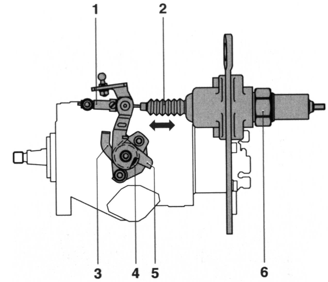
Fig. 15. Schema de acționare automată a dispozitivului pentru reglarea unghiului de avansare a injecției în funcție de temperatura motorului:
1 - draft; 2 - frânghie; 3 - accentul; 4 - un arc; 5 - maneta; 6 - corpul automat
Funcționarea dispozitivului, manuală sau automată, are loc după cum urmează. La acționarea manuală, șoferul rotește maneta 1 (Fig.14) înainte de a porni motorina cu un cablu din caroserie. Astfel, rotirea arborelui 12 și știftul 3, care prin intermediul fantei 4 inel 6 cu role 7 își schimbă poziția, rotirea în sens antiorar datorită comprimării arcului 11 și piesele de deplasare respective 8, 9 și 10, stabilind un unghi dorit avansează injecția de combustibil.
Cu unitatea automată, mașina, în interiorul căreia există un compus special care se dilată ușor, pe motorul rece asigură avansul necesar de injecție, prin reducerea volumului compoziției. Deoarece elementul de expansiune temperatura lichidului de răcire 6, în carcasă (fig. 15), mașina se oprește efectul său pe inelul cu role, prin creșterea volumului compoziției, în interiorul corpului mașinii.
Pompe de vid. spre deosebire de motoare pe benzină, unde există o supapă de accelerație și există posibilitatea de a crea un vid suficient pentru a fi utilizat în diverse scopuri, de exemplu într-un amplificator de vid sistem de frânare, într-un motor diesel datorită lipsei unei accelerații, acest lucru nu este posibil. Prin urmare, la motoarele diesel, o pompă de vid este utilizată pentru a crea un vid suficient. Una dintre variantele pompei este prezentată în Fig. 16.
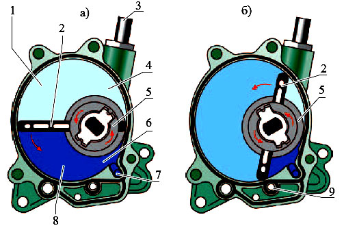
Fig. 16. Pompă de vid a motorului diesel:
a - poziția orizontală a lamei; b - poziția verticală a lamei; 1 - partea de aspirație; 2 - lama; 3 - conducte de vid; 4 - vid; 5-rotor; 6 - aer compresibil; 7 - priză de aer; 8 - partea compresiei; 9 - canalul de alimentare cu ulei
Pompa de vid conține un rotor montat excentric 5 cu o lamă de plastic 2 care se deplasează în el, care împarte cavitatea de lucru a pompei în două părți.
Când rotorul se rotește și lama se deplasează în el, volumul unei părți a cavității de lucru crește, iar volumul celeilalte părți scade.
Pe partea de aspirație, aerul este luat din sistemul de vid, care este apoi forțat prin intermediul unui canal special 7. Aerul deplasat poate fi utilizat pentru răcirea părților motorului. Printr-un canal special 9 al capului cilindrului este alimentat la pompa de ulei, care este folosit nu numai pentru lubrifiere, ci și pentru etanșarea lame în camera de lucru.
Acționarea pompei de vid este efectuată de la manivela sau arborelui cu came iar în ultimul caz pompa de vid poate fi combinată cu pompa de alimentare cu combustibil a sistemului de alimentare.
Dispozitivul bosch al pompei de injecție arată astfel. Pompa de combustibil alimentează cilindrii cu o cantitate de combustibil la o presiune ridicată, în funcție de sarcină și de viteza automobilului. Prin urmare, atunci când alegeți un motor, este necesar să acordați atenție pompei de injecție.
Blocuri Pompa avtomobilya.Osnovnye o parte esențială a pompei de combustibil de înaltă presiune este o unitate cu capul de dozare și cuplajul de dozare, regulatorul automat al vitezei cu sistem de pârghii și arcuri. De asemenea, dispozitivul include pompa bosch o pompă cu palete rotative reglare de joasa presiune supapa, supapa electromagnetică pentru închiderea orificiului de admisie, aparatul modifică unghiul de injecție de combustibil în avans. Arborele de antrenare al pompei de combustibil este amplasat în interiorul carcasei pompei de injecție. Se instalează rotorul pompei de combustibil și roata dințată acționează arborele regulatorului cu bunurile. În spatele arborelui din carcasa pompei există un inel cu role și o bară de acționare a dispozitivului de avansare a injecției de combustibil. Arborele de acționare al pompei de înaltă presiune funcționează din arborele cotit diesel, transmisia de angrenaj. Lucrarea pompei de înaltă presiune apare astfel încât mișcarea progresivă a pistonului simultan cu mișcarea pistoanelor din cilindrii motorului diesel. Șaiba asigură mișcarea de translație, iar arborele pompei de carburant este rotativ.
Pompa de injecție bosch dispozitivul pentru oprirea comenzii solenoid întrerupe alimentarea cu combustibil la pompă cu contactul decuplat.
Cel mai important element al pompei de injecție este o pompă de combustibil cu palete care aspiră combustibilul din filtrul conductei. Roata pompei este amplasată în orificiul circular al carcasei. Între glisante există întotdeauna o anumită distanță, care scade spre descărcarea pompei. Astfel, lichidul din acest volum este stins cu forța. Combustibilul este alimentat sub presiune în carcasa pompei de carburant de înaltă presiune.
Pistonul distribuitor al pompei de injecție îndeplinește funcțiile de umplere și stropire. Plunjerul constă din găuri și cavități și funcționează după cum urmează. Fanta de distribuție a pistonului este amplasată vizavi de gaura de umplere. Combustibilul se află sub presiune în spațiul liber al pistonului. Apoi pistonul se rotește și orificiul de umplere se închide din nou. Acum, discul cu came se deplasează împotriva suportului cel mai important, care transportă rulourile în același interval ca proiecțiile de pe discul discului, pentru a reduce frecarea. În plus, discul cam se deplasează de-a lungul inelului și se presează. Următoarea gaură coincide cu canalul de ieșire la duză. Combustibilul curge numai în direcția cilindrului cu compresie și aprindere.
Odată cu înăsprirea tot mai mare a normelor privind eliberarea vehiculelor de substanțe nocive-TION, pompa tradițională mi-mecanic motoarele diesel nu sunt în măsură să furnizeze dozarea necesară de combustibil de precizie și viteza de răspuns la schimbarea condițiilor de trafic. Acest lucru a condus la necesitatea unei reglementări electronice a unui număr din ce în ce mai mare de componente de combustibil motoare diesel.
Firmele Bosch, Diesel Kiki și Nippon Denso timp fabrică un număr de sisteme electronice de control, acceleratie pe baza pompei de combustibil VE, care a furnizat o îmbunătățire suplimentară a procesului de combustibil - creșterea preciziei de dozare a combustibilului în cilindrii individuali, reducerea inter-ciclu instabilitate combustie, reducând neuniformitate a motorului diesel în modul de mers în gol accident vascular cerebral. În unele sisteme instalate supapă care permite ca procesul să împartă injecția combustibilului în două faze, ceea ce reduce rigiditatea procesului de ardere rapidă care acționează.
Controlul precis nu numai că ajută la controlul emisiilor de substanțe toxice, dar oferă și o putere sporită și o funcționare mai ușoară a motorului. Unele modele au o reglare electronică a recirculației gazelor de eșapament.
În sisteme electronice aplica un pompe de combustibil de tip de distribuție, cu adăugarea dispozitivului EC controlat pentru controlul suplimentar poziția unei valve mash-up și calendarul de injectare a automatului top Liban.
Unitatea de control electronic primește semnale de la senzori set-TION cum ar fi poziția pedalei de accelerație, turația motorului, temperatura injectorului de combustibil de ridicare a acului COOL dătător și lichid, SKO-cresc vehicul, presiunii de supraalimentare și temperatura aerului de admisie și și colab.
Aceste semnale sunt procesate în unitatea de comandă electronică. Semnalul de ieșire rezultat este trimis la pompa, oferind o cantitate optimă de alimentare cu combustibil la injectoare și unghiul optim de avans prin injecție în conformitate cu condițiile de funcționare. Dacă o sarcină suplimentară este conectată (de exemplu, incluzând chayut aer conditionat), unitatea de control electronic a semnalului corespunzător sosește și sarcina suplimentară este compensată prin creșterea alimentării cu combustibil. Unitatea de comandă electronică monitorizează, de asemenea, operațiunea surse de lumină în trei etape - perioadă incandescent, funcționarea stabilă bujiei incandescente, iar perioada de după bulbi, în funcție de temperatura.
Spre deosebire de pompele mecanice, la pompele de înaltă presiune controlate electronic, creșterea turației motorului la ralanti este determinată de diafragma de comandă. Cablul acționat de o diafragmă controlează maneta frecvenței ridicate de rotație de pe pompa de combustibil. Când motorul nu funcționează, maneta se află într-o poziție cu viteză mai mare. La pornirea motorului în blocul de diafragmă se creează un vacuum, controlat de unitatea de comandă electronică printr-o supapă electromagnetică. Pe măsură ce motorul se încălzește se deschide supapa de bloc-electron-lea, in blocul IRIS-ragmennom un vid, prin care o pârghie de viteză crescută printr-o frânghie revine în poziția de mers în gol normal ing.
În majoritatea cazurilor, pentru pompele cu un singur piston de tip distribuție, ca dispozitiv executiv care reglează alimentarea ciclică. electromagnet folosit 6 (Fig. 18), cu miez rotativ, capătul căruia este conectat printr-un excentric la manșonul de dozare 5. Atunci când fluxurile de curent în înfășurarea miezului electromagnetul este rotită cu un unghi cuprins între 0 și 60 °, respectiv, deplasarea manșonului de dozare 5, prin care se produce o schimbare a cadrului hranei pentru animale.
Fig. 18. Schema desfasurata a unei pompe cu un singur piston cu control electronic:
1 - pompă de injecție; 2 - supapa solenoidală a comenzii avansării automate a injecției; 3-jet; 4 - cilindrul mașinii de avansare a injecției; 5 - dozator; 6 - dispozitivul electromagnetic al modificării distribuirii combustibilului; 7 - blocul electronic de management; 8 - senzori de temperatură, presiune de presiune, poziție de livrare a combustibilului; 9 - pedala managementului; 10 - returnarea combustibilului; - alimentarea cu combustibil a injectorului
sincronizare automată injecție este controlată printr-un ventil electromagnetic de mare viteză 2, care reglează presiunea combustibilului care acționează asupra mașinii prezent piston. Ventilul funcționează într-un mod "deschis - închis" cu impulsuri, modulând presiunea în funcție de turația motorului. Când supapa este deschisă, presiunea scade, iar unghiul de avans al injecției scade. Când supapa este închisă, presiunea crește, deplasând pistonul mașinii spre creșterea unghiului de avansare a injecției. Raportul dintre impulsuri este determinat de unitatea electronică, în funcție de modul de funcționare și de starea de temperatură a motorului. Pentru a determina momentul injectării, unul din injectori are un senzor de ridicare a acului de inducție.
Deoarece elementele de acționare care afectează organele care controlează alimentarea cu combustibil la pompa de injecție, proporțională electromagnetică aplicată, cuplul, liniar sau motoarele pas cu pas, care servesc drept contorizare acționare directă pompe de combustibil de tip distribuție.
Ca un exemplu, Fig. 19 este un dispozitiv de acționare care controlează alimentarea cu combustibil, în care electromagnetul 2 este utilizat cu miez rotativ, capătul căruia este conectat printr-un excentric la manșonul de dozare 3. Când curentul din înfășurarea miezului electromagnetul este rotită cu un unghi cuprins între 0 și 60 °, respectiv, deplasarea manșonului de dozare 3. Monitorizarea mișcării sale se efectuează cu ajutorul senzorului 1.
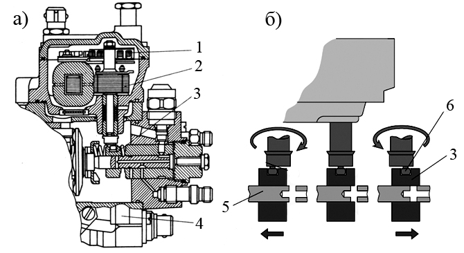
Fig. 19. Actuator electromagnetic al pompei de combustibil de tip distribuție:
1 - ecartamentul cursului unui batcher; 2 - dispozitiv de acționare (electromagnet); 3 - cuplaj de măsurare; 4 - supapa de schimbare a unui colț de la începutul injectării cu un dispozitiv electromagnetic; 5 - piston; 6 - vârful cu bile; a - secțiunea actuatorului; b - schema principiului de acțiune
Duza.Momentul injectării combustibilului este un parametru foarte important care determină funcționarea optimă a motorului diesel. Acest lucru permite specificarea unghiului zheniya opera injecție în funcție de sarcină și viteză de rotație, controlul de recirculare a gazelor de eșapament și diferitele servomotoarelor. Pentru a determina începerea injecției de carburant la pompa de injecție de combustibil de control electronic aplicat odnoplunzhernogo senzor de ridicare a acului injector cu un sistem (Fig. 20).
Corpul duzei este integrat senzor de ridicare a acului care constă din bobina de excitație 2 și excitație 3.On tijă (armătură) bobina unitatea electronică de comandă este alimentat o tensiune de referință, astfel încât curentul în circuit este menținut constant, indiferent de schimbările de temperatură. Acest curent creează un câmp magnetic în jurul bobinei. De îndată ce acul duzei se ridică, ancora 3 se schimbă câmp magnetic , determinând o schimbare a semnalului de tensiune.
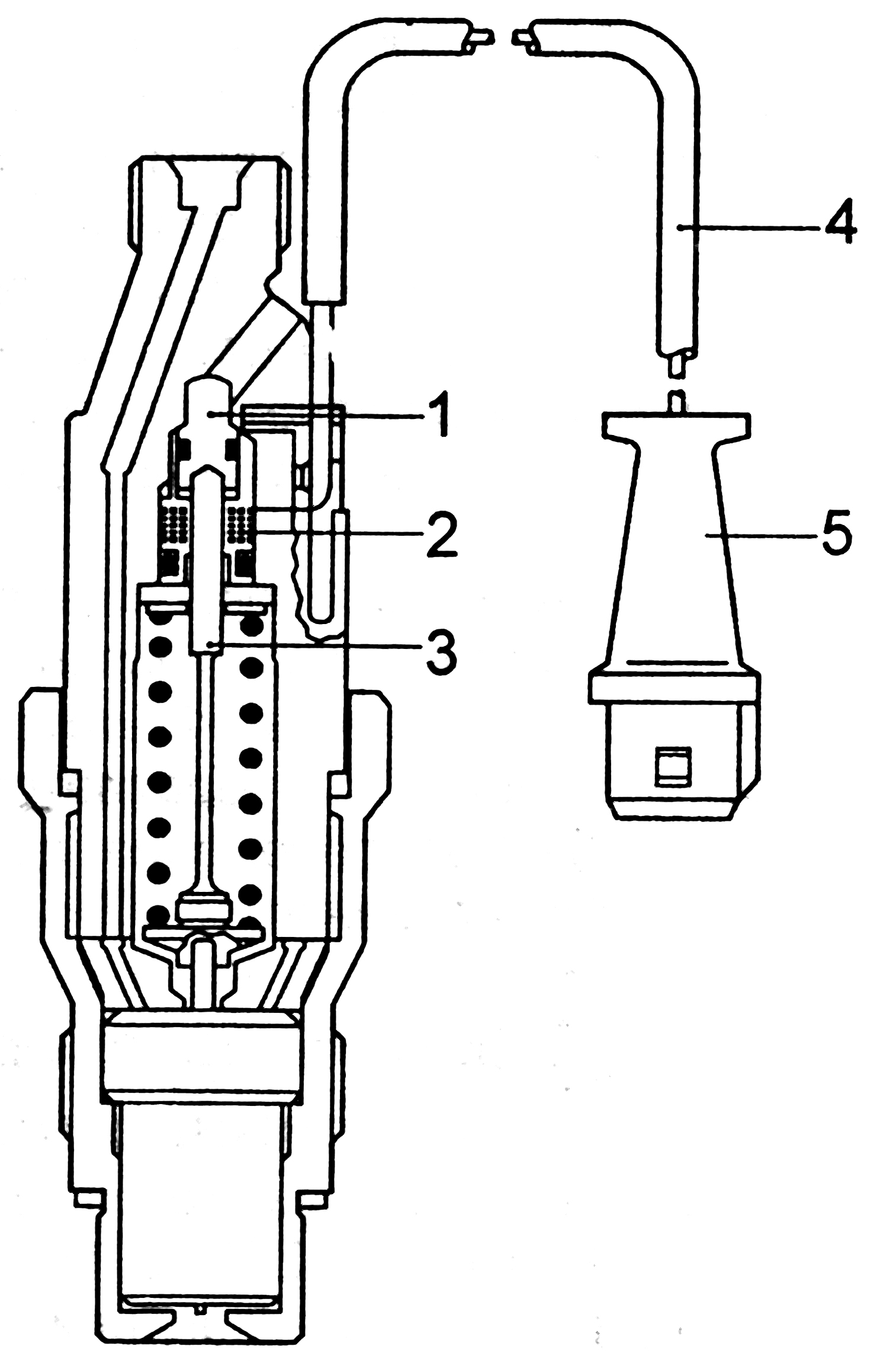
Fig. 20. Diagrama duzei cu senzori pentru ridicarea acului:
1 - șurubul de reglare; 2 - bobina de excitație; 3 - stocul; 4 fire; 5 - o priză electrică
În timpul mișcării acului, fluxul magnetic din bobină se modifică în magnitudine și induce un semnal al cărui tensiune este proporțională cu viteza acului care se mișcă, dar nu cu cantitatea de mișcare. La un anumit punct de ridicare a acului apare un impuls de vârf, care este perceput de unitatea de comandă electronică și utilizat pentru a controla momentul avansului de injectare. Acest semnal este comparat cu valorile stocate în memoria unității electronice pentru condițiile de funcționare ale motorului diesel. Unitatea de control electronic trimite un semnal de revenire la ventilul electromagnetic conectat la camera de lucru a mașinii și avansarea presiunea de injecție care acționează asupra mașinii prezent piston variază, prin care pistonul este deplasat de un arc, schimbarea unghiului de injectare de temporizare.
În locul injectorilor obișnuiți standard în sistemele electronice de injecție au apărut două duze de primăvară. Utilizarea unor astfel de injectoare poate reduce zgomotul când motorul este în funcțiune.
Duzele cu două arcuri au două arcuri, amplasate unul în altul în corpul duzei. La început, numai un singur arc acționează asupra acului, asigurând deschiderea acestuia la începutul presiunii crescute.
Cel de-al doilea arc intră astfel în contact cu bucșa de împingere, împiedicând creșterea suplimentară a acului. Cu o creștere suplimentară a presiunii, bucșa de împingere se ridică, comprimând ambele arcuri și oferind astfel o ridicare mai mare a acului. Schema unei duze cu două resorturi este prezentată în Fig. 21.
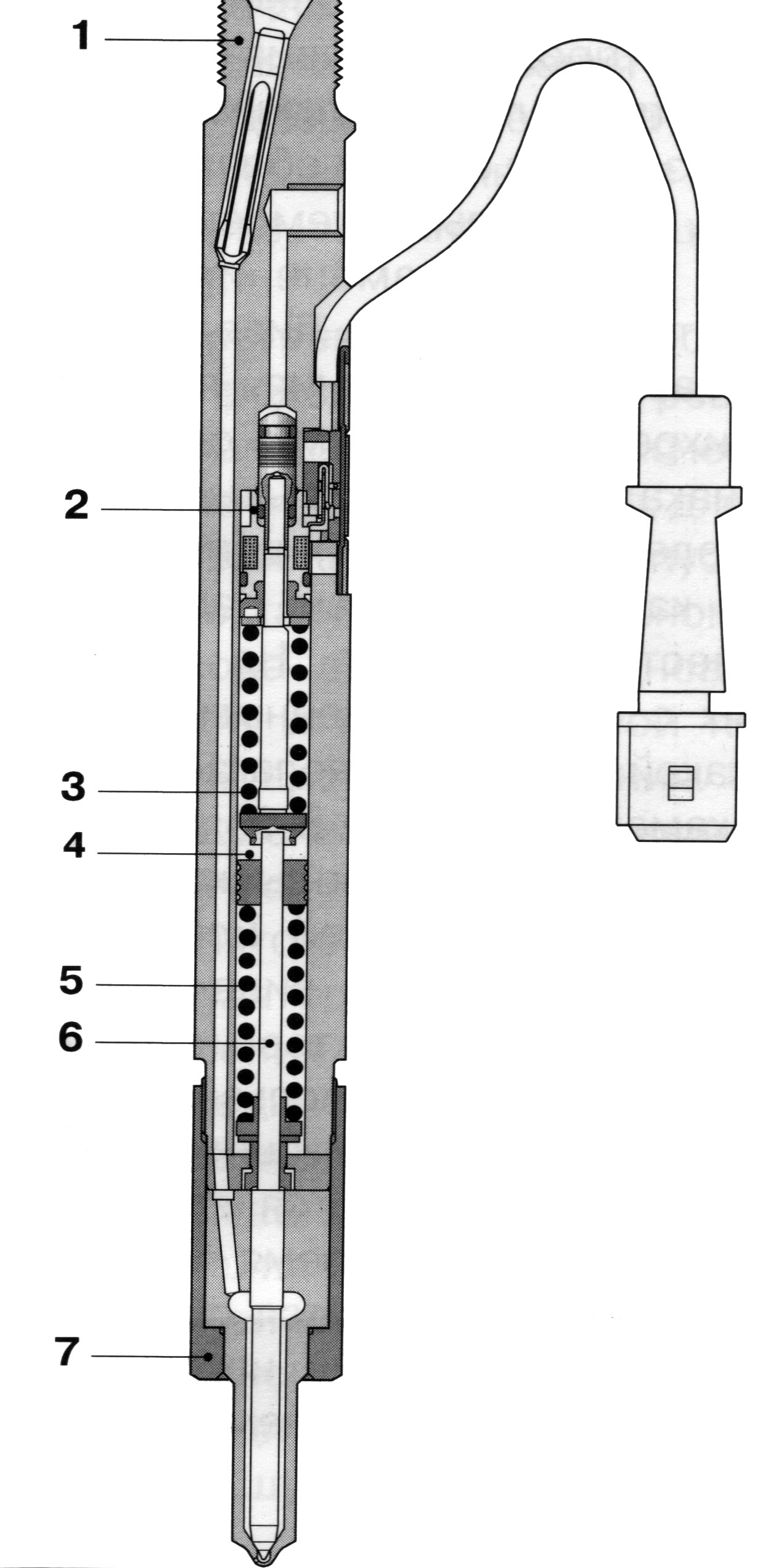
Fig. 21. Duza cu două arcuri cu senzor de ridicare a acului pentru motoarele cu injecție directă:
1 - corpul injectorului, 2 - senzorul de ridicare a acului, 3 - primul arc, 4 - elementul de ghidare, 5 - al doilea arc, 6 - pinul de presiune, 7 - piulița de montare a pulverizatorului.
Duză de lucru.La începutul procesului de injectare apare ridicarea inițială a acului, care permite doar alimentarea unei cantități mici de combustibil în camera de ardere. Cu o creștere suplimentară a presiunii de injecție, acul duzei se ridică complet și apare injecția principală de combustibil. O astfel de injecție în două etape, indicată de curba din Fig. 22, asigură un proces de ardere mai moale și duce la o reducere a zgomotului.
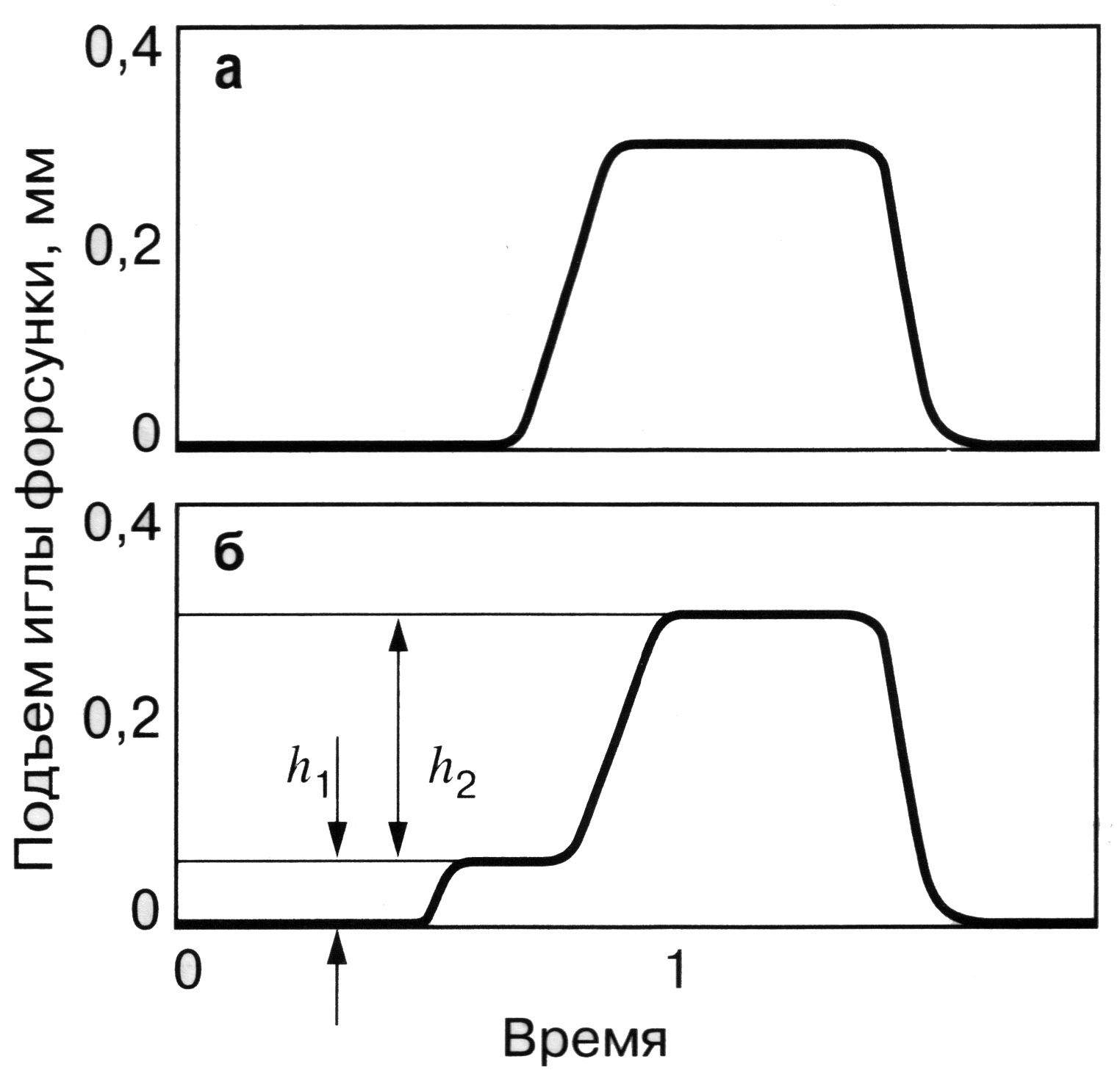
Fig. 22. Compararea caracteristicilor ridicării acului duzei:
a este un injector standard; b - duza cu două arcuri; h 1 - mutarea inițială; h 2 este mișcarea principală.
Presiunea maximă de injecție obținută prin gestionarea electronică a combustibilului pe baza pompei de combustibil VE este de 150 kgf / cm2. Cu toate acestea, resursele acestei scheme constructive pentru tensiuni într-un actuator cam cam sunt aproape epuizate. Mai avansate sunt pompa de injecție a generației următoare - VP-44.
Pompa de combustibil de înaltă presiune VP-44.
Takyenasosy a folosit în modelele de motoare diesel Opel Ecotec, Opel Astra, Audi, Ford, BMW, Daimler-Chrysler. Presiunea de injecție, dezvoltată de pompele de acest tip, atinge 1000 kgf / cm2.
Schema sistem de combustibil cu această pompă de injecție este prezentată în Fig. 23.
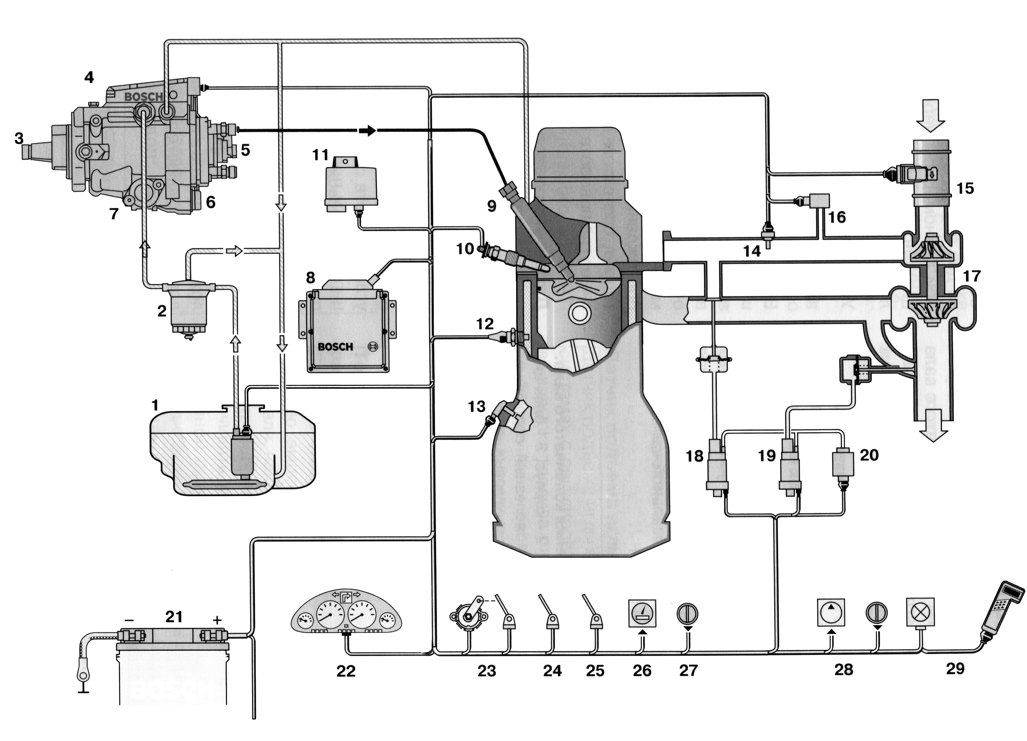
Fig. 23. Injectarea directă a unui motor diesel cu pompă de injecție VP-44:
1 - rezervor de combustibil; 2 - filtru de combustibil fin; 3 - pompă de injecție a carburantului; 4 - calculatorul pompei de combustibil; 5 - supapa electromagnetică a gestionării furnizării de combustibil; 6 - supapa solenoidală a unui colț al avansării injecției; 7 - avansarea automată a injecției; 8 - ECU de motor; 9 - duza cu senzor de ridicare a acului; 10 - dop de preîncălzire cu element de încălzire închis; Pluguri cu bujii de 11 ECU; 12 - gabaritul temperaturii unui lichid de răcire; 13 - gabaritul frecvenței de rotație a unui arbore cotit; 14 - gabaritul temperaturii aerului la admitere; 15 - masă de masă a aerului; 16 - gabaritul presiunii de presiune; 17 - turbocompresorului ; 18 - acționarea supapei sistemului рециркуляции ОГ; 19 - acționarea supapei de reglare a presiunii de presurizare; 20 - pompa de vid; 21 - bateria de stocare; 22 - panoul de bord cu indicatorul de cheltuieli de combustibil, o tahometru etc. 23 - gabaritul poziției unei pedale a unui accelerator; 24 - comutatorul de limitare (pe pedala de ambreiaj); 25 - contacte luminoase de frână; 26 - ecartamentul vitezei automobilului; 27 - unitate de control al vitezei de croazieră; 28 - compresor de aer condiționat; 29 - Ecran de diagnoză cu cabluri pentru tester de diagnosticare.
Caracteristica specială a sistemului de mai sus este o unitate de comandă combinată pentru ambele pompe de injecție și pentru alte sisteme de motoare. Unitatea de comandă este formată din două părți, cascadele finale de alimentare cu electromagneți care sunt amplasate pe corpul pompei de combustibil.
Vederea generală a pompei de injecție VP-44 este prezentată în Fig. 24.
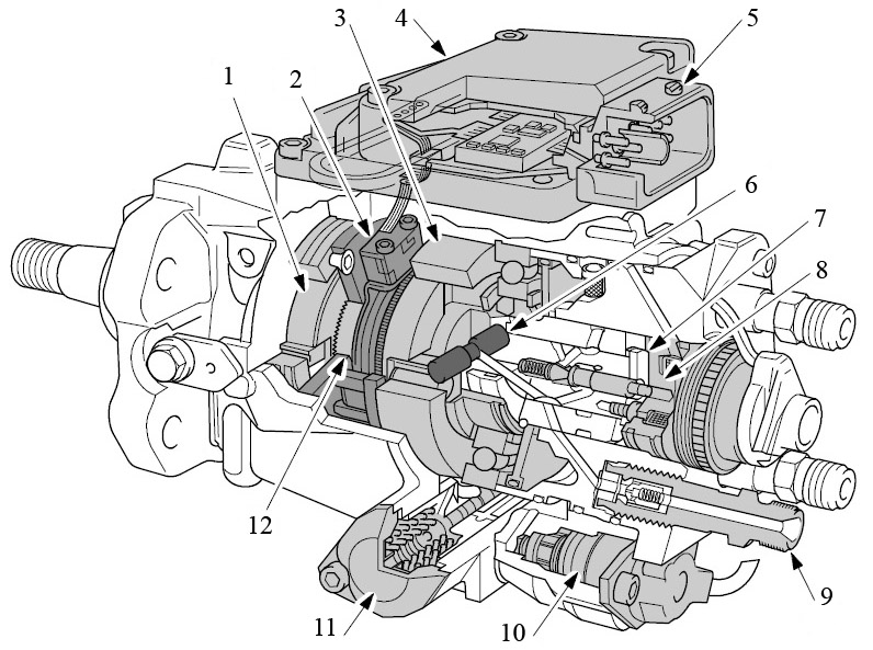
Fig. 24. Pompă de combustibil de înaltă presiune VP-44:
1 - pompă de alimentare cu combustibil; 2 - senzorul de frecvență și poziție al arborelui pompei; 3 - o mașină de spălat camă; 4 - unitate de comandă; 5 - штекерная а колодка; 6 - pistoane de injecție; 7 - distribuitor rotor; 8 - supapă solenoidală pentru controlul alimentării; 9 - supapa de livrare; 10 - supapa solenoidală pentru stabilirea momentului la care începe injecția; 11 - dispozitivul de avansare a injectării; 12 - gabaritul unui colț de rotație al unui arbore de antrenare ТНВД.
Circuit de joasă presiune. Pompa de alimentare cu combustibil 17 (Figura 25) din pompa de injecție tip glisantă VP-44 este similară cu cea discutată mai sus. Presiunea combustibilului generată de pompa de combustibil pe partea din amonte depinde de viteza roții pompei. În același timp, această presiune crește disproporționat cu creșterea vitezei. Supapa de control al presiunii 2 este situată în imediata vecinătate a pompei de alimentare cu combustibil. Valva schimbă presiunea de injecție generată de pompa de combustibil, în funcție de consumul de combustibil necesar.
Combustibilul din pompa de alimentare cu combustibil trece în secțiunea de pompare a pompei de injecție și a dispozitivului de control al injectării.
Fig. 25. Schema hidraulică a pompei de injecție VP-44:
1 - blocul de management al activității unui motor diesel; 2 - supapa de control al presiunii; 3 - pistonul supapei de reglare a presiunii; 4 - supapa de accelerație; 5 - canal de ramificație; 6 - accelerația; Unitatea de comandă a pompei de injecție a combustibilului 8 - amortizor de piston; 9 - supapă solenoidală pentru controlul alimentării; 10 - supapa de livrare; 11 - injector; 12 - supapa solenoidală pentru stabilirea momentului de la începerea injectării; 13 - distribuitor rotor; 14 - secțiune pompă de pompă de înaltă presiune cu mișcare radială a pistoanelor; 15 - ecartamentul unui colț de rotație a unui arbore de antrenare ТНВД; 16 - unitatea de control al injectării; 17 - pompă de alimentare cu combustibil.
Dacă presiunea combustibilului produsă depășește o anumită valoare, marginea torusului-tsevaya a pistonului 3 se deschide-up răspunsurile Stia dispuse radial și să le taie che fluxul de combustibil se unește cu o singură pompă-nalam la un canal de aprovizionare. Dacă presiunea combustibilului este prea mică, aceste găuri radiale sunt închise datorită predominării forțelor arcului. Pretensionarea arcului determină, prin urmare, valoarea presiunii de deschidere a supapei.
Pentru răcire pompa de transfer și scoaterea din acesta aerul Livo sus trece prin șuruburi la carcasa pompei 4 supapa de ocolire a clapetei.
Această supapă este retrasă superior Lib prin canalul de aerisire 5. Corpul supapei este încărcat cu clorhidric pruzhi-bilă, care permite vyte Katyas-combustibil numai după atingerea definită împărțită la presiunea în canal.
Dilatatorul 6 cu diametru foarte mic, conectat la linia de ramificație, este localizat în corpul supapei paralel cu orificiul principal de evacuare a combustibilului. Oferă eliminarea automată a aerului de la pompă. Toate circuitul pompei de combustibil de joasă presiune este proiectat astfel încât rezervorul de combustibil prin supapa de ștrangulare re-start curge întotdeauna coli onoruri un combustibil.
Circuit de înaltă presiune.La o presiune ridicată în buclă WMOs-DYT pompa de asamblare și distribuție și reglarea mărimii și timpului pentru a alimenta provo folosind doar membru-un singur picior - electromagnetic de înaltă presiune stem Pana.
Secțiunea de pompare a pompei de înaltă presiune cu mișcarea radială a pistoanelor creează presiunea necesară injecției de până la 1000 kgf / cm2.
Acesta este condus prin arbore și include (Figura 26):
Conectarea șaibei;
Pantofi 4 cu role 2;
Șaibă de camă 1;
Pistoanele de injecție 5;
Partea frontală (capul) arborelui distribuitorului 6.
Fig. 26. Exemple de amplasare a pistoanelor:
a - pentru patru sau șase cilindri; b - pentru șase cilindri; c pentru patru cilindri; 1 - șaiba de camă; 2 - rola; 3 - canelurile de ghidare ale arborelui de antrenare; 4 - pantoful rolei; 5 - piston de presiune; 6 - distribuitor ax; 7 - camera de înaltă presiune
Cuplul de pe arborele de antrenare este transmis prin intermediul șaibei de conectare și a racordului direct la arborele distribuitorului. caneluri de ghidare 3 servesc prin pantofii 4 și așezat în ea role de lucru 2 asigură de pompare a pistonului 5-ghidaje conform acestuia inel cu came cu profil intern 1. came Co-lichestvo pe șaibă Corespunzător există un număr de cilindri de motor.
În arborele arborelui de distribuție, pistoanele de presiune sunt amplasate radial, ceea ce a dat numele acestui tip de pompă de injecție. Pe Soare-prinderea Piston cu came camera de profil coextrudat în comun de combustibil-ban-sectorial presiune 7. În funcție de numărul de cilindri de MOTOR Tell și condițiile de aplicare există opțiuni sushchest-pompă cu două, trei sau patru piston de rapel.
Carcasa de distribuție (figura 27) constă din:
Flansa 6;
Introduceți bine în flanșa bucșei distribuitorului 3;
Situată în manșonul distribuitorului din spatele arborelui distribuitorului 2;
Ace de închidere 4 a supapei solenoidale de înaltă presiune 7;
Membrana de acumulare 10, care separă cavitatea de pompare și scurge;
Conectare la linia de înaltă presiune 16 cu supapă de evacuare 15.
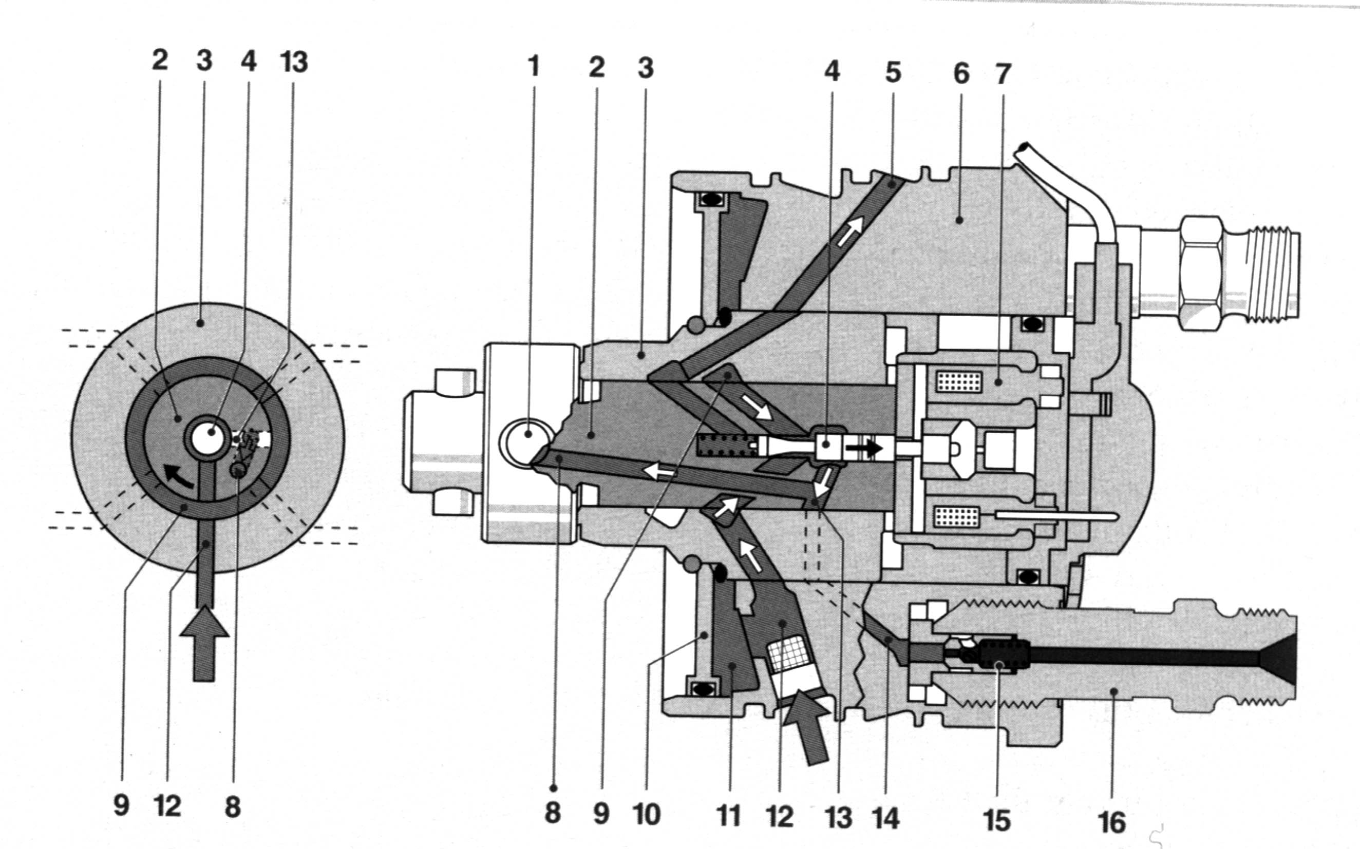
Fig. 27. Locuitor-distribuitor:
1 - piston ; 2 - distribuitor ax; 3 - fișa de distribuție; 4 - acul de blocare al supapei electromagnetice de înaltă presiune; 5 - canalul de golire a combustibilului; 6 - flanșă; 7 - o supapă solenoidală de înaltă presiune; 8-canal al camerei de înaltă presiune; 9 - canal inelar de admisie a combustibilului; 10 - membrană acumulatoare care separă cavitățile de pompare și drenare; 11 - cavitatea din spatele membranei; 12 - cameră de joasă presiune; 13 - canelură de distribuție; 14 - canalul de evacuare; 15 - supapa de livrare; 16 - conexiune la țeavă de înaltă presiune
Faza de umplere (fig. 28 a) nis came Prinderea profil radial pistoanele 1 în mișcare sunt deplasate spre exterior, spre suprafața de camă la Xai. Acul de blocare 4 este în acest caz într-o stare liberă, deschizând canalul de admisie a combustibilului. 9 prin pasajul inelar camera de jos presiune trecerea combustibilului și acul este ghidat de pompa de transfer printr-o conductă 8 al distribuitorului puțului și umple de înaltă presiune ca-măsură. Excedentul top-лива urmează prin canalul de întoarcere a prunii.
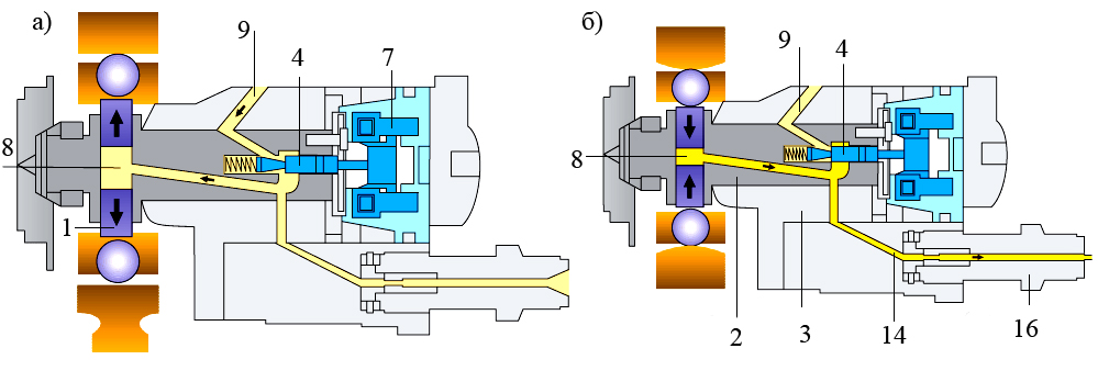
Fig. 28. Diagrama de bază a alimentării cu combustibil (pozițiile din figură corespund pozițiilor din figura 27)
În faza de evacuare (Figura 28, b) plunzhe-ry 1 cu un ac închis 4 să se deplaseze în sus spre axa camă axul distribuitorului, creșterea presiunii în camera de presiune.
Datorită acestui fapt, combustibilul sub presiune înaltă se deplasează de-a lungul canalului 8 al camerei de înaltă presiune. Apoi, combustibilul prin canelura de distribuție 13 (fig. 27), co-Thoraya în această fază se conectează arborele de distribuție-compas 2 la canalul de evacuare 14, shtu-CER 16 cu o supapă de evacuare, de înaltă presiune ma gistral iar duza intră în camera de ardere .
Dozarea combustibilului utilizând o supapă solenoidală de înaltă presiune.
O supapă solenoidală de înaltă presiune 7 este integrată în pompa de injectare de înaltă presiune pentru dozarea alimentării ciclice.
Prin electrovalva de alarmă de presiune înaltă pe care consiliile MENT-unitate de pompare la bobina electromagnetului este energizat, și armătura turn-schaet ac 4, apăsându-l pe scaunul supapei. Dacă acul este apăsat pe șa, combustibilul intră numai în canalul de ieșire de înaltă presiune 14 conectat la supapa de presiune, unde presiunea crește brusc și de la acesta la injector. Dozarea alimentării cu combustibil este determinată de intervalul dintre începerea debitului și momentul deschiderii valvei solenoidale și se numește durata de alimentare.
Durata închiderii supapei electromagnetice, determinată de unitatea de control, reglează astfel cantitatea de alimentare ciclică a combustibilului. După terminarea injecției, supapa solenoid nu este alimentat, supapa de înaltă presiune electromagnetică se deschide și PRESIUNE stabilite în circuitul este redus, oprirea alimentării cu combustibil a duzei.
Combustibilul exces, care este pompat până la punctul în care pistonul trece prin punctul superior al profilului cam, este ghidat printr-un canal special în spațiul din spatele membranei de acumulare. Săriturile de înaltă presiune, care apar în circuitul de joasă presiune, sunt amortizate de o membrană de acumulare. În plus, acest spațiu păstrează combustibilul acumulat pentru procesul de umplere înainte de injectarea ulterioară.
Pentru a opri motorul cu ajutorul unei supape electromagnetice, descărcarea de presiune ridicată este complet oprită. În consecință, nu este necesară o supapă suplimentară de oprire, cum este cazul pompei de injecție cu comandă a muchiei de reglare.
Amortizarea undelor de presiune prin intermediul unei supape de presiune cu jet de reflux. Vana de refulare 15 drosselirova-niem refluxului la sfârșitul următorului combustibil pre-injectare dotvraschaet noua descoperire injector duză care elimină podvpryskivaniya, ceea ce poate duce la re-apariția undelor de presiune sau reflecțiile lor. Subinjectarea afectează în mod negativ toxicitatea gazelor de eșapament.
La începutul alimentării, conul supapei deschide supapa. Acum, combustibilul este injectat prin unire și linia de înaltă presiune la injector. La sfârșitul presiunii, presiunea combustibilului scade brusc, iar arcul de retur împinge supapa pe scaun. Inverse presiune ox-HN rezultată în urma ajutaj de tip închis supapa de presiune TII blanked de accelerație, care previne combustibil podvpryskivanie în camera de ardere.
Dispozitivul pentru avansarea injecției de combustibil.proces de ardere cele mai favorabile precum și cele mai bune fluxuri de putere mijloc de retur Disa numai în cazul în care începutul arderii corespunde unui arbore cotit pune-Niju la Qi sau piston-Lindre. Sarcina dispozitivului de avansare a injecției este de a crește unghiul de pornire al alimentării cu combustibil pe măsură ce crește viteza arborelui cotit. Acest dispozitiv este compus din senzorul unghiului de rotire al arborelui de antrenare al pompei de injecție, unitatea de comandă, iar instalația de supapă electromagnetică de la începerea injectării, oferă optimă instantanee de pornire de injectare condiții de funcționare a motorului, calamină tively compensează trecerea timpului determinată prin injectarea de reducere ne-IRS și aprindere la creșterea vitezei de rotație.
Avansarea aparatul de injecție echipat cu o unitate hidraulică, este integrat în partea inferioară a carcasei pompei transversal pe axa sa longitudinală (fig. 29).
Fig.29. Dispozitiv de sincronizare prin injecție:
1 - mașină de spălat camă; 2 - știft cu bilă; 3 - piston de sincronizare; 4 - canal subacvatic / de scurgere; 5 - supapa de reglare; 6 - pompă de alimentare cu alunecare de combustibil; 7 - priza de combustibil; 8 - intrarea combustibilului; 9 - alimentarea din rezervorul de combustibil; 10 - arcul pistonului de comandă; 11 - un arc returnabil; 12 - piston de control; - camera inelară a opritorului hidraulic; 14 - accelerația; 15 - supapa solenoidală pentru reglarea începerii injecției (în poziția închis).
Șaibei cu came 1 intră sale sha rovoy pinul 2 în transversal 3 purtat al pistonului, astfel încât mișcarea de translație a ultimei tensiune transformată la rotirea inelului cu came. În mijlocul pistonului există o supapă de reglare 5 care deschide și închide găurile de control din plonjor. Prin axa plunger 3 este încărcat cu un arc 10, un piston de comandă 12, care stabilește poziția supapei de comandă.
O supapă solenoidală 15 pentru stabilirea cuplului de pornire a injecției este localizată pe axa pistonului. Unitatea de comandă a pompei de injecție acționează asupra pistonului dispozitivului de avansare a injecției cu această supapă (Figura 30), la care sunt alimentate impulsuri de curent continuu cu frecvență constantă și ciclu de sarcină variabilă. Valva schimbă presiunea care acționează asupra pistonului de comandă.
Fig. 30. Supapă electromagnetică pentru stabilirea începutului injectării:
1 - scaun supapă; 2 - direcția de închidere; 3 - acul supapei; 4 - armatura electromagnetului; 5 - bobina; 6 - electromagnet.
Reglarea începerii injectării.În funcție de condițiile de funcționare ale motorului (sarcină, viteza arborelui cotit, temperatura lichidului de răcire), unitatea de comandă a motorului diesel stabilește unghiul necesar de avansare a injecției, determinat de câmpul de caracteristici corespunzător. Pentru a asigura unghiul necesar de avansare a injecției, discul cu came se rotește cu un anumit unghi.
Controlul de pornire a injecției în unitatea de comandă a pompei de combustibil compară în mod constant valoarea reală a punctului de pornire al injecției cu valoarea setată. Dacă diferența dintre aceste semnale este mai mare decât valoarea admisă, controlerul schimbă momentul de pornire al injecției cu ajutorul unei supape electromagnetice pentru stabilirea cuplului la începutul injectării. Informația despre punctul real de pornire a injecției transmite semnalul senzorului de unghi al arborelui de antrenare al pompei de injecție sau, alternativ, semnalul senzorului de ridicare a acului atomizatorului de duze.
Stabilirea unui avans rapid de injectare.Pe motorul inactiv, pistonul 3 (figura 29) este reglat la unghiul de avans al injecției, datorită arcului de revenire 11 care este setat pentru o injecție ulterioară. Cu motorul în funcțiune, presiunea combustibilului din interiorul pompei de carburant este modificată de supapa de reglare a presiunii, în funcție de turația motorului. Presiunea combustibilului, pro-mersul printr-o acceleratie 14 în koltseob diferite de camera hidraulică 13 se oprește, se deplasează cu închis electrovalva 15 pistonul SG-control 12 către poziția „înainte“, împotriva forței arcului 10 pistonului. Datorită acestui fapt, o supapă de reglare 5 conectată la pistonul de comandă este deplasată spre colțul anterior al avansării de injectare, deschizând canalul 4 care duce la camera din spatele pistonului 3.
Combustibilul care intră în acest canal pune presiune pe piston, deplasându-l spre poziția "înainte". Aase-urlător transformarea mișcării tijei 3 etsya prin bilă știft 2 în rotirea inelului camei 1 în raport cu arborele de antrenare al pompei de injecție, ceea ce duce la clipuri la sol mai devreme pe came și secu-Chiva începe mai devreme stropeste-TION. Posibilitatea de a instala rani mai fragile, se co-injectare de temporizare până la aproximativ 20 ° unghi de rotire a discului cu came (respectiv 40 ° unghi al arborelui cotit).
Setarea avansului de injecție târzie.Valva solenoidală 15 pentru stabilirea cuplului de pornire a injecției este deschisă dacă detectează semnalul de la unitatea de comandă a pompei de injecție. Când este deschis, presiunea de control în camera inelară 13 a opritorului hidraulic scade.
Pistonul de comandă 12 este deplasat de forța arcului 10 în direcția poziției "mai târziu". Atunci când supapa de control-reglare th 5 se deschide de Verstov cuplat cu canalul 4, în timp ce combustibilul începe să curgă din cavitatea pistonului 3. Forța arcului 11 și cuplul reactiv la șaiba lachkovoy Ku 1 sunt acum sub presiune la plun Jer-3 poziții în direcția " mai târziu ", adică la poziția inițială.
Reglarea presiunii de reglare.Deoarece electrovalva 15 este în măsură să rapid deschide și închide-vatsya, el lucrează ca o accelerație reglabilă și afectează în mod continuu presiunea controlată pilot, astfel încât pistonul 3 se poate ocupa orice poziție în di apazona de lucru „mai devreme. - mai târziu“ Astfel, din purtarea-momentul deschiderii ventilului electromagnetic pentru ciclul comun ness prelungit muta acul supapei electromagnetice definește unitatea de Xia de control al pompei.
De exemplu, dacă pistonul pilot trebuie setat la "mai devreme", acest raport este modificat de unitatea de comandă astfel încât perioada poziției deschise a clanului să scadă. În acest caz, o anumită cantitate de combustibil trece prin supapa solenoidală, iar pistonul se deplasează în lateralul poziției "anterioare".
1. Titlul lucrării.
2. Diagrama sistemului de alimentare cu pompe cu injecție de presiune ridicată cu pompă de înaltă presiune cu pompă de injecție fără control electronic de la Bosch VE.
3. Diagrama sistemului de alimentare cu pompe cu injecție de combustibil de înaltă presiune, cu piston, cu comandă electronică de la Bosch VE.
4. Diagrama pompei de combustibil VE Bosch.
5. Pompă de combustibil de joasă presiune și supapă de reglare.
6. Etapele alimentării cu combustibil.
7. Diagrama funcționării autorității de reglementare.
8. Pompe de injecție cu combustibil de înaltă presiune, cu piston, cu comandă electronică.
9. Duza cu senzor de ridicare a acului.
10. Duza cu două pistoane cu senzor de aspirație a acului pentru motoare cu injecție directă de combustibil.
11. Dispozitivul de avansare a injecției.
Întrebări de test
1. Avantajele și dezavantajele sistemelor de alimentare cu injecții de combustibil cu injecție de înaltă presiune, cu pompe de injecție combinată cu pompă de injecție, fără comandă electronică de la Bosch VE.
2. Avantajele și dezavantajele sistemelor de alimentare cu pompe de înaltă presiune cu injecție de înaltă presiune la înaltă presiune, cu comandă electronică de la Bosch VE.
3. Scopul filtrului de combustibil pentru curățarea fină a combustibilului.
4. Scopul și proiectarea pompei de combustibil de joasă presiune și a supapei de comandă.
5. Dispozitivul și principiul de funcționare a ajutajului de alimentare cu combustibil cu pompe de injecție de presiune ridicată cu pompă de înaltă presiune cu pompă de injecție fără comandă electronică de la Bosch VE.
6. Dispozitivul și principiul de funcționare a duzei de alimentare cu combustibil cu pompe de injecție pneumatică de unică folosință cu înaltă presiune, cu dispozitiv Bosch VE acționat electric.
7. Alocarea și tipurile de dopuri. Avantaje și dezavantaje.
8. Scop și principiu de funcționare a regulatorului automat de turație.
9. Dispozitivul unei duză de sisteme de alimentare cu pompe de distribuție de înaltă presiune одноплужжерным TNVD cu control electronic al firmei Bosch VE.