K ATEGORY:
Întreținerea dieselurilor
Sistem de alimentare cu combustibil motor diesel
Dispozitivul general. Sistemul este proiectat pentru curățarea și alimentarea cilindrilor de combustibil diesel cu combustibil pulverizat în cantitatea necesară pentru modul de funcționare respectiv.
Sistemul de alimentare cu combustibil pentru motoarele diesel SMD-31 și SMD-23 include un rezervor de combustibil, grosier și curățarea fină, o pompă de alimentare cu combustibil și o pompă de carburant cu un regulator și un limitator de fum, injectori, linii de combustibil de înaltă și joasă presiune scăzută. Standardizate (aplicat pe ambele tipuri de motorină) Sita de combustibil de curățare (CFT-75), filtrul de combustibil secundar (CFT-150A), și o duză restrictor 39.1112010 fumans.
Din rezervor, combustibilul intră în filtrul grosier, unde este eliberat de apă și impurități mecanice mai mari de 0,09 mm. Apoi, folosind o pompă de alimentare cu combustibil, este trimisă la un filtru fin, unde are loc filtrarea finală a combustibilului. După aceea, intră în pompa de combustibil presiune ridicată (ТНВД), de unde sunt furnizate conductele de combustibil la injectoare și injectate în camera de combustie.
Scurgerea de combustibil din prima și a doua duze (diesel SMD-31) și prima duză (diesel SMD-23) intră în tubul de admisie pentru spălarea compresorului turbinei, lubrifierea supapelor de admisie și scaunele lor și ale duzelor rămase - rezervor. Excesul de combustibil din
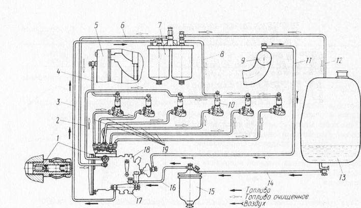
Fig. 21. Diagramă de alimentare cu combustibil pentru motorină SMD-31: 1 - supapă de clapetă; 2 - conducta de combustibil pentru ocolirea excesului de combustibil din capul pompei de combustibil; 3 - Linia de combustibil pentru alimentare cu combustibil de la pompa de pompare către filtrul fin; 4 - linia de scurgere a combustibilului de la primul și al doilea injector; 5 - o conductă de admisie a unui turbocompresor; 6 - conducta de combustibil pentru alimentarea cu combustibil curat a pompei de carburant; 7 - filtru de combustibil fin; 8 - linia de scurgere a combustibilului care dă consumul de combustibil de la injectoarele a treia, a patra, a cincea și a șasea; 9 - un colector de admisie; 10 - injector; 11 - conducta de alimentare cu aer a limitatorului de fum; 12 - Linia de combustibil pentru evacuarea combustibilului și ventilarea rezervorului; 13 - rezervor de combustibil; și - conducta de combustibil de la rezervorul de combustibil la filtrul grosier; Filtru 15-gros; 16 - conducta de combustibil de la filtrul grosier la pompa de rapel; 17 - pompă de rapel; 18 - pompă de combustibil de înaltă presiune; 19 - linii de combustibil
capul pompei de combustibil diesel SMD-23 merge la pompa de alimentare cu combustibil, iar SMD-31 la rezervor.
Filtrul de purificare a combustibilului brut FT-75 este proiectat pentru combustibilul pre-curățat. Se compune dintr-o carcasă, un distribuitor, un element filtrant care returnează particule mecanice mai mari de 0,09 mm.
Elementul de filtrare este amplasat în interiorul unei pahare din plastic atașată de corp cu un inel cu ajutorul șuruburilor de strângere. Etanșarea conectorului carcasei de sticlă se realizează prin intermediul unui inel de etanșare. În interiorul sticlei este un calmant. Elementul de conectare și conducta de combustibil sunt utilizate pentru alimentare, iar linia de combustibil 8 este utilizată pentru a scurge combustibilul din filtru.
Întreținerea filtrului este de golire a nămolului la fiecare 240 de ore și spălarea elementului de filtrare al amortizorului de zgomot și a corpului în 96 ... 1000 ore.
Înainte de efectuarea întreținerii închideți alimentarea cu combustibil a filtrului. Pentru a scurge bucata, deșurubați ștecherul și drenați nămolul în recipient. Apoi înfășurați dopul. La spălare, scoateți șuruburile 9, scoateți geamul. Scoateți reflectorul. Clătiți sticla, reflectorul și funinginea. Filtruți elementul de filtrare, scufundându-l repetat în combustibil curat.
Nu curățați plasa cu o racletă sau o perie și ștergeți-o cu cârpe!
Asamblați filtrul. Strângeți șuruburile în mod egal, pentru a nu deforma sticla și a nu rupe inelul de strângere.
Filtrul de curățare fină a combustibilului FT-150A este destinat curățării finale a combustibilului. Constă dintr-un corp din fontă, la care sunt atașate două secțiuni identice prin intermediul unor șuruburi de prindere care funcționează în paralel. Secțiunea este un pahar în care este instalat un element filtrant de hârtie ETP-75 pe fitinguri. Carcasa conectorului - sticla este sigilată cu un inel. În carcasa filtrului, sunt montate șuruburile de montare a conductei de combustibil. Pe linia de combustibil, combustibilul din pompa de pompare se îndreaptă către elementele de filtrare care trece prin care se curăță și intră în pompa de injecție din carcasă și din conducta de combustibil.
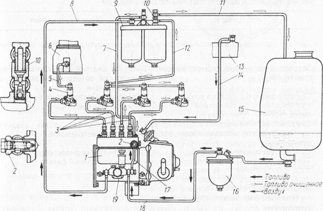
Fig. 22. Diagrama sistemului de alimentare cu combustibil diesel SMD-23: 1 - pompă de combustibil; 2 - ansamblul supapei de bypass; 3 - linii de combustibil de înaltă presiune; 4 - injectoare; 5 - linia de scurgere a combustibilului care dă consumul de combustibil de la primul injector; 6 - o conductă de admisie; 7 - Linia de combustibil pentru alimentarea cu combustibil curat a pompei de carburant; 8 - conducta de alimentare cu combustibil de la pompa de alimentare cu combustibil la filtrul fin; 9 - filtru de combustibil fin; 10 - supapa de îndepărtare a aerului (în timpul adunării); 11 - conducta de combustibil scurse excesul de combustibil și aerul de evacuare în rezervor; 12 - linia de scurgere a combustibilului care dă consumul de combustibil de la injectoarele a doua, a treia și a patra; 13 - un colector de admisie; 14 - conducta de alimentare cu aer a limitatorului de fum; 15 - rezervor de combustibil; 16 - filtru brut de combustibil; 17 - conducta de combustibil a bypass-ului de combustibil de la capul pompei de combustibil la pompa de alimentare cu combustibil; 18 g conductă de combustibil de la filtrul grosier la pompa de alimentare cu combustibil; 19 pompă de alimentare cu combustibil
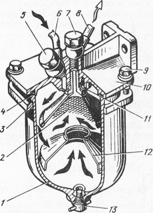
Fig. 23. Filtrul de curățare aspră a combustibilului: 1 - un geam; 2 - element filtrant (reflector); 3 - un inel de presiune; Inel de etanșare 4; 5 și 7 - bolțuri de unghiuri de cotitură; 6 - Linia de alimentare cu combustibil la combustibil; 8 - conducta de alimentare cu combustibil a pompei de alimentare; 9 - un bolț; 10 - carcasa filtrului; 11 - distribuitorul; 12 - dispozitivul liniștitor; 13 - un dop de deschidere pentru scurgerea unui sediment de combustibil
Întreținerea constă în golirea nămolului după 240 de ore și înlocuirea elementelor de filtrare în 960 ... 1000 ore sau, dacă este necesar, când presiunea din spatele filtrului scade la 0,06 MPa (0,6 kgf / cm2).
Pentru a scurge nămolul, scoateți ștecherul. Scurgeți nămolul într-un recipient special. După aceasta, strângeți dopul.
Când înlocuiți elementele, scoateți dopurile, evacuați nămolul. Înlocuiți dopurile. Răsuciți șuruburile de cuplare, scoateți ochelarii în vederea adunării. Scoateți elementele de filtrare. Clătiți ochelarii cu combustibil curat. Instalați elemente de filtrare noi. Reasamblați filtrul în ordine inversă.
Scoaterea aerului de la sistem de combustibil Când motorul diesel este în funcțiune și sistemul este pompat, acesta curge automat prin supapă.
Duza este concepută pentru a fi introdusă în cilindrii de pulverizare cu motorină. La motoarele diesel SMD-31 și SMD-23, este instalat un injector de tip închis 39.1112010. Pe corpul său, marcajul "39" este umplute. Duza constă dintr-o carcasă, o piuliță specială, cu care este montat pulverizatorul, având patru deschideri de duze dispuse asimetric care asigură o distribuție uniformă a combustibilului în camera de ardere. În legătură cu asimetria găurilor, corpul duzei este fixat ferm față de corpul injectorului cu două știfturi. Aspiratorul este presat pe corp cu ajutorul unui arc prin bara. Forța de inhalare a unui arc este reglată de șurubul care este fixat de provorot printr-un contra-tijă. Garnitura de etanșare este montată pe butucul carcasei injectorului. Din pompa de combustibil prin unire și filtru, combustibilul trece prin linia de combustibil de înaltă presiune în injector. Deoarece combustibilul intră canalele corpului nebulizator și când presiunea de 17,5 ... 18,0 MPa (175 ... 180kgs / cm2), învingând rezistența arcului, ridică acul și injectat în camera de ardere. Combustibilul de tăiere pentru găurirea în șurub prin capota și pătratul de întoarcere pătrunde în conducta de combustibil.
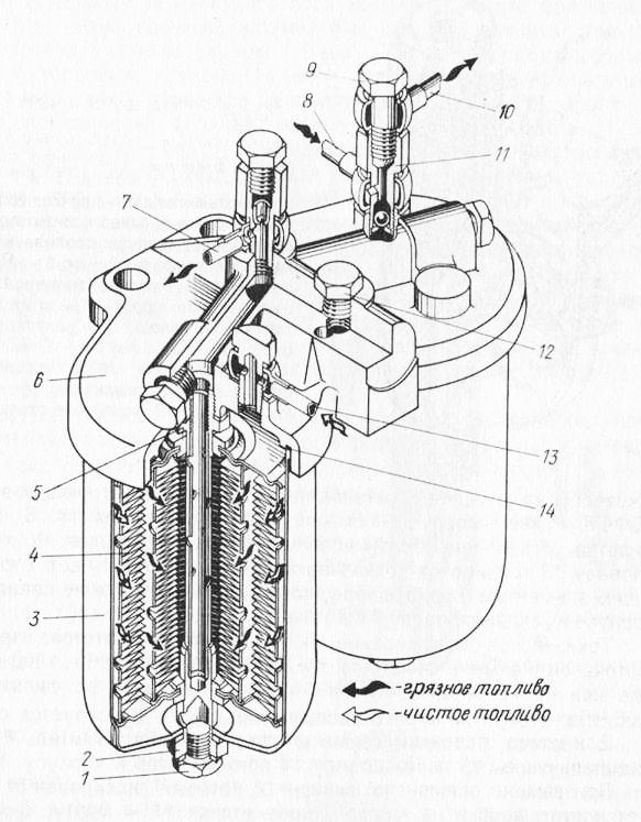
Fig. 24. Filtrul de curățare fină a combustibilului: 1 - un dop de deschidere de prune dintr-un sediment de combustibil; 2 - un bolț de cuplare, 3 - un geam; 4 - element filtrant; 5 - montare; 6 - carcasa filtrului; 7 - Linia de combustibil pentru alimentarea cu combustibil curat a pompei de carburant; 8 - conducta de evacuare a combustibilului care dă combustibil din a treia, a patra, a cincea și a șasea duza; 10 - Linia de combustibil pentru evacuarea combustibilului și ventilarea rezervorului; 11 - supapa; 12 - plută; 13 - conducta de alimentare cu combustibil din pompa de alimentare cu combustibil; 14 - Inel O
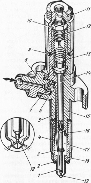
Fig. 25. Injector: 1 - pulverizator; 2 - o căptușeală a unui atomizor; 3 - camera în cazul unui nebulizator; 4 - canalul în cazul nebulizatorului; Cu 5 canale în carcasa injectorului; b - garnitura sindicatului; Filtru de 7 ochiuri; 8 - montare; 9 - o căptușeală; 10 - piulița de blocare; 11 - capacul; 12 - șurub de reglare; 13 - un izvor; 14 - tija; Corpul 15 al duzei; 16 - știftul de reglare; 17 - nebulizator; 18 - piulițele de pulverizare; 19 - deschiderea duzei
Întreținerea injectorului constă în verificarea periodică și, dacă este necesar, ajustarea presiunii injecției de combustibil și a calității pulverizării sale. Operațiunea se efectuează în timpul orelor de funcționare de 960 ... 1000 ore când se pregătește combinația pentru sezonul de recoltare.
Pentru a conduce întreținere scoateți injectoarele de la motorină. În acest caz, cheia (14 mm), deconectați scurgerea de combustibil, o cheie (19 mm), - conducta de combustibil de înaltă presiune, cheia tubulară (14 mm) - piulițele duză. Scoateți injectoarele și verificați KI-562. Presiunea de injecție a carburantului începe să fie de 17,5 ... 18,0 MPa (175 ... 180 kg / cm-1) stropite - fără strueobrazovaniya, clar cutoff, exprimat.
Dacă este necesar să reglați presiunea de injecție a combustibilului, instalați injectorul în dispozitivul MP-1613A (inclus în kitul KI-562). Utilizați un chei (19 mm) pentru a deșuruba și scoate capacul duzei și rotiți piulița de fixare a șurubului de reglare cu 2 până la 3 rotiri cu o cheie (14 mm). Scoateți duza de pe dispozitiv și conectați-o la dispozitivul KI-562. Umpleți canalele injectorului cu combustibil, făcând pârghia instrumentului cu 60 ... 80 curse pe minut, până la injecția de combustibil din nebulizator. Determinați presiunea de la pornirea injecției în funcție de manometrul și, dacă este necesar, reglați strângerea arcului cu un șurub folosind o șurubelniță.
În cazul unei pulverizări necorespunzătoare (la presiunea de pornire a injecției), scoateți duza de la instrument și instalați-o pe dispozitivul KI-1613A. Deșurubați piulița de fixare a piulițelor de pulverizare cu o cheie (19 mm) și scoateți pulverizatorul. Curățați cu ajutorul unui răzuitor de lemn acul pistolului din depozit. Orificiile duzei pistolului de pulverizare trebuie curățate cu ajutorul unei scule atașate la piesele de schimb ale motorului diesel, spălați pistolul de pulverizare. Dacă găurile nu sunt curățate, puneți-le timp de 5 ... 10 minute într-o baie cu kerosen și curățați din nou. Asigurați-vă că piesele de împerechere sunt curate și asamblați injectorul în ordine inversă.
În cele din urmă piuliță nebulizator piulița de reglare de blocare filetat și capac de cuplu de strângere, respectiv egală cu 55 ... 70 Nm (5,5 kgf ... 7,0 m), 20 ... 25 N m (2,0 m ... 2,5 kgf), 90 ... 110 N-M (9,0 ... 11,0 kgf m).
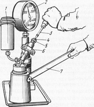
Fig. 26. Verificarea și ajustarea injectorului cu KI-562:
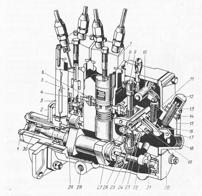
Fig. 27. Pompa de combustibil presiune inalta ND-22/6: 1 - manson de antrenare cu carlige; 2 - acoperiș pentru rulmenți; 3 - flanșă de montare; l - o roată intermediară sertizată a dispozitivului de rotație a pistonului; 5 - cazul pompei de combustibil; 6 - suport intermediar roată dințată; 7 - secțiune de presiune înaltă; 8 - plută; 9 - arbore regulator; 10 - maneta unui arc al unui regulator; 11 - izvorul autorității de reglementare; 12 - capacul corectorului; 13 - oprirea corectorului; 14 - piuliță de oprire; 15 - coperta autorității de reglementare; 16 - pârghia corectorului; 17 - pârghia furcii regulatorului; 18 - Bonk pentru instalarea limitatorului de fum; 19 - o axă a unui cercel al unui arc; 20 - capacul transmisiei; 21 - un împingător al unei pompe de alimentare cu combustibil; Arbore 22 excentric; 23 - centrul de reglementare; 24 - roată cu roată cu roată dințată; 25 roți dințate; 26 - arc de amortizor; - axa dispozitivului de reglare a levierului furcii; 28 - o gaură pentru golirea uleiului din carcasa pompei de combustibil; Arbore cu 29 de camă; 30 - o piuliță de fixare a prizelor pentru spițe
După montare, verificați presiunea de pornire a injecției și calitatea pulverizării.
Montați duză pe motorină, acordând atenție prezenței și stării tehnice a garniturii (vezi Figura 25). Pompa de combustibil a motorului diesel SMD-31. Pompa de combustibil ND-22/6 a tipului de distribuție este instalată pe motorul diesel SMD-31, proiectarea căruia este prezentată în figura 27.
Pompa combustibilului este echipată cu un regulator mecanic cu acțiune directă, o pompă de pompare a combustibilului de tip piston și un limitator de fum. În carcasa din aluminiu a pompei de combustibil există trei cavități: pompă, regulator și mecanism camă.
În cavitatea de pompare există două perechi de plonjoare care alimentează, în timpul strict definit, cantitatea necesară de combustibil din cilindri.
O secțiune furnizează combustibil la primul, al doilea și al treilea și la celălalt la buteliile 4, 5 și 6. Când arborele cu came se rotește, pistonul efectuează o mișcare alternativă și rotativă. Injectarea combustibilului are loc atunci când camul lovește rola de împingere și aspirația - când se scurge cama sub acțiunea unui arc de întoarcere. Mișcarea de rotație a pistonului asigură distribuția combustibilului de-a lungul cilindrilor.
O schimbare (creștere sau scădere) a alimentării cu combustibil și oprirea completă a pompei are loc atunci când distribuitorul este deplasat axial de-a lungul pistonului de către un regulator printr-un sistem de pârghii.
Regulatorul pompei de combustibil a motorului diesel SMD-31. În secțiunea de reglare a pompei de combustibil, există un regulator mecanic cu acțiune totală, cu acțiune directă, cu corecție pozitivă și îmbogățire automată a carburantului. Acesta este conceput pentru a menține o viteză predeterminată a arborelui cotit al unui motor diesel, atunci când schimbările de sarcină, limita de viteză într-o denivelare predeterminată și să asigure funcționarea stabilă a motorului diesel în diferite condiții.
Pe rola camă a pompei de combustibil există o roată dințată frontală angrenată cu angrenajul acționat pe arborele regulatorului. Când arborele cu came al pompei se rotește prin intermediul unei perechi de roți dințate, actuatorul este acționat.
Pe arborele regulatorului există un butuc, din care greutățile sunt articulate.
Sub acțiunea bunurilor, cuplajul situat pe butuc are posibilitatea de mișcare axială. Al doilea capăt al cuplajului se află pe pârghia furcii, care se află pe aceeași axă cu pârghia de corector. Pârghia de pivotare, la rândul său, este conectată la dispozitivele de măsurare cu ajutorul sistemului de tracțiune, iar pârghia de reglare încărcată cu arc este conectată la pârghia de comandă externă. Butucul este conectat la arborele regulatorului printr-un arc de amortizare. În butuc este introdus pinul care este introdus în canelura șaibei de blocare a arborelui regulatorului. Acest design elimină posibilitatea de "spațiere" a motorului diesel atunci când arcul clapetei se desprinde. Transferul rotației de la arbore la butucul mărfurilor prin șaibă și pin.
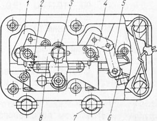
Figura 28. Diagrama controlului dozatoarelor (formularul din stânga cu capacul îndepărtat): 1 - Bucșa dispozitivului de dozare; 2 - arcul de pornire; 3 - o coloană de roată intermediară; 4 - pârghia unei mișcări de acționare a unui dozator; 5 - draft; 6 - degetul excentric; 7 - blocarea împingătorului; 8 - tija de ajustare
Odată cu creșterea vitezei de ambreiaj, sub acțiunea forței de mișcări centrifuge de marfă și de cotitură pârghie furcă și un arc de pârghie se extinde corectorului, provocând dozatoare instalate în poziția de aprovizionare. Atunci când viteza de rotație este redusă, are loc mișcarea inversă, adică dozatoarele sunt deplasate într-o poziție de alimentare mai ridicată.
Figura 28 prezintă schema de control a dispozitivelor de măsurare (vedere din stânga cu capacul îndepărtat). Sub acțiunea arcului deplasează pârghia egalizatorului este montat într-o furcă arcuri pârghie cu clearance-ul și conectat la acesta printr-o axă dozatoare cercel traducere ora de începere a unei poziții creștere de combustibil diesel.
Pompa de combustibil a pompei de carburant de înaltă presiune a motorinei SMD-31 este montată pe carcasa pompei de combustibil folosind două știfturi și piulițe. Este proiectat pentru alimentarea combustibilului din rezervor către filtrul fin și pentru pomparea manuală a sistemului de alimentare cu motor diesel. Treceți de la arborele excentric prin rola.
Pompa este alcătuită dintr-o carcasă din fontă, a cărei orificiu orizontal este un piston, apăsat pe tija printr-un arc așezat pe cel de-al doilea capăt al unei plută. Pe o axă cu pistonul în forajul caroseriei este montată o presă cu role. În găurile din partea inferioară a corpului există supape de admisie și evacuare presate pe scaune prin arcuri și dopuri. O pompă de combustibil este atașată pompei de combustibil, care pompează aerul din sistemul de alimentare cu combustibil diesel.
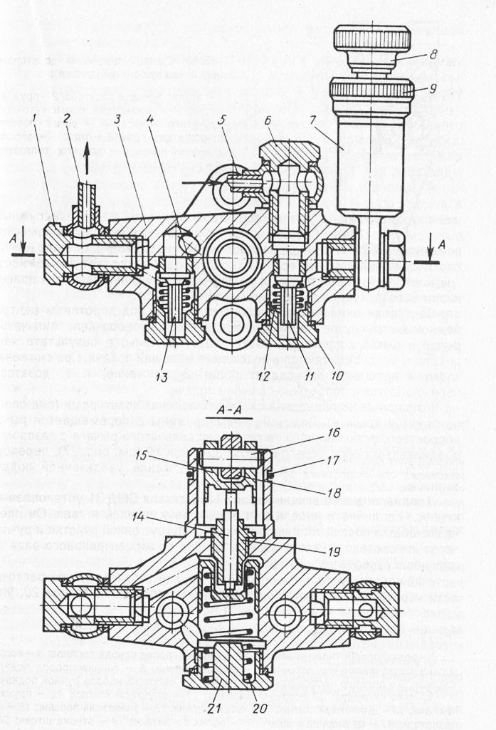
Fig. 29. Pompă de alimentare cu combustibil a pompei de combustibil a motorului diesel SMD-31: 1 și 6-bolțuri de pătrată; 2 - o conductă de scurgere a combustibilului; 3 - carcasa pompei de alimentare cu combustibil; 4 - o șa de valvă; 5 - conducta de alimentare cu combustibil; 7 - cilindrul pompei de pompare manuală; 8 - mânerul pompei manuale; 9 - capacul cilindrului; 10-fișă; 11 - supapa de admisie; 12 - un arc al supapei; 13 - supapa finală; 14 - tija pistonului; 15 - un împingător al pistonului; 16 - axul împingătorului; 17 - un inel de blocare; 18 - o rolă de împingător; 19 - Bucșă de tulpină; Arc cu 20 de pistoane; 21 - un dop de primăvară
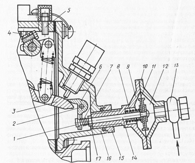
Fig. 30. Limitatorul de fum și instalarea acestuia pe piulițele de blocare SMD-31: 1 și 18; 2 axe ale opritorului mobil; 3 - pârghia corectorului; 4 șurubul de oprire a alimentării cu combustibil a pompei; 5 - șurubul opritor al limitei de viteză maximă a unui motor diesel; 6 - opritor mobil; 7 - arcul opririi mobile; 8 - arcul limitatorului de fum; 9 - cazul limitatorului de fum; 10 - capacul limitatorului de fum; 11 - diafragma; 12 - cavitatea de lucru; 13 - un tub de intrare a aerului de la un colector de admisie; 14 - stem; 16 - coperta autorității de reglementare; 17 nuci
Limitatorul de fum este instalat pe pompa de carburant pentru a asigura curățenia mediului motorului diesel (reducerea fumului gazelor de eșapament) și pentru a îmbunătăți economia motorinei în modurile de funcționare tranzitorii. Designul limitatorului de fum este prezentat în Figura 30.
Opritorul constă dintr-un corp, o diafragmă și o tijă conectată la diafragmă. La capătul tijei este o oprire mobilă, care se rotește pe axă.
Când motorul este accelerat (deplasând maneta de comandă spre creșterea alimentării cu combustibil), arcul prin tija și opritorul mobil limitează mișcarea pârghiei de corector pentru a crește alimentarea ciclică a combustibilului. Limitarea mișcării pârghiei de corectare are loc până la atingerea presiunii stabilite a aerului de încărcare. Forța de la această presiune de aer care vine din receptor prin tub în cavitatea corectorului pneumatic este percepută de diafragmă. Acestea din urmă sub acțiunea presiunii aerului de supraalimentare, împotriva forței arcului deplasează tija pistonului spre regulatorul electronic și elimină gardul mobil din pârghia egalizatorului, eliminând restricția de creștere a ciclului de alimentare cu combustibil, valoarea maximă care este reglat pe stand.
Datorită faptului că lubrifierea forțată a pompei de combustibil (circulație), realizată prin sistemul de lubrifiere al unui motor diesel, întreținerea acestuia este periodică (960 ... prin 1000 de ore), verificarea pe standul motorless și, dacă este necesar, ajustarea parametrilor de funcționare a pompei de carburant.
După scoaterea pompei de la motorină, aceasta trebuie ștersă cu o cârpă înmuiată în apă curată combustibil diesel, fixați pe suport, turnați 100 ... 120 mm3 ulei în corp și efectuați următoarele preparate:
- fixați pompa pe suport. Libera circulație în cuplare nu este permisă mai mult de 1 °;
- opriți limitatorul de fum prin înșurubarea corpului 9 împotriva opritorului în capacul regulatorului 16;
- conectați sistemul de alimentare a bancului cu pompa de alimentare cu combustibil fără a strânge complet piulița din racordul de alimentare cu combustibil la pompă;
- pomparea sistemului de alimentare cu combustibil până la apariția unui jet continuu (fără bule de aer) de sub racordul de combustibil, apoi strângeți piulița;
- pompa de alimentare cu combustibil pentru a pompa sistemului până la o presiune de 0,06 ... în acesta 0,1 MPa (0,6 ... 1,0 kgf / cm2) și manual rotiți axul stativ până combustibil printr-o montare de înaltă presiune a pompei; - Conectați conductele de combustibil la presiune ridicată la pompă;
- fixați maneta de comandă a pompei în poziția maximă de alimentare și porniți suportul;
- pomparea sistemului de înaltă presiune până când injectorii de carburant sunt injectați în mod clar (viteza arborelui este de 400 ... 600 min-1).
Reglarea alimentării cu combustibil la frecvența de rotație de pornire. Reglarea se face cu ajutorul unui deget excentric și a unei modificări a lungimii forței. Măriți alimentarea prin rotirea în sensul invers acelor de ceasornic, în sensul scăderii - în sensul acelor de ceasornic.
Verificați începutul regulatorului. Setați viteza corespunzătoare începutului regulatorului. Deșurubați opritorul de la capac, reglați alimentarea cu combustibil cu un șurub, astfel încât să corespundă alimentării ciclice medii prin fitinguri la viteza nominală, apoi înșurubați șurubul.
Ajustarea alimentării nominale a combustibilului. Setați viteza nominală a arborelui cu came. În capacul regulatorului, înșurubați corectorul pre-ajustat la viteza nominală. Întoarcerea corectorului - coborârea, rotirea - creșterea cantității de combustibil. După stabilirea vitezei, strângeți piulița de blocare a corectorului. Verificați alimentarea neuniformă a combustibilului, care nu trebuie să depășească 3 ... 4%. Reducerea neuniformității poate fi datorată selecției supapelor de injecție și de revenire și a arcurilor acestora.
Verificați alimentarea cu combustibil la o viteză maximă de ralanti. Setați viteza maximă de mers în gol și măsurați alimentarea cu combustibil. Se calculează inegalitatea furajului, care nu trebuie să depășească 35%.
Verificați viteza corespunzătoare opririi totale a regulatorului de debit de combustibil. Creșteți cu ușurință alimentarea cu combustibil prin antrenarea suportului, urmărindu-i ieșirea de la duzele bancului. Când ieșirea combustibilului se oprește, se înregistrează viteza tahometrului din bancă. Dacă frecvența este incoerentă, se schimbă numărul de bobine de acționare ale arcurilor de reglare. Pentru a crește cantitatea de combustibil, reduceți numărul acestora și reduceți - creșteți.
Valorile de reglare a parametrilor pompelor de combustibil
Verificați și reglați unghiul de reglare a avansului de injecție a combustibilului. După îndepărtarea și instalarea pompei de combustibil asociată cu întreținerea (după 960 ... 1000 ore de funcționare) sau eliminarea defecțiunilor, este necesar să verificați unghiul de setare al avansului de injecție a combustibilului.
Verificarea trebuie efectuată în următoarea ordine:
- Deconectați conducta de combustibil de înaltă presiune a primului cilindru de la unitatea de pompare;
- Momentoscop (o bucată de țeavă de combustibil de înaltă presiune, la care este conectat un tub de sticlă cu un diametru interior de 1 ... 2 mm cu ajutorul unui tub de cauciuc sau policlorură de vinil);
- scoateți aerul din sistem folosind o pompă manuală de combustibil; - Scoateți capacul frontal al cilindrului și capacul gurii de vizitare de pe carcasa volantului;
- Montați pistonul primului cilindru în VMT. cursa de compresie, pornirea arborelui cotit;
- sfert provernuv arborelui cotit rotiți în sens antiorar (din partea ventilatorului), se observă nivelul de combustibil într-un tub de sticlă momentoskopa se rotește încet arborele cotit în sensul acelor de ceasornic. La începutul ridicării carburantului, opriți rotirea arborelui cotit;
- determinarea pe scară a unghiului de reglare a avansului de injecție a combustibilului, care trebuie să fie de 27 ... 300 până la m.
Fig. 31. Verificarea unui colț de reglare a avansării injecției de combustibil: 1 - un tub de sticlă (моментоскоп); Tub de 2 tuburi din cauciuc; 3 - conducta de combustibil de înaltă presiune; 4 - piulița de legătură; 5 - unirea pompei de combustibil a primului cilindru
Dacă unghiul de reglare a avansării injecției de combustibil nu corespunde cerințelor, este necesar să o reglați în următoarea ordine:
- scoateți contorul de oră;
- Îndepărtați două șuruburi de fixare a dopurilor;
- dacă este necesar, creșterea unghiului de injecție de combustibil în avans (primind unghi mai devreme) roti în raport cu roata dințată de antrenare a pompei cu fantă cu flanșă de-a lungul drum, și de a reduce - invers acelor de ceasornic. Mișcarea flanșei la o gaură corespunde unei modificări a unghiului cu 3 ° a rotației arborelui cotit.
Pompa de combustibil a motoarelor diesel SMD-23/24. La motoarele diesel pompa de combustibil este instalat tip V14M.80.16001 LSTN, chetyrehplunzherny, rotire dreapta, cu un piston cu diametrul de 10 mm.
Pompa este atașată cu patru șuruburi la carterul cutiei de viteze și un bolț la suportul special. Pentru alimentarea cu combustibil a tampoanelor pistonului, în capul pompei se face un canal P-oasis. La un capăt al canalului 16 este conectat combustibilul alimentarea cu combustibil de la filtrul de combustibil secundar și la celălalt - bypass combustibil surplus de combustibil din capul pompei în pompa toplivopod-kachivayuschy. Robinetul de bypass este montat în fitingul conductei de combustibil.
În partea inferioară a carcasei pompei are o flanșă pentru instalarea pompa de transfer și un orificiu de admisie a uleiului, un capac închis. Pentru inspectarea și reglarea pompei, trapa este prevăzută pe corp, acoperită cu un capac.
Lubrifierea pompei de carburant circulă din sistemul de lubrifiere diesel. Din principala galerie de ulei este alimentat motorină din placa de montare a pompei în spațiul liber dintre orificiul de ghidare al carcasei pompei și impingatoare, părți ale pompei și controlerul de ungere. Atunci când un anumit nivel al uleiului pe canalul din carcasa pompei se unește în angrenajul carter, și apoi - capacul inferior al unui carter al motorului diesel.
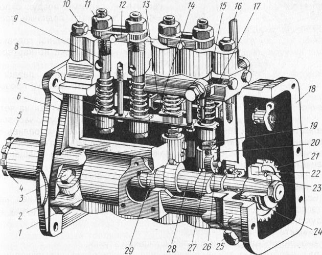
Fig. 32. Pompa de combustibil de presiune înaltă a unui motor diesel SMD-23:
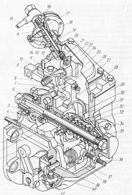
Fig. 33. Regulatorul pompei de combustibil a motorului diesel SMD-23:
Pompa de combustibil LSTN este echipată cu un regulator automat de reglare a tipului centrifugal.
Regulatorul de pompare a carburantului LSTN este proiectat să mențină turația specificată a motorului atunci când sarcina se schimbă, limitând viteza de rotație în cadrul neuniformității specificate și asigurând funcționarea stabilă a motorului diesel în diferite moduri.
Regulatorul este atașat la flanșa posterioară a carcasei pompei de combustibil. Arborele se rotește pe două rulmenți cu bile (figura 33). Acționați regulatorul de la arborele cu came al pompei de combustibil printr-o pereche de roți dințate.
Când motorul diesel funcționează fără sarcină la viteza maximă, furca este în poziția cea mai din spate, adică este asigurată alimentarea minimă cu combustibil. Pe măsură ce crește sarcina, furca se deplasează înainte, adică alimentarea cu combustibil crește.
Șaibele sunt instalate pentru a regla elasticitatea arcurilor. Creșterea sau scăderea vitezei motorului se realizează prin schimbarea numărului de garnituri de sub bolț. Ajustarea se face de către producător.
Pompă de injecție de carburant 80.16.085 tip piston. Este proiectat pentru alimentarea cu combustibil de la filtrul grosier la pompa de carburant și pentru pomparea manuală a combustibilului în sistem. Acționați combustibil pomparea pompei de la excentricul situat pe arborele camă al pompei de combustibil. Proiectarea pompei de combustibil este prezentată în figura 34.
Întreținerea pompei de combustibil constă într-o inspecție periodică (după 960 ... 1000 ore) și, dacă este necesar, ajustarea acesteia într-un atelier special de la stand. Pompa de pe suport este testată complet cu duze de banc.
Hrănirea secțiunile LSTN pompei de combustibil depinde de șine de deplasare (fig. 35), definit de distanța față de planul pompei de împerechere pentru a pompa primului element clemă să fie de 10,5 ... 11,0 mm. Această distanță este măsurată cu un etrier în două poziții extreme. Ajustarea constă în înșurubarea (scăderea) alimentării) sau prin rotirea I (creșterea alimentării) șurubului.
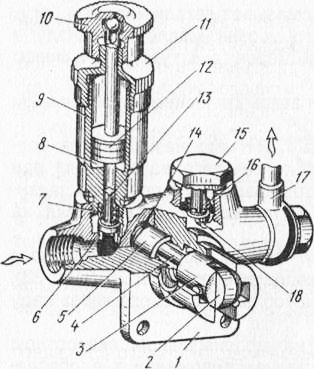
Fig. 34. Pompa de alimentare cu combustibil a motorului diesel SMD-23: 1 - corp; 2 - o rolă a unui împingător; 3 împingător; 4 - stem; 5 - pistonul combustibilului - vypodkachivajushchego pompa; 6 - bucșa; 7 și 16 ale arcului de supapă; 8 - garnitura pistonului; Pompă de alimentare cu combustibil cu 9 cilindri; 10 - mânerul; 11 - capacul cilindrului; 12 - pistonul pompei de pompare a combustibilului; 13 - supapa de admisie; 14 - un izvor; 15 - plută; 17 - conducta de alimentare cu combustibil a filtrului de combustibil fin; 18 - supapă de livrare
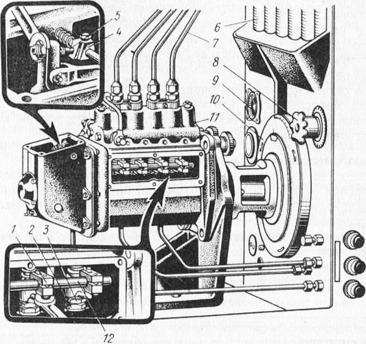
Fig. 35. Reglarea pompei de combustibil:
Când verificați sau reglați pompa de combustibil în modul nominal sau modul de cuplu maxim, setați rotația nominală a arborelui cu came al pompei. După 2 minute de funcționare a pompei de combustibil se măsoară de două până la trei ori consumul de combustibil și se măsoară alimentarea medie a secțiunii.
Reglarea alimentării cu combustibil a secțiunilor se face prin deplasarea clemei necesare pe șina pompei. În cazul în care alimentarea cu combustibil ar trebui să fie redusă, este necesar să slăbiți șurubul de fixare clema și deplasați clema în direcția de reglementare. Pentru a mări alimentarea cu combustibil, clema este deplasată pe partea unității.
La stand, setați viteza corespunzătoare cuplului maxim, măsurați consumul de combustibil și calculați debitul mediu al fiecărei secțiuni.
Alimentarea cu combustibil este reglată în modul de cuplu maxim, schimbând poziția prismei pe axul de ghidare. Dacă cantitatea de combustibil trebuie să fie redusă, prisma ar trebui să fie redusă, dacă crește - apoi ridicați.
După modul de control al carburantului la cuplul maxim este necesar pentru a verifica debitul la viteza nominală și debutul acțiunii regulatorului. Dacă este necesar, ajustați.
K Categorie: - Întreținerea dieselului
Sistemele de alimentare diesel includ de obicei, rezervoare de consumabile pentru combustibil, fose septice, pompe de rapel, alimentarea cu combustibil din rezervor în cavitatea de primire a carburantului combustibil de joasă presiune filtre grosiere și filtre fine sunt instalate pe conducta de presiune joasă, filtre de combustibil de presiune înaltă, combustibilul să se scurgă combustibil ocolit și alte elemente. În funcție de tipul de sistem de alimentare, unele dintre aceste elemente pot lipsi, altele pot fi combinate într-unul sau mai multe elemente introduse. Ca rezultat, se creează sisteme de combustibil de diferite tipuri, este dificil să se dea o clasificare suficient de substanțială. Influența decisivă asupra proiectării sistemului de combustibil diesel este asigurată de modul de alimentare și pulverizare a combustibilului.
Prin metoda de hrănire și pulverizare, sistemele de putere ale motoarelor diesel moderne sunt împărțite în:
- sisteme directe
- sisteme de baterii
Sisteme de alimentare directă Acestea sunt utilizate pe scară largă la motoare diesel în diverse scopuri. Elementele de bază ale acestui sistem sunt pompa de înaltă presiune, injector, filtre filtre grosiere și fine, unitate de piston de înaltă presiune. Prin metoda de antrenare a pistonului, aceste sisteme sunt împărțite în sisteme cu acționări mecanice, gaz, arc și pneumohidraulic.
Fig. Tipuri de sisteme de alimentare cu energie electrică pentru motoare diesel
Diagrama schematică a sistemului de putere al motorului diesel mecanic condus pistonul pompei de înaltă presiune este prezentat în figură. Combustibil intră în sistemul din rezervorul 1 printr-o purificare Filtru grosier 2 prin pompa de alimentare 3 și alimentat prin filtru de purificare fină 5 în spațiul de recepție 6, pompa de înaltă presiune. Ventilele de bypass 4 și 11 mențin o anumită presiune în sistem, redind excesul de combustibil de la conductele de combustibil 12 către rezervor. Presiunea în conducta de alimentare controlată de manometru 10. Pompa de presiune ridicată cuprinde secțiuni separate, numărul cărora este egal cu numărul de cilindri, măsura în conformitate cu modul de funcționare a anumitor porțiuni de combustibil diesel, comprimă și furnizează presiunea de refulare a unui carburant prin filtrul de înaltă presiune 7 și injectorul 8 camera de combustie 1 într-o fază predeterminată a procesului de lucru al motorului. Scurtat prin golurile din pompă și injectori, combustibilul este luat de la conductele de combustibil 12 la rezervorul de combustibil. Adesea, combustibilul este utilizat pentru a răci duza în condiții de temperatură severă. În acest caz, sunt furnizate conducte suplimentare pentru alimentarea și îndepărtarea combustibilului de răcire la injector.
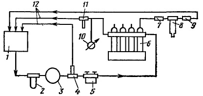
Fig. Diagrama alimentării cu energie a unui motor diesel cu acționare mecanică a unui piston de pompă de înaltă presiune:
1 - rezervor de combustibil; 2 - filtru grosier; 3 - pompă de rapel; 4, 11 - supape de by-pass; 5 - filtru fin, 6 - pompă de înaltă presiune; 7 - filtru de înaltă presiune; 8 - injector; 9 - filtrul liniei de combustibil by-pass; 10 - manometru, 12 - conducte de scurgere a combustibilului
In exploatarea sistemelor de alimentare este posibilă pătrunderea aerului în combustibil de joasă presiune prin compuși scurgeri precum formarea de vapori de curgere trei discontinuități. Este extrem de nedorit să se introducă astfel de vapori în conducte, deoarece acestea încalcă munca corectă sistem. Pentru a elimina acest fenomen dăunător în zonele cu potențial de acumulare de gaze pentru eliberarea lor stabili supape cu ac asigură circulația continuă a combustibilului în sistem, care rezultă în gazele antrenate și combustibilul este evacuat în rezervorul de unde acestea pot fi eliminate.
În sistemele de combustibil pentru piston de pompă de înaltă presiune condusă de gaz prin piston auxiliar care acționează gazele cilindru diesel. Utilizarea gazelor face mult mai ușor proiectarea unității. Din acest punct de vedere, utilizarea sistemelor de combustibil cu un sistem de acționare cu gaz este promițătoare pentru motoarele diesel marine puternice. În plus, motoarele diesel marine cu un astfel de sistem de alimentare nu necesită instalarea unei trepte de viteze speciale.
Pompa de înaltă presiune, cu o cursă de aspirație condusă de gaz a pistonului 2 se realizează trei intermediul unui arc 4. Atunci când marginea superioară a pistonului în orificiul de umplere deschis 3, combustibilul intră în manșonul plunger camera H. Pistonul de gaz 6, în care (dislocă aerul prin ac ștrangulare 9 și conducta 10 în cilindrul motorului. La momentul depunerii gazelor combustibile cilindru prin supapa 11, iar acul 9 primește un efect de piston pe ea, forțând mișcare ascendentă. Pompa plunger după fereastra de suprapunere 3 și comprimă combustibilul prin supapa de evacuare 1 ia în sistem prin duza de injecție. hrăni controlul se face prin rotirea pistonului 2 prin intermediul dispozitivului 5, care permite schimbarea poziției marginii de reglare a ferestrei, în raport cu pistonul P 3. piston gaz Inelul cu compresie sigiliu 7, iar starea sa de temperatură este menținută de apă care circulă printr-o manta de apă 8. În funcționarea normală a limitatoarele de deplasare a pistonului de gaz furnizează amortizor de vibrații pe ambele părți.
Fig. Diagrama pompei de înaltă presiune cu piston acționat cu gaz:
1 - supapa de refulare, 2 - plonjor 3 - fereastră 4 - resort 5 - rotator, 6 - piston cu gaz, 7 - inelul de compresie, 8 - manta de apă 9 - ac 10 - pasajul de alimentare cu gaz; 11 - gaz robinet, B - marginea superioară; H - spațiu supra-plonjor, margine de reglare P
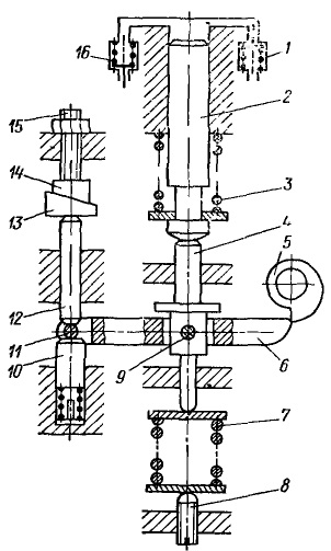
Fig. Schema pompei de injecție cu antrenare plonjor cu arc:
1 - supapa de livrare; 2 - un piston, 3 - un arc de piston; 4 - un împingător; 5 - o camă, 6 - maneta unui împingător; 7 - un arc, 8 - o placă de reglare a unui arc; 9 - axa pârghiei; 10 - piston de amortizare, 11 - opritorul manetei; 12 - tija, 13 - pană inferioară; 14 - pană superioară; 15 - șurubul; 16 - supapa de aspirație.
În sistemele de combustibil cu un arc-condus de înaltă presiune a pistonului pompei de combustibil cama nu acționează asupra pistonului, și o pârghie specială cu arc. La ciocnirea proeminentă 5 a tachetului pe pârghia 6, axa 9 asociată cu elementul de împingere 4, arcurile de compresiune 7 are loc și acumularea de energie în ea. Plonjorul 2 astfel sub acțiunea elastică a pistonului 3 se deplasează în jos și prin supapa de aspirație 16, combustibilul intră în manșonul pompei. După ce a scăpat (porțiunea proeminentă a camei cu pârghia arcul de presiune deplasează pistonul 4, și cu ea pistonul 2 în sus. În acest combustibil prin supapa de injecție 1 este alimentat în conducta de combustibil și prin, duza în camera de ardere. Supply are loc atâta timp cât elementul de împingere 4 nu se sprijină pe proeminența sa în ghidaj. Pretensionarea arcului 7 este reglată cu un șurub 8.
Alimentarea ciclului este modificată utilizând o pană inferioară 13 conectată la regulator. Când pivotul este deplasat spre dreapta, tija 12 se mișcă în jos. De aceea, se deplasează în jos și pârghia de rezemare 11 a elementului de împingere 6, iar capătul din dreapta al pârghiei este ridicată. Partea proeminentă a camei înainte de a atinge capătul din dreapta al pârghiei, astfel încât mai devreme va crește cursa de absorbție și eficientă a pistonului. Când penei inferior 13 este deplasat spre stânga de amortizare a pistonului 10 se deplasează dopul din 11 al pârghiei de împingere 6 în sus, pârghia cu camă 6 atingeri mai târziu cursă utilă de împingere a pistonului este redusă, reducându-se astfel ciclul de hrănire.
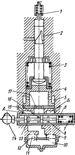
Fig. Diagrama pompei de injecție cu antrenare pneumohidraulică a pistonului:
A - cavitatea de primire, B - cavitatea de scurgere; 1 - supapa de livrare; 2 - piston; 3 - arcul pistonului; 4 - un împingător; 5 - o cavitate a amortizorului; 6 - cilindru supapă; 7 - un izvor de bobină; 8 - slotul drept; 9 - accentul; 10 - camera; 11 - cavitate pentru fluidul de lucru; 12 - membrană; 13 - fantă stângă; 14 - cama; 15 - canal de alimentare cu combustibil; 16 - fanta centrală; 17 - găuri de scurgere
Uniformitatea distribuției combustibilului pe cilindrii individuali este reglată de către panoul superior 14 prin intermediul unui șurub 15.
În sistemele de combustibil cu acționare pneumo-hidraulică a pistonului, combustibilul servește simultan ca lichid de lucru al servomotorului. Pompa de angrenaj pe canalul 15 alimentează carburantul la o presiune de 7 MPa față de volumul A al cilindrului 6 al bobinei. La poziția corespunzătoare a bobinei, cama de comandă 14, combustibilul curge prin fantele 13 și 16 în cavitatea 11. Pentru combustibil de presiune de stabilizare în această cavitate, prin membrana 12, un arc operează camera de aer 10. Deplasarea în sus a membranei este limitată la bontului 9. sub acțiunea pistonului presiunii carburantului 4 se deplasează în sus, trăgând pistonul 2 și după suprapunerea combustibilului orificiu de aspirație prin supapa de injecție 1 și curge în interiorul duzei de combustibil. amortizor hidraulic având o cavitate 5 limitează mișcarea elementului de împingere superior și previne posibilele lovituri pe bonturi cu o scădere bruscă a forței de piston la momentul cutoff. După oprirea alimentarea plunger valvei sub acțiunea arcului 7, iar când rotație cu came se deplasează spre stânga, conectarea prin orificiul 17, iar volumul decalaj a clapetei 8 sub pistonul de golire cavitatea B. Sub influența unei pompe piston de arc 3 efectuează o cursă de aspirație și deplasează simultan pistonul în jos. Prezența găurilor de scurgere 17 previne mișcările ascuțite ale pistonului, care afectează negativ funcționarea întregului sistem. Creșterea bruscă a pistonului este însoțită de modificarea nefavorabilă a cantității de injecție și aterizare bruscă ar putea perturba continuitatea fluxului în spațiul de aspirație și se degradează umplerea camerei de pompare.
Folosirea actuator fluid elimină rola cu came greoaie pentru a elimina influența deformarea elastică asupra parametrilor de injecție pentru a extinde gama de condiții stabile de viteză și de sarcină ale motorului diesel ca rezultat al parametrilor de stabilizare a procesului de lucru a sistemului. Cu toate acestea un design de acționare pneumohidraulică este complicată de instalarea unui mecanism special de auto-alimentat, care împiedică pe scară largă încă punerea în aplicare a acestuia.
Toate sistemele considerate cu injecție directă de combustibil pot fi împărțite în două grupuri prin conectarea pompei și a injectorului. Primul grup include sisteme în care pompa și injectorul sunt conectate printr-o linie de injectare de înaltă presiune, iar al doilea grup constă din sisteme cu o pompă combinată și injector în aceeași unitate, numită pompa injectorului. În sistemele cu pompe de injecție, nu există nicio linie de injectare, deci nu există riscul unor injectări suplimentare nedorite și al efectului fluctuațiilor elastice ale combustibilului în sistemul de înaltă presiune asupra fluxului de injecție. In plus, a redus semnificativ volumul de combustibil prezent între pompă și duză și injecție caracteristic profilului, prin urmare, mai puțin distorsionat dat cama crește presiunea medie de combustibil și unghiul de injecție lag scade. În consecință, sistemul de alimentare cu combustibil are o formă mai compactă.
Dezavantajele sistemelor cu pompe-injectoare includ:
- complexitatea și complexitatea structurii;
- complexitatea antrenării pompei de injecție situată pe capacul cilindrului;
- dificultate în asigurarea unei rigidități corespunzătoare a părților acestei transmisii (tija, balansoarul etc.);
- dificultate în localizarea pompei de injecție în capacul cilindrului;
- inconveniente la efectuarea inspecțiilor curente, deoarece este necesară dezasamblarea nu numai a injectorului, ci și a pompei;
- dificultăți în exploatare, constând în faptul că, cu fiecare demontare a pompei de injecție, este necesar să se elimine mai întâi pârghiile de antrenare și supapele cilindrului.
Pompele-injectoare sunt utilizate în principal pentru diesele de mare viteză.
Sisteme de combustibil de tipul depozitului de obicei, o pompă care pompează combustibilul în baterie, un distribuitor special și o duză. Principala diferență între aceste sisteme prin acțiunea directă a sistemelor constă în faptul că combustibilul intră în camera de ardere a unui motor diesel nu direct de pompa de înaltă presiune și acumulatorul, în care se menține presiunea necesară.
În sistemele de combustibil alimentate cu baterii cu acumulatori cu capacitate mare, pompa pompează combustibilul într-o baterie intermediară cu presiune reglabilă.
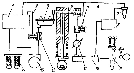
Fig. Diagrama sistemului de baterii al motorului diesel:
1 - rezervor de combustibil, 2 - linie de combustibil by-pass, 3 - filtre de combustibil fin, 4 - pompă; 5, 12 - supape de by-pass, 6 - linia de combustibil by-pass; 7 - injector controlat hidraulic, 8 - distribuitor special, 5 - injector controlat mecanic; 10 - capacitate, 11 - manometru; 13 - pompă de rapel, 14 - filtre grosiere
Carburant din rezervorul de carburant 1 prin filtrul 14 curge în cavitatea de aspirare a prafului grosier 13. Apoi combustibilul pompa de alimentare prin supapa de derivație 12 și filtrul Hepa 3 este injectat în pompa de înaltă presiune. În această parte a combustibilului este drenat prin conducta de combustibil de preaplin în rezervor 1. Pompa creează un recipient sub presiune 10, sprijinit de o supapă de preaplin automată 5 și controlată de presiunea manometrică 11. Presiunea din acumulator este controlată prin schimbarea arcului de supapă 5. strângere de combustibil în exces este returnat prin conducta de combustibil derivație 6 la rezervor. Combustibil din acumulatorul într-o cameră de ardere a unui motor diesel poate fi furnizată în trei moduri: printr-un injector acționat mecanic, printr-un distribuitor special și o duză cu acționare electromagnetică.
Cu un injector 9 controlat mecanic, combustibilul curge în injector direct din rezervorul de stocare. aprovizionare Faza și cantitatea de injecție de combustibil, în acest caz depinde de timpul și durata deschiderii acului duzei. Această metodă de furnizare a combustibilului într-o cameră de ardere a unui motor diesel, în prezent, este relativ rară în rezultatul unui complex de antrenare a acului supapei și performanța duzei nefiabile. La presiuni ridicate ale combustibilului, este dificilă sigilarea acului mobil la ieșirea din carcasă. Chiar și o bună etanșare într-un timp relativ scurt își pierde în mod semnificativ etanșeitatea, ducând la ruperea duzelor.
Când motorul diesel este setat duză controlat hidraulic, între vasul de depozitare și a duzei 7, în acest caz, sunt asamblate ventil 8, constând dintr-un bloc de supape de control sau a bobinelor. Faza și durata injecției este stabilită în funcție de modul motorului diesel prin intermediul unei supape de distribuție controlată de un organism special, sau prin intermediul bobinei de comandă. Introducerea unui sistem de comutare special în sistem complică atât sistemul cât și funcționarea acestuia.
Sistemul de alimentare cu combustibil al acumulatorului poate fi mult simplificat la instalarea injectorului electromagnetic.
Circuit de sistem de baterii Considerat cu baterie de mare capacitate este agențiile de complexe și nesigure de închidere și de distribuție, sub presiune ridicată, care crește costul sistemului și complicând întreținerea acestuia. Dorința de a elimina acest neajuns a dus la crearea unui sistem de baterii de capacitate mică, în care o singură injecție se realizează prin energia acumulată în secțiunea pompei sau duza.
Atunci când se utilizează o baterie de capacitate mare, în fiecare secțiune sunt prevăzute două pistoane: o dozare și o injecție. Pistonul de măsurare, ca și pistonul sistemului de injecție directă, alimentează și îl pompează într-o baterie specială. Pistonul de injecție deplasează combustibilul din baterie în injector și apoi în camera de ardere când se deschide valva de bypass sau deschiderea. Pistonul de injecție poate fi încărcat cu combustibil, aer, arc sau combustibil și cu un arc, aer și un arc. În concordanță cu aceasta, sistemele cu stocare de combustibil în pompă sunt împărțite în sisteme cu acționare hidraulică, aer, arc sau combinată.
Într-un sistem de baterii cu capacitate mică cu stocare de energie în volumul injectorului, doza de combustibil măsurată în mod obișnuit este introdusă în injector și comprimată acolo. La momentul injectării, volumul injectorului este descărcat și combustibilul este alimentat în camera de combustie a motorului diesel datorită energiei acumulate.
Sistemele de tip "baterie" permit asigurarea unei presiuni înalte a alimentării cu combustibil a camerei de combustie a motorului diesel la arborele cotit cu viteză redusă și vitezele de alimentare. Acesta este avantajul lor principal față de alte sisteme. Acestea asigură presiuni medii ridicate de injectare și facilitează lupta împotriva injectărilor repetate nedorite. În sistemele de combustibil cu acumulatori de înaltă capacitate, pompele de combustibil de înaltă presiune sunt mai simple în comparație cu pompele din sistemele cu acțiune directă. Numărul de pistoane de lucru ale acestor pompe nu este legat de numărul de butelii și poate fi redus chiar la unul. Alimentarea cu combustibil a pistoanelor nu este conectată în faze la procesul de lucru al motorului diesel, deci nu este reglat. Difuzarea pe scară largă a acestor sisteme este împiedicată de o mai mare complexitate decât sistemele directe.
Sistem de combustibil diesel destinat pentru plasarea, tratament în timp util și alimentarea cu combustibil la cilindrii motorului în cantitatea dorită și sub o presiune suficientă pentru toate modurile de funcționare la orice temperatură ambiantă.
Combustibilul diesel este unul dintre produsele rafinării petrolului. Conține diferite hidrocarburi (parafine, naftene, aromatice, etc.). Numărul atomilor de carbon care intră în moleculele de motorină atinge treizeci. Principala calitate a motorinei este ușurința de aprindere atunci când este în contact cu aerul fierbinte.
Inflamabilitatea unui combustibil este caracterizată de un număr cetanic. Cu cât este mai mare acest număr, cu atât este mai puțin rezistent la oxidarea moleculei de combustibil și este mai ușor să se aprindă. Combustibilul diesel cetanic este de 40 - 50 (cel mai adesea 45).
O caracteristică importantă a combustibilului este și viscozitatea la temperaturi diferite. Pentru a asigura funcționarea normală a motorului, combustibilul nu trebuie să înghețe la temperaturi scăzute (până la -60 ° C). În plus, este necesar ca combustibilul nu era toxic, au proprietăți anticorozive și de ungere, și nu creează abur în tubul de combustibil la temperaturi de până la 50 ° C
Pentru autotractor diesel, combustibilul este A (arctic), 3 (iarna) și L (vară). Cel mai utilizat combustibil este gradul 3 (la o temperatură negativă a aerului) și A (la temperaturi de peste 0 ° C).
Următoarele cerințe de bază sunt impuse tuturor unităților și componentelor sistemului de alimentare:
- impermeabilitate
- greutatea și dimensiunile ușoare
- încredere
- rezistență la coroziune
- rezistență hidraulică mică
- ușura
- cost redus de întreținere
Sistemul de alimentare cu combustibil și a ansamblurilor de combustibil trebuie să fie aranjate într-un compartiment de autovehicul, astfel încât atunci când defect combustibil picură nu este incidență pe părți având o temperatură care poate provoca aprinderea acestuia.
Schema sistemului de alimentare cu combustibil pentru un motor diesel puternic este prezentată în figură. În general, sistemul de alimentare cu combustibil include componente situate în afara motorului (pe cadrul sau în caroseria mașinii) și pe motor. Primele includ rezervoarele de combustibil ale rezervorului de colectare a combustibilului 7, pompa de combustibil de pre-combustibil 10, supapa de distribuție a combustibilului 77, conductele de combustibil de joasă presiune și alte unități. Al doilea include în principal pompa principală de alimentare cu combustibil 8, o pompă de combustibil de înaltă presiune (pompa de injecție HP) 5, injectori 4 și conducte de combustibil de presiune ridicată.
Când motorul funcționează, combustibilul din rezervoarele de combustibil este preluat de pompa principală de alimentare cu combustibil și la o presiune de 0,05 ... 0,1 MPa este furnizată pompei de injecție. Pe drumul de la rezervoare la pompă, combustibilul trece prin supapa de distribuție a carburantului, pompa de carburant și filtrul grosier 9. Dacă există un singur rezervor de combustibil instalat pe vehicul sau mai multe rezervoare care comunică între ele, supapa de distribuție a carburantului nu este disponibilă.
Înainte de a intra în pompa de carburant de la pompă, combustibilul este curățat de cele mai mici impurități din filtrul fin 3. secțiunea Pompă de injecție acționată de arborele cotit al motorului, în anumite puncte, în conformitate cu un ciclu de lucru și ordinea de funcționare a motorului alimentat de combustibil la presiune ridicată (50 MPa sau mai mare), în cantitatea necesară pentru injectoare. Prin injectoarele înșurubate în capul cilindrului, combustibilul este injectat în camerele de combustie în momentele în care cursa de compresie se termină în cilindri.
Fig. Schema sistemului de alimentare cu combustibil pentru un motor diesel puternic:
1 - rezervoare de combustibil; 2 - craniul pentru eliberarea aerului; 3 - filtru fin; 4 - injectoare; 5 pompe de injecție; 6 - motorul; 7 - un rezervor pentru colectarea combustibilului; 8 - pompa principală de alimentare cu combustibil; 9 - filtru grosier; 10 - pompă de alimentare cu combustibil înainte de pornire; 11 - supapa de distribuție a carburantului; conductele de combustibil sunt indicate printr-o linie solidă; conductele pentru eliminarea aerului din sistem sunt indicate prin linii punctate
Înainte de pornirea motorului, umplerea sistemului cu combustibil și alimentarea cu pompa de injecție se efectuează cu ajutorul unei pompe de combustibil de pre-combustibil. După pornire, această pompă nu funcționează.
Dacă se injectează aer în pompa de înaltă presiune și țevile de înaltă presiune care le conectează la injectoare, alimentarea cu combustibil a cilindrilor este încălcată. În consecință, funcționarea normală a motorului este de asemenea perturbată. Pentru a împiedica intrarea aerului în pompa de combustibil în traseul combustibilului, în el se află un bazin de aer situat la cel mai înalt punct al sistemului.
De obicei, butelia de aer este plasată în capacul filtrului filtrului fin. Înainte de pornirea motorului, dacă este necesar, aerul acumulat în vozduhootstoynike evacuate în aer cavitățile rezervorului de carburant 1 prin supapă (ventilul) 2 pentru eliberarea aerului. Pentru a face acest lucru, când motorul nu funcționează, supapa (supapa) este deschisă și sistemul este pompat prin pompa de pornire.
În acest caz, combustibilul deplasează aerul din butelia de aer în cavitatea de aer a rezervorului de combustibil prin supapa de distribuție a carburantului (așa cum se arată în figură) sau direct.
Combustibilul scurs în duza între ac și atomizorul este îndepărtat prin conducta de scurgere într-un rezervor special 7 sau în oricare din rezervorul principal de combustibil.
Rezervoarele de combustibil servesc la depozitarea combustibilului. Acestea pot avea o configurație diferită și o capacitate diferită, în funcție de designul vehiculului specific. Capacitatea totală a rezervoarelor de combustibil este determinată de domeniul de funcționare al vehiculului (de regulă nu mai puțin de 500 km). Majoritatea rezervoarelor sunt fabricate din tablă de oțel sau plastic de înaltă rezistență, rezistente la acțiunea combustibilului reactiv.
Pentru a preveni coroziunea rezervoarelor de oțel acoperite cu suprafață internă lac bachelita zinc sau ludyat. Pentru a crește rigiditatea cutiilor pe pereții lor, uneori perforate jgheab, iar în interiorul partițiile set non-continue, care, în plus, reduce suprafața liberă a combustibilului și afectează mișcarea acestuia vehiculului kolebaniyabqvremya.
Rezervoarele de alimentare cu combustibil sunt de obicei furnizate cu filtre de ecran. În partea inferioară a rezervoarelor se află rezervoarele de decantare. În cazul în care rezervorul are o capacitate mare, deversarea de combustibil prin gaura cu un dop și o supapă cu bilă situată deasupra băii. În acest caz, se utilizează un tub special cu furtun.
rezervoare spațiului aerian în legătură cu atmosfera prin tubul de drenaj sau alte dispozitive speciale care ar trebui să împiedice pătrunderea focului în cavitatea interioară a rezervorului și de combustibil de la deversând în timpul împingerile TS bruște, și (dacă este posibil) pentru a furniza aer curat care intră în rezervoare.
Pentru a măsura cantitatea de combustibil din rezervoarele utilizate pentru a măsura tijele. În prezent, în acest scop, cel mai des utilizate electric float senzori tip, trimiterea unui semnal electric proporțional cu nivelul de combustibil la un indicator corespunzător de pe panoul de instrumente TC.
Pompa principală de alimentare cu combustibil asigură alimentarea neîntreruptă a combustibilului din rezervoare către pompa de injecție atunci când motorul funcționează. Acesta este, de obicei, condus de la cranked sau arborelui cu came motorului. Se poate utiliza și un motor electric autonom, alimentat de la generatorul vehiculului.
Utilizarea unității asigură un flux uniform de combustibil, indiferent de turația motorului și posibilitatea unei opriri de urgență a întregului sistem. Există diferite modele de pompe de alimentare cu combustibil. Ele pot fi angrenaje, pistoane sau rotative (tip placă). De regulă, se utilizează pompe și pompe rotative.
Piston pompă de amorsare constă dintr-un corp 5, un piston 7 cu arcul 6, elementul de împingere 10 cu rola 77, arcul 9 și tija 8 și supapele - admisie și de descărcare 4 1 cu arcuri. Puncherul cu pistonul se poate deplasa în sus și în jos. Mișcarea ascendentă are loc atunci când excentricul 72 este rotit, realizat integral cu arborele cu came al pompei de injecție; Deplasarea în jos este asigurată de arcurile 6 și 9.
Atunci când proeminența came evadarea din pistonul rolei urmăritor sub acțiunea unui arc b se deplasează în jos, forțând ulei, sub aceasta, în linia de refulare a pompei. În acest moment, supapa de evacuare este închisă și presiunea negativă de admisie sub acțiunea pistonului este deschisă și fluxurile de combustibil de la linia de intrare în camera de lucru a pompei.
Când se deplasează elementul de împingere și pistonul în sus supapa de admisie este închisă de către presiunea combustibilului și presiunea asupra dimpotrivă, acesta este deschis, iar combustibilul din camera pompei în camera inferioară sub pistonul. Astfel, injecția de combustibil are loc numai atunci când pistonul se deplasează în jos.
În cazul în care alimentarea cu combustibil către cilindrii motorului este redusă, în conducta de evacuare a pompei, și, prin urmare, pistonul în cavitatea sub presiunea crește. În acest caz, pistonul nu poate cădea chiar și sub acțiunea arcului 6, iar elementul de împingere și tija se deplasează într-o doară. Deoarece consumul de presiunea combustibilului din camera de presiune este coborâtă, iar pistonul, sub acțiunea arcului 6 din nou începe să se deplaseze în jos, permițând alimentarea cu combustibil.
 Fig. Diagramă a pompei de pompare a combustibilului pistonului: 1 - o supapă de descărcare; 2 - corpul pompei de pompare manuală a combustibilului; 3 - pistonul pompei de pompare manuală a combustibilului; 4 - supapa de admisie; 5 - carcasa pompei de alimentare cu combustibil; 6, 9 - izvoare; 7 - piston; 8 - stem; 10 - împingătorul; 11 - cilindrul; 12 - arbore cu came cu arbore cu came
 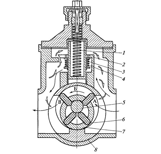 Fig. Schema pompei de alimentare cu combustibil rotativ:
 1 - arcul ventilului de reducere; 2 - supapa de reducere a presiunii; 3 - supapa bypass; 4 - arcul vanei de by-pass; 5 - degetul plutitor; 6 - placă; 7 - rotor; 8 - sticla ghidajului; A-B - camera pompei
Pompa de alimentare cu combustibil este, de obicei, combinată cu o pompă manuală de combustibil 2. Această pompă este instalată la intrarea în pompa principală de alimentare cu combustibil și este acționată manual prin deplasarea pistonului 3 cu tija.
Atunci când pistonul se deplasează în sus, se formează sub vid, se deschide supapa de admisie și de combustibil umple spațiul sub-plonjor. Atunci când pistonul se deplasează în jos supapa de admisie se închide, iar presiunea se deschide pentru a permite combustibilului să treacă mai departe de-a lungul liniei de combustibil.
În motoarele diesel puternice de mare viteză, se folosesc, în principal, pompe de pompare cu pompă rotativă. Rotorul 7 al pompei este acționat prin rotirea arborelui cotit al motorului. Rotorul are fante, care sunt inserate în placa 6. plăci One (exterior) de capăt aluneca pe suprafața interioară a duzei de ghidare 8, iar celălalt (interior) - circumferential degetul 5 plutitoare dispuse excentric în raport cu axa rotorului.
În același timp, aceștia sunt apoi mutați din rotor, apoi se deplasează în el. placă rotorului și împarte cavitatea interioară a duzei de ghidare pentru camera A, B și C, cantitatea de care rotorul este rotit în continuă schimbare. Un volum crește camerei, astfel încât se creează un vacuum în aceasta, sub acțiunea care combustibilul este aspirat din conducta de admisie.
Volumul scade camerale, presiunea crește în interiorul și combustibilul este deplasat în camera de presiune a pompei. Combustibilul din camera B trece de la intrarea la ieșirea din sticlă. Atunci când presiunea din camera de presiune la un anumit nivel numit Reductorul 2 presiunea, învingând forța arcului 7, iar combustibilul surplus este ocolit înapoi la intrarea în cavitatea pompei.
Prin urmare, o presiune constantă este menținută în cavitatea de injectare și conducta de evacuare. Înainte de a începe, atunci când motorul și, prin urmare, pompa principală de combustibil nu rulează, combustibilul poate fi pompat prin pompa de alimentare cu combustibil de pre-start. În acest caz, supapa de bypass 3 este deschisă învingând forța arcului 4. în poziția închisă a plăcii de supapă acoperă deschiderile Reductorul presiunii plăcii.
Înainte de pornirea motorului, sistemul de umplere combustibil și îi pune la pompa de combustibil se realizează prin pompa de transfer de prize 70. A fost anterior pompa de piston pe scară largă și o diafragmă (membrană) de la un manual tipuri de unitate.
În prezent, pompe cu palete rotative cu toate acestea, sunt utilizate din ce în ce sunt acționate de un motor electric alimentat de energia electrică a bateriei. Ele oferă un cost mai rapid de combustibil de pompare nu necesită energie musculară a conducătorului auto și poate fi utilizat într-o situație de urgență în cazul defectării pompei de transfer primar.
Purificarea combustibilului din impurități mecanice și apă are loc în filtre de purificare grosieră 9 și fină 3. filtru grosier instalat înaintea pompei principale de alimentare cu combustibil 8 oprește particule cu dimensiuni de 20 ... 50 m, care a reprezentat 80 ... 90% în greutate din toate impuritățile. Filtrul fin, amplasat între pompa principală de alimentare cu combustibil și pompa de injecție, amâne impuritățile de dimensiune de 2 ... 20 μm.
In prezent Propulsia cu motoare diesel utilizate următoarele tipuri de sitele: mesh, și slotul plăcii lentochno-.
În filtrele cu plasă, elementul de filtrare este o plasă de metal. Deoarece este posibil să se formeze cilindrii concentrici, care este forțat prin pereții secțiunii discoid înșirate pe un tub central cu deschideri în peretele de combustibil sau, conectate la conducta de evacuare.
Centura canelată filtreaza elementul de filtrare este o sticlă plisat înfășurat în jurul său profilat panglică. Prin fantele dintre spirele benzii formate datorită combustibilul proeminențele din spațiul din jurul elementului filtrant cade în jgheaburi între banda de sticlă ondulată, apoi - în cavitatea dintre fundul cupă și capacul, unde îndepărtat prin conducta de evacuare.
Elementul de filtrare al filtrului pentru placă este un cilindru tubular compus din discuri inelare, subțiri, cu proeminențe de îndoire. Datorită acestor proeminențe, discurile sunt formate între discuri. Combustibilul intră pe suprafețele exterioare și interioare ale cilindrului și, curățând prin fisurile dintre discuri. Combustibilul curățat prin orificiile de capăt ale discurilor este trimis în partea superioară a filtrului la priză.
Foarte adesea, filtrul grosier este combinat cu un rezervor pentru apă în motorină. În acest caz, este necesară oprirea periodică a dopului pentru evacuarea apei din acesta.
În filtre fine, cartușele de filtrare, cum ar fi "steluțele cu mai multe fascicule" sau pungile din carton și discurile din pâslă, sunt utilizate în mod obișnuit ca elemente de filtrare. Rareori aplicați cadre cu adsorbție a impurităților mecanice în ambalaj (de exemplu, vată minerală), cadre cu o țesătură sau înfășurări filetate etc.
În procesul de operare a filtrelor de combustibil TC sunt contaminate, ceea ce duce la o creștere a rezistenței acestora. Pentru a asigura că alimentarea cu combustibil a pompei de injecție nu sa oprit, filtrul grosier trebuie clătit periodic și elementul filtrant al filtrului fin trebuie înlocuit cu unul nou.
Pompa de combustibil de înaltă presiune 5 este proiectată să distribuie cu precizie combustibilul și să o alimenteze la injectoarele 4 la presiunea necesară și la un anumit timp. În in-line motoare o astfel de pompă este plasată pe partea laterală a motorului, pe jumătatea superioară a carterului său. La motoarele în formă de V se stabilește în dezordinea cilindrilor.
Există multe tipuri de pompe de injecție. În special, motoare diesel relativ scăzute concepute pentru autoturisme, de regulă, instalați o distribuție de tip pompă de injecție cu un singur piston-distribuitor de injecție. Cu toate acestea, diblurile puternice cu mai multe cilindri sunt cele mai multe ori echipate cu pompe cu piston multiplu. Un exemplu de astfel de pompă de înaltă presiune pentru un motor diesel cu șase cilindri diesel este prezentat în figură.
Pompa constă dintr-o carcasă 5 cu capace, șase secțiuni de pompă, un mecanism de acționare pentru secțiunile pompei și un mecanism de rotire a pistoanelor. Fiecare secțiune de pompare cuprinde pistonul 8, arcul de rapel 11 șaiba suport, supapa de refulare 3 din scaun, arcul și bontul, precum mamelonului 2 și celelalte elemente de fixare de susținere și ghidare.
Mecanismul de antrenare al secțiunilor pompei constă dintr-un arbore camă 7 și niște împingătoare cu role 6 cu șuruburi de reglare. Mecanismul de rotire a pistoanelor include bucșele rotative 10 cu jenti dintate și o bară de rafturi 9 cu bucșe și un șurub restrictiv. De-a lungul secțiunilor din corpul pompei, două canale longitudinale 1 și 4 sunt forate, conectate unele cu altele prin canale transversale. Fiecare piston este montat foarte precis pe manșonul său, ceea ce asigură o presiune ridicată cu cea mai mică scurgere a combustibilului prin goluri.
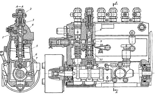 Fig. Pompă de combustibil de înaltă presiune: 1,4 - canale longitudinale; 2 - montare; 3 - supapa de livrare; 5 - carcasa pompei; 6 - împingătorul cu role; 7 - arborele cam; 8 - piston; 9 - rack; 10 - bucșa rotativă; 11 - arcul de întoarcere
 Pompa funcționează după cum urmează. Arborele cu came este rotit de către arborele cotit al motorului, prin intermediul unui tren de roți dințate (arbore cu came de viteză unghiulară de 2 ori a vitezei arborelui cotit mai puțin). Rotirea, arborele de camă își deplasează camele cu rolele de împingere 6, care ridică pistoanele în sus.
Calea de retur a împingătoarelor și a pistoanelor este asigurată de arcuri de revenire. La canalul 4, este alimentat combustibilul din pompa de alimentare cu combustibil, curățat anterior într-un filtru fin.
Când pistonul este în poziția inferioară, combustibilul de la canalul 4 intră în cavitatea supergănală rezultată. Când pistonul se deplasează în sus, orificiul de intrare este închis, iar combustibilul sub presiune înaltă trece prin supapa de presiune, îmbinarea și conducta de combustibil de înaltă presiune la injector.
Injectarea de combustibil are loc până când cavitatea supergănală este conectată la canalul de scurgere 1 prin canale axiale, radiale și șuruburi în piston. La constantă în timpul pistonului determină înălțimea proeminenței cu came, cantitatea de combustibil furnizată injectorului este reglată prin rotirea pistonului cu ajutorul cremalierei și manșonul rotativ cu coroana dințată.
O canelură spirală se formează în pistonul, astfel încât cel puțin o rotație schimbă distanța de la marginea orificiului de preaplin asociat cu canalul 7, muchia de închidere la marginea unui șanț elicoidal. Lungimea cursei pistonului în timpul căreia se injectează combustibilul se schimbă de asemenea.
Pentru ca carburantul furnizat cilindrilor de ritm ținute în timp util ars, iar motorul a dezvoltat cea mai mare putere, este necesară pentru creșterea vitezei motorului crește ușor unghiul de injecție de combustibil de sincronizare.
Reglarea acestui unghi pentru pompele cu control mecanic ambreiaj centrifugal special este prevăzut, care este instalat în carcasa pompei și este proporțională cu viteza de rotație a arborelui cotit dislocă un anumit unghi al arborelui pompei de came în direcția de rotație.
Mecanismul controlerului cu toate regulatoarele este conectat la pompa de injecție. Sprijină automat viteza motorului specificată de șofer, stabilește frecvența minimă la ralanti și, de asemenea, limitează frecvența maximă. Mecanismul regulatorului este un sistem de legături, arcuri și opriri legate de suportul pompei de injecție a cărui mișcare depinde de viteza arborelui cu came.
Duza servește la alimentarea cu combustibil a cilindrului de motor sub presiune înaltă într-o formă fin dispersată.
Un injector tipic cuprinde o carcasă 5 cu un pulverizator 3, ghidul știftul 4 și piulița 2, un nebulizator 1 ac cu b tijă, un arc 7 cu o șaibă de susținere, șurubul de reglare 9 și manșonul 8, piulița capacului 10 și mamelonul toplivopriemny 12 cu un filtru de 11 Atomizatorul și acul trebuie ajustate foarte precis una de cealaltă.
În partea superioară există un inel de pulverizator și mai multe (de obicei trei) a canalului de combustibil vertical, iar în partea de jos - centrale conductele de admisie și de evacuare, cu orificii de pulverizare. Diametrul acestor găuri este de 0,2 ... 0,4 mm. Acul închide canalul de ieșire cu capătul său conic inferior.
Pulverizatorul este fixat strâns la corpul injectorului cu ajutorul unei piulițe de legătură. Canalul de combustibil al corpului este conectat la canalul inelar al atomizorului prin canalele sale verticale. Poziția corectă a pistolului de pulverizare în raport cu carcasa este asigurată de știftul de ghidare.
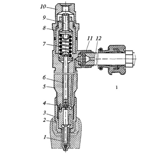 Fig. duza:
 1 - acul nebulizatorului; 2 - piuliță de legătură; 3 - nebulizator; 4 - un știft de direcționare; 5 - corpul injectorului; 6 - stem; 7 - un izvor; 8 - bucșa; 9 - șurubul de reglare; 10 - piuliță cu capac; 11 - filtru de plasă; 12 - o priză de alimentare cu combustibil
Combustibilul furnizat duza prin montarea toplivopriemnomu trece prin sita si canalul de combustibil al corpului pistolului de pulverizare wverhney acesta intră în cavitatea inelară. La atingerea presiunii dorite în cavitatea care acționează, printre altele, pe ac conic centură se ridică în sus împotriva rezistenței arcului. În acest moment, canalul de ieșire este deschis și combustibil prin acesta, iar orificiile de pulverizare în cilindrul motorului intră în camera de ardere.
După terminarea secțiunii pompei de alimentare cu carburant și căderea de presiune a pompei peste ac stă în scaunul său, oprirea injecției de combustibil. combustibil Scurgerea scurs prin în partea superioară a duzei și prin orificiile din șurubul 9 și piulița 10 pe o conductă specială 7 fuzionează în rezervorul de colectare a combustibilului.
Cerințe stricte moderne la nivelul emisiilor de substanțe nocive de către motoare ardere internă designerii diesel forțați să caute noi soluții în domeniul echipamente de combustibil pentru ei. Faptul este că, chiar și pompa cea mai perfectă nu poate oferi o astfel de presiune a combustibilului la care s-ar fi pulverizat atât de fin încât ar putea arde complet în camera de ardere.
rezultate incomplete de ardere într-un consum mai mare de combustibil, și cel mai important - o creștere a concentrației de gaze de evacuare de substanțe nocive, în special negru de fum. Prin urmare, în prezent pentru motoarele diesel cu injecție directă se utilizează din ce în ce așa-numita baterie de alimentare cu combustibil sistem.
Diferența principală a acestui sistem de „clasic“ este disponibilitatea de common rail (acumulator de presiune), în care în timpul funcționării creează o presiune foarte mare.
feroviar de combustibil conectat la conductele de înaltă presiune, cu injectoare controlate electronic, ace sunt deplasate de către electromagnet pe baza semnalelor de la un calculator de control al motorului (modulul electronic). Un astfel de sistem de alimentare cu combustibil face posibilă optimizarea performanțelor motorului în aproape toți parametrii.
LUCRAREA LABORATORULUI № 7
Tema: "Scopul, dispozitivul și principiul de funcționare a sistemului de putere al motorului diesel"
Scopul muncii: studiul scopului, dispozitivului și principiului de funcționare a sistemului de putere al motorului diesel.
Dispoziții generale
Cerințe de bază .Sistema motoare diesel de putere ar trebui să creeze injecție de combustibil de presiune ridicată într-un cilindru, porțiuni dozate de combustibil în funcție de sarcina motorului diesel pentru a începe injectarea combustibilului în camera de ardere la un moment dat, pentru o perioadă predeterminată de timp și cu o anumită intensitate, împrăștierii bun și uniform distribuie combustibilul în volum combustor, pentru a asigura pornirea injecției și pompa alimentat porțiunea de combustibil, identic în toți cilindrii, combustibilul este în siguranță se filtrează, înainte de intrarea acestuia în pompă și duze.
Aceste cerințe se datorează faptului că procesul de amestecare într-un motor diesel este dat un timp foarte scurt (de ordinul 0,001 s), deci este important să pulveriza combustibilul în picături mici și să le distribuie în întregul volum de aer în camera de ardere.
Aparate de alimentare cu energie electrică la motoare diesel
Filtru de combustibil fineste amplasat pe linia de combustibil din fața pompei de combustibil sau a pompei de injecție. Filtrarea are loc datorită fluxului de combustibil prin elementele de filtru 3 (Figura 6.1), realizate din materiale presate sau microfibre sintetice multistrat. Există, de asemenea, modele care constau în două filtre conectate fie în paralel pentru a crește capacitatea, fie în serie, ceea ce permite efectuarea unei purificări pas cu pas a combustibilului sau combinarea filtrelor grosiere și fine într-o singură unitate. Se folosesc tot mai multe construcții de filtrare, în care se modifică numai elementul de filtrare.
Fig. 6.1. Filtru de combustibil fin:
1 - alimentarea cu combustibil; 2 - evacuarea combustibilului rafinat;
3 - element filtrant; 4 - ștecher; 5 - acoperire;
6 - cazul; 7 - distanțier; 8 - colector de apă
Combustibilul poate conține umiditate sub formă de picături de apă sau sub formă de emulsie de apă cu combustibil (de exemplu, condensul rezultat din diferențele de temperatură din rezervorul de combustibil). În mod normal, apa nu trebuie să intre în sistemul de injecție a combustibilului.
Datorită diferitelor tensiuni de suprafață ale apei și combustibilului, picăturile de apă se formează pe elementele de filtrare. Ele se acumulează în antetul 8. Se poate folosi un separator separator separator pentru a elimina umezeala liberă, în care picăturile de apă sunt separate de combustibil prin forța centrifugală. Controlați prezența senzorilor speciali de apă.
Pentru a preveni înfundarea porilor elementelor de filtrare cu cristale de parafină formate în combustibil în timpul funcționării în timpul iernii, în filtrele de combustibil se utilizează preîncălzirea combustibilului. În majoritatea cazurilor, preîncălzirea combustibilului se realizează cu ajutorul elementelor electrice de încălzire, a lichidului de răcire sau a combustibilului provenind din sistemul de retur.
Pompă de combustibil de înaltă presiune.Un exemplu de pompă de combustibil de înaltă presiune înaltă utilizată la autoturisme este pompa diesel Mercedes 190, care constă din mai multe secțiuni identice (figura 6.2). La partea frontală a acestei pompe este o pompă de vid 14 acționată de un excentric 2 situat la capătul arborelui camă.
Fig. 6.2. Pompa de combustibil a unei mașini de înaltă presiune Mercedes:
1 - priza de conectare a amplificatorului de vid al frânelor; 2 - acționarea excentrică a pompei de vid; 3 - un lanț de asterisc; 4 - cuplaj automat de sincronizare;
5 - șurubul de instalare a începutului injectării; 6 - alimentarea cu combustibil; 7 - conducte de înaltă presiune;
8 - pârghia de suprapunere a dăruirii de combustibil; 9 - camera de vid a opritorului motorului; 10 - camera de vid de creștere a frecvenței de rotație a unui arbore cotit; 11 - regulatorul frecvenței de rotație;
12 - o priză pentru instalarea adaptării la începutul injectării; 13 - pompă de alimentare cu combustibil; 14 - pompa de vid
În partea inferioară a carcasei pompei un ax cu came, care este conectat la roata de antrenare prin intermediul unui cuplaj vpryska.Na arborelui avansând cu came sunt profilate cu came pentru fiecare secțiune de pompare și o camă pentru acționarea pompei de joasă presiune, care este atașat la planul de împerechere al pompei de înaltă presiune.
Vedere generală a liniei in-line Injecție pompa cu controlat electronic este prezentat în Fig. 6.3.
Ca și în pompa de injecție linie convențională, echipat cu un regulator mecanic, cantitatea de injecție de combustibil este o funcție de control a poziției de alimentare cu combustibil șina 3 și pompa de viteză a arborelui de antrenare. Rack-ul este controlat cu ajutorul unui regulator special pentru cantitatea de combustibil electromagnetic 8 conectat direct la pompa de injecție. Regulatorul electromagnetic este alcătuit dintr-o bobină și un miez care acționează pe șina pompei de injecție. Poziția șinei de pompare este determinată de senzorul de poziție inductiv al șinei 9 fixat pe el. Regulatorul de bobină electromagnetică, în funcție de semnalele de intrare ale senzorului de temperatură a motorului, axul pompei de control al vitezei de rotație a pedalei de șină etc. Excitația de curent diferită magnitudine este furnizată de unitatea de comandă. În acest caz, miezul regulator, fiind tras de actele de camp magnetic de pe pompa feroviară împotriva forței arcului prin modificarea cantității de combustibil injectat. Odată cu creșterea curentului furnizat de unitatea de comandă, miezul, care este retras cu o cantitate mare și acționează asupra șinei, mărește alimentarea cu combustibil. Atunci când solenoidul este deconectat, arcul apasă șina în poziția de oprire a motorului și oprește alimentarea cu combustibil.
Discul dințat 11 este montat pe arborele cu came al pompei de înaltă presiune, care, la rotire, furnizează impulsuri la traductorul de măsurare inductiv. Unitatea de comandă electronică utilizează intervale de impulsuri pentru a calcula turația motorului.
Fig. 6.3. Seria pompa de combustibil cu control electronic:
1 - manșon; 2 - manșon de control; 3 - șină de alimentare cu combustibil; 4 -plunzher; 5 - un arbore cam; 6 - supapa electromagnetică a începutului de a da combustibil; 7 - un ax de gestionare a fișei de reglare; 8 - regulatorul electromagnetic al cantității de combustibil; 9 - senzor de poziție rack inductiv; 10 - conexiune furcă; 11 - discul; 12 - pompă de alimentare cu combustibil
Furnizarea de combustibil pentru injectori nu este fundamental diferită de pompă de injecție mecanică. Cu toate acestea, nu există niciun moment de injectare în pompele controlate electronic, iar temporizarea injecției este controlată de semnalele furnizate de unitatea de comandă la supapa solenoidului de pornire a alimentării cu combustibil. În funcție de amplitudinea curentului furnizată bobinei electrovalvei pornește alimentarea cu combustibil 6 (fig. 6.3), un miez de presiune a arcului, este atras în bobina cu o anumită valoare, rotirea arborelui de comandă 7, manșonul de reglare. La rândul său, arborele de comandă este conectat la manșonul de comandă. Când arborele este rotit, manșonul de comandă poate fi ridicat sau coborât. Când supapa solenoidului este deconectată, acțiunea arborelui sub arc transferă bucșele în poziția superioară (injecție târzie).
Punerea în mișcare poate fi reglată prin schimbarea poziției bucșelor la 40 ° față de rotația arborelui cotit.
 Principiul de funcționare a pieselor de precizie ale mantalei, plonjorului și manșonului de comandă este prezentat în Fig. 6.4.
Fig. 6.4. Principiul de funcționare a perechii de piston cu manșonul de comandă:
a - НМТ плунжера; b - pornirea alimentării cu combustibil; c - finalizarea alimentării cu combustibil; d - TDC a pistonului; h1 - mișcare preliminară; h2 - mișcare utilă; h3 - ralanti; 1 - supapa de livrare;
2 - o cavitate de presiune ridicată; 3 - un dop al pistonului; 4 - manșon de control; 5 - canelura elicoidală a pistonului; 6 - o deschidere de distribuție în piston; 7 - piston; 8 - arcul pistonului; 9 - împingătorul cu role; 10 - cama; 11 - deschidere de descărcare; 12 - cameră cu presiune scăzută
Piston de pe lângă porțiunea schimbarea uluc elicoidal convențional alimentat la injectoare 6 are un orificiu de distribuție care poate fi deschis sau închis de către manșonul de comandă 4. Atunci când pistonul se deplasează în jos combustibilul intră în camera de piston.
Când mișcarea pistonului 7 în sus, atâta timp cât orificiul de debitare 6 situată în cavitatea unei camere de aspirație de joasă presiune 12, presiunea din camera de presiune 2 este aliniată cu presiunea din camera de aspirație printr-un canal central (fig. 6.4, a).
Odată ce orificiul de distribuție 6 este suprapus de control al marginii de piston manșon 4 camera de înaltă presiune și decuplarea cavității de aspirație (fig. 6.4, b) și presiunea din camera de presiune începe să se ridice. După ce supapa de descărcare 1 se deschide sub presiune înaltă, presiunea în conducta de înaltă presiune crește până la dimensiunea deschiderii acului injectorului (începutul injectării).
Injectarea continuă în timpul deplasării tijei până la marginea canalului elicoidal 5 nu va ajunge la orificiul de evacuare 11 (fig. 6.4, s), în manșonul de control 4. După aceea, presiunea din cavitățile aliniate, iar supapa de evacuare 1 cu arc și presiunea combustibilului este închisă.
Reglarea începerii injectării combustibilului depinde de viteza arborelui cotit, de încărcarea motorului și de temperatura acestuia. Începerea injecției de combustibil depinde de poziția manșonului de comandă situat în locașul inelar al manșonului. Schimbarea la începutul injectării are loc simultan în toate secțiunile pompei prin ridicarea sau coborârea manșoanelor de control. Pornind de injecție de carburant depinde de poziția bucșei de comandă, deoarece injecția poate avea loc numai după acoperirea orificiului de distribuire a pistonului 6, altfel combustibilul printr-o conductă ascendentă 6 și gaura va fi deplasată de către cavitatea 12 și presiunea din camera de pompare nu va crește. La momentul de suprapunere 6 găuri cavitate în camera pompei devine sigilată și presiunea carburantului începe să crească brusc, deschizând astfel supapa de refulare. Dacă bucșa este relativă față de deschiderea pistonului 6 de mai sus, injecția începe mai târziu, deoarece fereastra pistonului se va suprapune mai târziu. La o poziție inferioară a bucșei în raport cu fereastra pistonului, suprapunerea ferestrei pistonului va fi mai devreme și injecția va începe mai devreme. Cursa bucșei este de aproximativ 5,5 mm când unghiul de avans al injecției de combustibil de 12 ° este modificat de unghiul de rotație al arborelui cotit.
Reglarea cantității de combustibil furnizatse efectuează ca în cazul pompelor mecanice convenționale de injecție a combustibilului, prin rotirea pistonului 7, pe care este conectat deschiderea de distribuție 6 la canelura de șurub 5 a pistonului. Dacă pistonul este rotit cu un unghi mic, cantitatea furnizarea de combustibil este mică, deoarece canelura elicoidală rapid după închiderea deschiderii de distribuire în pistonul manșonul de comandă 6 ajunge la orificiul de evacuare 11 a manșonului. Cu o întoarcere mai mare a pistonului, alimentarea cu combustibil crește corespunzător.
Oprirea alimentării cu combustibil Când motorul este oprit. În acest caz, pistonul este așezat într-o astfel de poziție încât în orice poziție dintre punctele moarte ale cavităților de aspirație și evacuare sunt conectate prin deschiderea centrală a pistonului.
Se efectuează un avans al momentului injectării combustibilului (începutul alimentării cu combustibil) cuplaj automat de sincronizare prin injecție în funcție de viteza arborelui cotit. Se compune din două semicuple - conducător 1 și 2 conduse (figura 6.5). Ambele jumătăți de cuplare sunt conectate mobil unul față de celălalt printr-un element excentric 5 care constă în compensarea și reglarea excentricilor care sunt ghidate de un bolț rigid conectat la carcasă. Cuplajul intern este conectat rigid la arborele camă al pompei de înaltă presiune. Motorul pompei de injecție (pinionul, pinionul) este atașat la jumătatea exterioară a cuplajului. În interiorul ambreiajului de avansare a injecției există greutăți centrifugale 8 care sunt conectate la elementele excentrice 5 și sunt menținute în poziția inițială prin arcuri cu rigiditate variabilă 7.
Principiul de funcționare al cuplajului este prezentat în Fig. 6.6. La o viteză mică de rotație a arborelui cotit al motorului, sarcini centrifugale sunt comprimate de forțele arcurilor de blocare, conducerea și partea de cuplare acționat au unghi de divergență (Fig. 6.6, a). Pe măsură ce frecvența de rotație a arborelui cotit crește, forțele centrifuge care acționează asupra sarcinilor cresc. Sub acțiunea acestor forțe, contracararea izvoarelor este depășită și sarcinile divergente (fig.6.6, c, c).
 Fig. 6.5. Injectarea temporizării:
1 - cuplajul semi-conducător (mecanismul de acționare); 2 - cuplaj intermediar (hub); 3 - carcasa ambreiajului; 4 - ajustarea excentrică; 5 - excentric suplimentar; 6 deget; 7 - un izvor;
8 - mărfuri; 9 - șaibă de sprijin
Loturile care acționează pe elementul excentric este rotit jumătate de ambreiaj acționat asociat cu arborele cu came printr-un anumit unghi, ceea ce are ca rezultat o deplasare unghiulară a arborelui cu came al pompei (direcția de rotație) în raport cu unitatea de pompare. În consecință, unghiul de avans al injecției de combustibil crește (Figura 6.6, d).
Fig. 6.6. Principiul de funcționare a cuplajului de avansare a injecției de combustibil
Prin reducerea vitezei de rotație a arborelui cotit scade sarcinile forței centrifuge și cu ajutorul unor arcuri acționate pivoți de cuplare jumătate față de lider în direcția opusă rotației arborelui cu came al pompei, prin care se reduce unghiul de injecție de temporizare.
Sisteme de combustibil cu injectoare de pompare
Sisteme de echipamente diesel pentru combustibil ale pompei-injector au fost aplicate pe camioane începând cu anul 1994 și a autoturismelor din 1998. Modulul modular de proiectare a sistemelor de alimentare pentru motoarele diesel cu injectoare de pompă vă permite să instalați fără prea mult timp motoare de diverse modele.
Dezavantajul injectoarelor de pompare este o creștere a înălțimii capului cilindrului, care la rândul său determină o creștere a înălțimii motorului.
Injectoarele cu pompă constau din trei subsisteme: alimentarea cu combustibil de joasă presiune, alimentarea cu combustibil la înaltă presiune, alimentarea cu aer și evacuarea gazelor de eșapament.
Subsistemul de alimentare cu combustibil la presiune joasă este necesar pentru alimentarea cu combustibil a pompei de înaltă presiune și pentru curățarea combustibilului.
Subsistemul de alimentare cu combustibil de înaltă presiune servește la crearea unei presiuni înalte de injecție a combustibilului în camera de ardere.
Subsistemul de alimentare cu aer și gaze de evacuare include dispozitive pentru curățarea aerului care intră în buteliile motorului și pentru curățarea gazelor de eșapament după ce acestea sunt scoase din cilindri.
Principalele componente ale sistemului de alimentare cu motor cu injectori de pompă sunt prezentate în figura 6.7.
Amplasat în rezervor, pompa de combustibil electric 15 pompează carburantul către filtru. Supapa de reținere 12 împiedică descărcarea combustibilului de la distribuitorul 7 și conducta de joasă presiune 14 în rezervor după oprirea motorului.
Pompa de alimentare cu combustibil 10 servește la colectarea combustibilului din filtru și la alimentarea acestuia sub presiune crescută la injectoarele pompei. Supapa de reducere a presiunii 11 menține presiunea combustibilului furnizat injectorului injectorului în intervalul de 8,5 kgf / cm2. Supapa de limitare 5 menține presiunea combustibilului în linia de scurgere la nivelul de 1 kgf / cm2, reducând astfel pulsațiile de presiune din sistem.
Datorită presiunii ridicate de injecție în sistemele de combustibil ale automobilelor diesel cu injectoare, iar în unele sisteme CommonRail, combustibilul este încălzit într-o asemenea măsură încât, pentru a preveni deteriorarea rezervorului de carburant și senzorul de nivel de combustibil trebuie să fie răcit înainte de a fi returnat la rezervor. Combustibilul care revine de la injectoare trece prin răcitorul 3, dând căldură în circuitul de răcire. Senzorul de temperatură a carburantului 4 generează un semnal către unitatea de comandă a motorului.
Din filtru, combustibilul este alimentat la conducta de alimentare din capul unității. În conducta de alimentare, combustibilul trece prin pereții interiori ai distribuitorului de combustibil 7 în direcția primului cilindru. Prin găurile din pereți, combustibilul este alimentat în cavitatea inelară dintre distribuitor și pereții capului de bloc.
Fig. 6.7. Sistem de alimentare cu motor diesel cu injectoare de pompare:
1 - rezervor de combustibil; 2 - conducta de combustibil la încălzitorul auxiliar; 3 - răcitor de combustibil; 4 - senzor de temperatură a combustibilului; 5 - supapa de limitare din linia de scurgere;
6 - țeavă de scurgere; 7 - distribuitor de combustibil; 8 - conducte de înaltă presiune;
9 - pompă injector; 10 - pompă de alimentare cu combustibil; 11 - supapa de reducere a presiunii din conducta de alimentare cu combustibil; 12 - supapa de reținere; 13 - filtru de combustibil; 14 - conducte de joasă presiune; 15 - pompa de alimentare cu combustibil
Aici, combustibilul este amestecat cu combustibilul încălzit, care este presat de injectorii pompei în conducta de alimentare. Din această cauză, se atinge aceeași temperatură și, prin urmare, aceeași cantitate de combustibil ajunge la toate injectoarele de pompă, ceea ce asigură o funcționare uniformă a motorului. Fără distribuitor, combustibilul ar circula inegal în pompa injectorului. Combustibilul încălzit, presat de la injectoarele pompei în conducta de alimentare, ar fi avansat de către combustibilul de intrare din al patrulea cilindru în direcția primului cilindru. Din această cauză, temperatura combustibilului ar crește de la cel de-al patrulea cilindru până la primul și o cantitate diferită de combustibil va curge la injectoarele pompei. Consecința acestui fapt ar fi o funcționare inegală a motorului și o temperatură prea ridicată în zona cilindrilor frontali.
Injectoarele. O imagine generală a sistemului de injecție "comonrail" firmă "Bosch" este prezentată în Fig. 6.8. Acesta este compus din electromagnetului 11 și armătura 10, o supapă de control minge mică 8, acul de închidere 2, atomizator 3, supapa de comandă a pistonului 5, un arc tijă 9. Robinetul sferic este presată pe scaunul supapei cu forța arcului și electromagnetul. Forța arcului este proiectat pentru presiuni de până la 100 kg / cm2, ceea ce este semnificativ mai mică decât presiunea în conducta de înaltă presiune (250 ... 1800 kg / cm2), astfel încât numai prin aplicarea unei forțe de minge supapă electromagnet nu va depărta de scaunul supapei, separarea bateriei de linia de scurgere. ajutaj de pulverizare a acului presat inoperant împotriva scaunului de nebulizatorul primăvară - acest lucru previne intrarea aerului în duză atunci când motorul este pornit.
Spre deosebire de benzină duze electromecanice din duze „kommonreyl“ electromagnet la o presiune de 1350 ... 1800 kgf / cm2 nu este capabil să ridice acul de închidere, se folosește principiul așa hydrostrengthening (fig. 6.9). Pozițiile din Fig. 6.9 corespund pozițiilor secțiunii duzei din figura 6.8.
Fig. 6.8. Tăierea arborelui electro-hidraulic Bosch:
1 - accelerația prizei; 2 - acul; 3 - nebulizator; 4 - un arc de blocare a acului; 5 - pistonul supapei de comandă; 6 - bucșa pistonului; 7 - accelerația de plumb; 8 - supapă de control cu bilă; 9 - stem; 10 - Ancora; 11 - electromagnet; 12 - un arc al supapei
Fig. 6.9. Principiul duzei electrohidraulice:
a - duza în stare închisă; b - duza în stare deschisă; c - faza de închidere a duzelor
La crearea presiunii în baterie, acționează atât pe suprafața conică a acului, cât și pe pistonul supapei de comandă 5 (Fig.6.9, a). Deoarece suprafața de lucru a pistonului 50% mai mult pătrat conic suprafață ac, un ac continuă să fie presat pe scaunul atomizorului.
Când tensiunea este furnizată de la unitatea de comandă la electromagnetul 11, tija tijei tijei 9 se ridică și se deschide supapa de comandă a balonului 8 (figura 6.9, b). Presiunea din camera de control 7 scade ca urmare a deschiderii deschizăturii de accelerație, iar combustibilul este trecut din zona de deasupra pistonului supapei de comandă în zona de scurgere. Presiunea pe pistonul supapei de comandă cade, deoarece orificiul de admisie a clapetei de admisie a supapei de comandă are o secțiune transversală mai mică decât supapa de descărcare. Acul de blocare 2 este apoi deschis sub presiune înaltă în buzunarul nebulizatorului 3. Suma Alimentarea cu combustibil depinde de timpul alimentarea cu tensiune a electromagnetului 11, și, prin urmare, timpul de control bilă deschiderea supapei de 8. La terminarea energizare a electromagnetului 11, armătura de arcul coboară, supapa de comandă bilă este închis, presiunea din camera de comandă este redus prin un jet special (Figura 6.9, c). Sub presiunea combustibilului, pistonul supapei de comandă 5 având un diametru mai mare decât diametrul acului este închis.