Motorul cu rachete de presiune (LRE) - un motor cu rachete chimice care utilizează lichide, inclusiv gaze lichefiate, ca combustibil pentru rachete. În ceea ce privește numărul de componente utilizate, motoarele cu rachete cu unul, doi și trei componente diferă.
Enciclopedic YouTube
1 / 5
CUM FUNCȚIONEAZĂ MOTORUL ROCKET? [LRE]
Propulsor rachetă cu motor RD-191
# 24 CUM SĂ FACEȚI UN MOTOR ROCKET
Cum sa faci un motor cu racheta pe zahar. Lansăm racheta. #olofly
Lichid RD-180: teste la banc | Combustibil lichid RD-180: test de incendiu
subtitrari
Istoria
Posibilitatea de a folosi lichide, inclusiv hidrogen lichid și oxigen, drept combustibil pentru rachete, a fost subliniată de K.E. Tsiolkovsky în articolul "Studiul spațiilor lumii cu instrumente de jet", publicat în 1903. Primul experiment experimental LRE a fost construit de către inventatorul american Robert Goddard în 1926. Proiecte asemănătoare în anii 1931-1933 au fost efectuate în URSS de un grup de entuziaști condus de F. A. Zander. Aceste lucrări au continuat în RNII organizat în 1933, dar în 1938 tema LPRE a fost închisă [ ], iar designerii de frunte S. P. Korolev și V. P. Glushko au fost reprimați ca "dăunători".
În prima jumătate a secolului al XX-lea, designerii germani Walter Thiel, Helmut Walter, Werner von Braun și alții au obținut cel mai mare succes în dezvoltarea LRE. În timpul celui de-al doilea război mondial, au creat un număr de LRE pentru rachetele militare: V-2 balistice, Schmetterling, Raintochter R3. În 1944, în cel de-al treilea Reich, o nouă ramură a industriei a fost creată de fapt - știința rachetelor, sub îndrumarea generală a V. Dornbergerîn timp ce în alte țări dezvoltarea LRE a fost într-o etapă experimentală.
După război, dezvoltarea designerilor germani a împins cercetarea în domeniul rachetei în URSS și în Statele Unite, unde au emigrat mulți cercetători și ingineri germani, inclusiv V. von Braun. Începutul cursei înarmărilor și rivalitatea dintre URSS și SUA pentru conducerea în explorarea spațială au fost stimulenți puternici pentru dezvoltarea LRE.
În 1957, în URSS, sub conducerea lui S. P. Korolev a fost creat ICBM R-7 echipat cu motorul de rachetă RD-107 și RD-108, la acel moment cel mai puternic și perfect din lume, dezvoltat sub conducerea lui V. P. Glushko. Această rachetă a fost folosită ca purtător al primelor sateliți de pământ artificial din lume, prima nava spațiale și sonde interplanetare.
În 1969, a fost lansată prima nava spațiale din seria Apollo în Statele Unite, lansată pe calea de zbor a Lunii de vehiculul de lansare Saturn-5, prima etapă a cărei echipă a fost echipată cu 5 motoare F-1. F-1 este în prezent cel mai puternic dintre LRE cu o singură cameră, producând motorul RD-170 cu patru camere dezvoltat de Biroul Energomash Design din Uniunea Sovietică în 1976.
În prezent, LRE este utilizat pe scară largă în programele spațiale. De regulă, acestea sunt LRE cu două componente, cu componente criogenice. În echipamentul militar, motoarele cu rachete sunt folosite relativ rar, în special pe rachete grele. Cel mai adesea acesta este un motor rachetă cu două componente pe componente cu punct de fierbere ridicat.
Domeniul de utilizare, avantaje și dezavantaje
Există o varietate destul de mare de scheme pentru organizarea LRE, cu unitatea principiului principal al funcționării lor. Luați în considerare dispozitivul și principiul LRE pe exemplul unui motor bicomponent cu combustibil de pompare, cel mai des întâlnit, a cărui schemă a devenit clasică. Alte tipuri de LRE (cu excepția celor trei componente) sunt versiuni simplificate ale examinării, iar atunci când le descriu, este suficient să se indice simplificările.
În fig. 1 arată schematic dispozitivul LRE.
Sistem de combustibil
Sistemul de combustibil LRE include toate elementele utilizate pentru alimentarea combustibilului în camera de ardere - rezervoare de combustibil, conducte, un ansamblu cu turbocompresor (THA) - un nod alcătuit din pompe și o turbină montată pe un singur ax, un cap de duze și valve care reglează fluxul combustibil.
Pompa de alimentare combustibilul vă permite să creați o presiune ridicată în camera motorului, de la zeci de atmosfere până la 250 atm (LRE 11D520 PH "Zenit"). Presiunea înaltă asigură un grad mai mare de extindere a fluidului de lucru, care este o condiție prealabilă pentru obținerea unei valori ridicate a impulsului specific. În plus, cu o presiune mare în camera de combustie, este obținută cea mai bună valoare a tracțiunii motorului - raportul dintre valoarea împingerii și greutatea motorului. Cu cât valoarea acestui indicator este mai mare, cu atât dimensiunea și greutatea motorului sunt mai mici (cu aceeași valoare a presiunii) și cu cât este mai mare gradul de perfecționare. Avantajele sistemului de pompare sunt deosebit de pronunțate într-un motor cu rachete mare, de exemplu în sistemele de propulsie cu rachete.
În fig. 1, gazele de evacuare din turbina THA curg prin capul duzei în camera de combustie împreună cu componentele combustibilului (11). Un astfel de motor este numit motor cu ciclu închis (altfel, cu un ciclu închis), în care tot consumul de combustibil, inclusiv cel utilizat în unitatea TNA, trece prin camera de combustie LRE. Presiunea la ieșirea turbinei într-un astfel de motor ar trebui, evident, să fie mai mare decât în camera de combustie LRE și la intrarea în generatorul de gaze (6) care alimentează turbina, chiar mai mare. Pentru a îndeplini aceste cerințe, aceleași componente ale combustibilului (sub presiune înaltă) sunt utilizate pentru acționarea turbinei (cu un raport diferit de componente, de obicei cu exces de combustibil, pentru a reduce sarcina termică a turbinei).
O alternativă la un ciclu închis este un ciclu deschis, în care turbina de evacuare este produsă direct în mediu prin conducta de ieșire. Punerea în aplicare a ciclului deschis este mai simplă din punct de vedere tehnic, deoarece funcționarea turbinei nu este legată de funcționarea camerei LRE, iar în acest caz, TNA poate avea propria sa sistem de combustibil, care simplifică procedura de pornire a întregului sistem de propulsie. Dar sistemele cu ciclu închis au valori impulsive specifice ușor mai bune și acest lucru îi determină pe designeri să depășească dificultățile tehnice de punere în aplicare a acestora, în special pentru motoarele de lansare de mari dimensiuni, la care se fac cerințe deosebit de ridicate asupra acestui indicator.
În diagrama din fig. 1 THA injectează ambele componente, ceea ce este acceptabil în cazurile în care componentele au densități proporționale. Pentru majoritatea lichidelor folosite drept componente de propulsor, densitatea variază în intervalul 1 ± 0,5 g / cm³, ceea ce permite utilizarea unei singure unități turbo pentru ambele pompe. Excepția este hidrogenul lichid, care la o temperatură de 20 K are o densitate de 0,071 g / cm3. Pentru un astfel de lichid ușor, este necesară o pompă cu caracteristici complet diferite, inclusiv la o viteză de rotație mult mai mare. Prin urmare, în cazul utilizării hidrogenului drept combustibil, pentru fiecare componentă este prevăzut un THA independent.
Cu un motor mic (și, prin urmare, un consum redus de combustibil), ansamblul turbopump devine un element prea "greu", agravând caracteristicile de greutate ale sistemului de propulsie. O alternativă la sistemul de alimentare cu combustibil de pompare este presiunea în care fluxul de combustibil în camera de ardere este asigurat prin presiunea de creștere în rezervoarele de combustibil create de gazul comprimat, cel mai adesea azot, care este incombustibil, netoxic, neoxidant și relativ ieftin de produs. Pentru presurizarea rezervoarelor cu hidrogen lichid, se utilizează heliu, deoarece alte gaze se condensează la temperatura hidrogenului lichid și se transformă în lichid.
Când se ia în considerare funcționarea motorului cu sistemul de injecție a combustibilului din schema din Fig. 1 nu permite THA, iar componentele combustibilului provin din rezervoare direct la supapele principale ale LRE (9, 10). Presiunea în rezervoarele de combustibil în timpul fluxului de presiune trebuie să fie mai mare decât în camera de combustie, tancurile - mai puternice (și mai grele) decât în cazul unui sistem de alimentare cu combustibil. În practică, presiunea din camera de combustie a motorului cu alimentare cu combustibil sub presiune este limitată la 10-15 sec. În mod tipic, aceste motoare au o presiune relativ mică (în termen de 10 tone). Avantajele sistemului de deplasare sunt simplitatea designului și viteza reacției motorului la comanda de pornire, în special în cazul utilizării componentelor de combustibil auto-aprindere. Astfel de motoare servesc pentru a efectua manevre de nave spațiale în spațiul cosmic. Sistemul de deplasare a fost utilizat în toate cele trei sisteme de propulsie ale serviciului navei lunare Apollo (forță 9760 kgf), unelte de aterizare (împingere 4760 kgf) și decolare (forța de tracțiune de 1950 kgf).
Capul duzei - unitatea în care sunt montate duzele pentru injectarea componentelor combustibilului în camera de ardere. (Adesea puteți găsi numele greșit al acestui nod "cap de amestecare" .Aceasta este o traducere inexactă, hârtie de urmărire din articolele în limba engleză Esența erorii este aceea că componentele combustibilului sunt amestecate în prima treime a camerei de combustie și nu în capul duzei. cea mai rapidă și mai bună amestecare a componentelor la intrarea în cameră, deoarece depinde de viteza de aprindere și de combustie.
Prin capul injectorului motorului F-1, de exemplu, 1,8 tone de oxigen lichid și 0,9 tone de kerosen sunt introduse în camera de combustie în fiecare secundă. Timpul petrecut de fiecare parte a acestui combustibil și de produsele sale de combustie în cameră este în milisecunde. În acest timp, combustibilul ar trebui să ardă cât mai mult posibil, deoarece combustibilul nearsă este pierderea de împingere și impulsul specific. Soluția la această problemă se realizează printr-o serie de măsuri:
- Creșterea maximă a numărului de duze din cap, cu o minimizare proporțională a debitului printr-o duză. (În capul duzei motorului F-1 sunt instalate 2600 duze pentru oxigen și 3700 duze pentru kerosen.
- Geometria specială a amplasării injectoarelor în cap și ordinea alternării injectorilor de combustibil și oxidant.
- Forma specială a canalului duzei, datorită căreia rotația se deplasează prin canalul de fluid și rotația este împrăștiată când intră în cameră prin forța centrifugală.
Sistemul de răcire
Datorită vitezei proceselor care apar în camera de combustie LRE, numai o parte nesemnificativă (fracțiuni procentuale) din toată căldura generată în cameră este transferată structurii motorului, totuși, datorită temperaturii ridicate de ardere (uneori peste 3000 K) și a unei cantități semnificative de căldură, partea sa este suficientă pentru distrugerea termică a motorului, astfel încât problema răcirii motorului cu rachete este foarte importantă.
Pentru LRE cu alimentare cu combustibil de pompare, două metode de răcire a pereților camerei LRE sunt utilizate în principal: răcire regenerativă și perete stratcare sunt adesea împărtășite. Pentru motoarele mici cu sistem de injecție de combustibil utilizat frecvent metoda de răcire ablativă.
Răcire prin răcire este că în peretele camerei de ardere și în partea superioară și cea mai încălzită a duzei este creată o cavitate (denumită uneori "jachetă de răcire") prin care trece una dintre componentele combustibilului (de obicei combustibil) înainte de a intra în capul de amestecare, răcirea astfel peretele camerei. Căldura absorbită de componenta de răcire revine în cameră împreună cu agentul de răcire în sine, ceea ce justifică numele sistemului - "regenerativ".
Dezvoltarea diferitelor tehnici tehnologice pentru crearea unei jachete de răcire. Camera rachetelor de rachete V-2, de exemplu, a constat din două cochilii de oțel, interne și externe, repetându-și reciproc forma. O componentă de răcire (etanol) a trecut prin decalajul dintre aceste cochilii. Datorită deviațiilor tehnologice ale grosimii spațiului, au apărut nereguli în fluxul lichidului, prin urmare s-au creat zone locale de supraîncălzire ale carcasei interioare, care ardeau adesea în aceste zone cu consecințe catastrofale.
În motoarele moderne, interiorul peretelui camerei este realizat din aliaje de bronz cu conductivitate ridicată. Se creează canale înguste cu pereți subțiri folosind metoda de frezare (15D520 PH 11K77 Zenit, PH 11K25 Energia) sau gravarea acidă (SSME Space Shuttle). Din exterior, această structură este înfășurată în jurul mantalei din oțel sau titan, care percepe sarcina de putere a presiunii interne a camerei. O componentă de răcire circulă prin canale. Uneori, jacheta de răcire este asamblată din tuburi subțiri conducătoare de căldură, care sunt etanșate pentru etanșarea cu un aliaj de bronz, dar astfel de camere sunt proiectate pentru presiuni mai mici.
Strat de perete (stratul de frontieră, americanii folosesc și termenul "perdea" - perdea) - acesta este un strat de gaz în camera de combustie situată în imediata vecinătate a peretelui camerei și constând în principal din vapori de combustibil. Pentru organizarea unui astfel de strat, numai duzele de combustibil sunt instalate de-a lungul periferiei capului de amestecare. Datorită unui exces de combustibil și a lipsei unui agent de oxidare, reacția de combustie chimică din stratul din peretele apropiat este mult mai puțin intensă decât în zona centrală a camerei. Ca urmare, temperatura stratului din peretele apropiat este semnificativ mai mică decât temperatura din zona centrală a camerei și izolează peretele camerei de contactul direct cu cele mai fierbinți produse de ardere. Uneori, pe lângă acestea, duzele sunt instalate pe pereții laterali ai camerei, conducând o parte a combustibilului în cameră direct din mantaua de răcire, de asemenea cu scopul de a crea un strat de perete aproape.
Lansați motorul cu rachete
Lansarea motorului cu rachete este o operațiune responsabilă, plină de consecințe grave în situații de urgență în cursul implementării sale.
Dacă componentele combustibilului se auto-aprind, adică intră într-o reacție de combustie chimică prin contact fizic unul cu celălalt (de exemplu, acidul heptil / acid azotic), inițierea procesului de combustie nu cauzează probleme. Dar în cazul în care componentele nu sunt astfel (de exemplu, oxigen / kerosen), este nevoie de un inițiator de aprindere externă, acționarea căruia trebuie să fie precis coordonată cu alimentarea componentelor combustibilului în camera de ardere. nearse combustibil - Este un explozibil de mare putere distructivă, iar acumularea sa în camera amenință cu un accident sever.
După aprinderea combustibilului, menținerea unui proces continuu de combustie are loc prin el însuși: combustibilul care reintră în camera de ardere se aprinde datorită temperaturii ridicate create de arderea porțiunilor introduse anterior.
Pentru pornirea inițială a combustibilului din camera de combustie la pornirea LRE, se utilizează diferite metode:
- Folosirea componentelor cu auto-aprindere (de obicei bazate pe combustibil de pornire care conține fosfor, auto-aprindere atunci când interacționează cu oxigenul), care, la începutul procesului de pornire a motorului, sunt introduse în cameră prin duze suplimentare adiționale din sistemul auxiliar de combustibil, iar după pornirea combustiei, componentele principale sunt furnizate. Prezența unui sistem suplimentar de combustibil complică proiectarea motorului, dar permite reluarea acestuia în mod repetat.
- Un incendiu electric amplasat în camera de combustie lângă capul duzei, care, atunci când este pornit, creează un arc electric sau o serie de descărcări de scânteie de înaltă tensiune. Acest declanșator este de unică folosință. După aprinderea combustibilului, arde.
- Declanșator pirotehnic. Un mic grup pirotehnic de acțiune incendiară este plasat în camera din apropierea capului duzei, care este aprins de o siguranță electrică.
Înregistrarea automată a motorului coordonează în timp acțiunea declanșatorului și alimentarea cu combustibil.
Lansarea LRE-urilor mari cu un sistem de combustibil de pompare constă în mai multe etape: THA pornește prima dată și preia viteza (acest proces poate consta și în mai multe faze), apoi valvele principale ale LRE se aprind, de obicei în două sau mai multe trepte, pași până la normal.
Pentru motoarele relativ mici, începând cu eliberarea LRE-urilor se practică imediat la o tracțiune de 100%, numită "tun".
LRE sistem automat de control
Modern LRE este furnizat cu o automatizare destul de complexă, care ar trebui să îndeplinească următoarele sarcini:
- Începerea sigură a motorului și ieșirea acestuia în modul principal.
- Mențineți o funcționare stabilă.
- Modificarea tracțiunii în conformitate cu programul de zbor sau la comanda sistemelor de control extern.
- Oprirea motorului când racheta atinge orbita specificată (traiectoria).
- Reglarea raportului consumului de componente.
Datorită variației tehnologice a rezistențelor hidraulice ale căilor de combustibil și oxidant, raportul costurilor componentelor pentru un motor real diferă de cel calculat, ceea ce implică o scădere a presiunii și a impulsului specific față de valorile calculate. Ca urmare, racheta nu-și poate îndeplini sarcina, consumând complet una dintre componentele combustibilului. La începutul rachetei, au luptat împotriva acestui fapt, creând o sursă garantată de combustibil (racheta a fost umplută cu mai mult decât suma calculată a combustibilului pentru a satisface toate abaterile posibile ale condițiilor efective de zbor de la cele calculate). Garanția combustibilului este creată în detrimentul încărcăturii utile. În prezent, rachetele mari sunt echipate cu un sistem automat de control pentru raportul consumului de componente, ceea ce face posibilă menținerea acestui raport aproape de cel calculat, reducând astfel cantitatea garantată de combustibil și, în consecință, creșterea masei încărcăturii utile.
sistem control automat sistemul de propulsie include senzori de presiune și debit în diferite puncte din sistemul de combustibil, iar corpurile sale executive sunt valvele principale ale supapelor de control LRE și turbină (în fig.1 - pozițiile 7, 8, 9 și 10).
Componente de combustibil
Alegerea componentelor combustibilului este una dintre cele mai importante decizii în proiectarea unui LRE, care determină multe detalii ale designului motorului și ale soluțiilor tehnice ulterioare. Prin urmare, alegerea combustibilului pentru LRE se realizează cu o considerație cuprinzătoare a scopului motorului și rachetei pe care este instalat, condițiile de funcționare, tehnologia de producție, depozitare, transport la locul de lansare etc.
Unul dintre cei mai importanți indicatori care caracterizează combinația de componente este impulsul specific, care este deosebit de important în proiectarea vehiculelor de lansare a navelor spațiale, deoarece raportul dintre masa combustibilului și sarcina utilă și prin urmare mărimea și masa întregii rachete depinde foarte mult de aceasta ( a se vedea formula Tsiolkovsky), care, dacă valoarea impulsului specific nu este suficient de mare, se poate dovedi a fi nerealistă. Tabelul 1 prezintă principalele caracteristici ale unor combinații de componente ale combustibilului lichid.
| Agent de oxidare | combustibil | Densitatea medie combustibil, g / cm3 |
Temperatura camerei combustie, K |
Specific specific impuls cu |
|---|---|---|---|---|
| oxigen | hidrogen | 0,3155 | 3250 | 428 |
| petrol lampant | 1,036 | 3755 | 335 | |
| 0,9915 | 3670 | 344 | ||
| hidrazină | 1,0715 | 3446 | 346 | |
| amoniac | 0,8393 | 3070 | 323 | |
| Tetroxid diazota | petrol lampant | 1,269 | 3516 | 309 |
| Dimetilhidrazina asimetrică | 1,185 | 3469 | 318 | |
| hidrazină | 1,228 | 3287 | 322 | |
| fluor | hidrogen | 0,621 | 4707 | 449 |
| hidrazină | 1,314 | 4775 | 402 | |
| pentaborane | 1,199 | 4807 | 361 |
Motoare monocomponente și cu jet de aer care funcționează pe gaz rece comprimat (de exemplu aer sau azot). Astfel de motoare se numesc jeturi de gaz și constau dintr-o supapă și o duză. Motoarele cu jet de gaze sunt folosite atunci când efectele termice și chimice ale jetului de evacuare sunt inacceptabile și în cazul în care cerința de bază este simplitatea designului. Aceste cerințe trebuie îndeplinite, de exemplu, de către dispozitive individuale de mișcare și manevrare a astronauților (UPMK) situate în rucsacul din spatele lor și destinate mișcării atunci când lucrează în afara navei spațiale. UPMK funcționează din două cilindri cu azot comprimat, care este alimentat prin supape solenoidale din sistemul de propulsie, format din 16 motoare.
Motoare cu rachetă tri-componente
De la începutul anilor 1970, conceptul de motoare cu trei componente a fost studiat în URSS și în SUA, care ar combina un impuls specific ridicat atunci când a fost utilizat ca hidrogen combustibil și o densitate medie mai mare a combustibilului (și, prin urmare, un volum și o greutate mai mică a tancurilor de combustibil) caracteristică a combustibilului cu hidrocarburi. La pornirea unui astfel de motor ar funcționa oxigenul și kerosenul, iar la altitudini mari a trecut la utilizarea oxigenului și a hidrogenului lichid. O astfel de abordare poate permite crearea unui transportator spațial cu o singură etapă. Exemplul rusesc al unui motor cu trei componente este modelul RD-701 LRE, dezvoltat pentru sistemul de transport spațial MAKS reutilizabil.
De asemenea, este posibil să se utilizeze în același timp doi combustibili - de exemplu, hidrogen - beriliu - oxigen și hidrogen - litiu - fluor (ars de beriliu și litiu, iar hidrogenul este cel mai utilizat ca mediu de lucru) din punct de vedere tehnic foarte dificil și niciodată folosit în practică.
Controlul rachetelor
În rachetele de lichid, motoarele deseori, în plus față de funcția lor principală - crearea de forță - servesc și ca autorități de control al zborurilor. Deja prima comandă de rachete balistice V-2 controlată a fost controlată cu ajutorul a 4 cârme de gaz-dinamice din grafit plasate în jetul motorului la periferia duzelor. Deviind, aceste cârme au respins o parte a fluxului de jet, care a schimbat direcția vectorului de împingere al motorului și a creat momentul forței relativ la centrul de masă al rachetei, care a fost acțiunea de control. Această metodă reduce în mod semnificativ forța motoarelor, pe lângă cădiile de grafit dintr-un flux de jeturi sunt supuse eroziunii severe și au o resursă de timp foarte mică.
În sistemele moderne de control al rachetelor sunt utilizate camere PTZ LRE, care sunt atașate elementelor de sprijin ale corpului rachetei cu ajutorul balamalelor, permițându-vă să rotiți camera într-una sau două planuri. Componentele combustibilului sunt furnizate camerei prin intermediul unor conducte flexibile - burdufuri. Când camera se abate de la axa paralelă cu axa rachetei, forța de tracțiune a camerei creează cuplul de comandă necesar. Camerele sunt transformate de mașini de direcție hidraulice sau pneumatice care execută comenzi produse de sistemul de control al rachetelor.
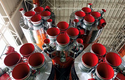
În spațiul rusesc Soyuz-2, pe lângă cele 20 de camere fixe ale sistemului de propulsie, există 12 camere de control rotative (fiecare în planul propriu) cu o dimensiune mai mică. Corpurile de direcție au un sistem comun de combustibil cu motoarele principale.
Dintre cele 11 motoare de susținere (toate etapele) ale vehiculului de lansare Saturn-5, nouă (cu excepția etapelor 1 și 2 centrale) se rotesc, fiecare în două planuri. Atunci când se utilizează motoarele principale ca comandă, intervalul de lucru al rotirii camerei nu este mai mare de ± 5 °: datorită forței mari a camerei principale și amplasării acesteia în compartimentul pupa, adică la o distanță considerabilă de centrul de masă al rachetei, chiar și o mică deformare a camerei creează un moment de control semnificativ.
Pe lângă camerele PTZ, uneori sunt folosite motoare care servesc numai pentru controlul și stabilizarea aeronavei. Două camere cu duze direcționate opus sunt fixate rigid pe corpul aparatului astfel încât forța acestor camere să creeze un moment de forță în jurul uneia dintre axele principale ale aparatului. În consecință, pentru a controla celelalte două axe sunt de asemenea setate perechi de motoare de control. Aceste motoare (de regulă, un component) sunt pornite și oprite prin comanda sistemului de comandă al aparatului, transformându-l în direcția dorită. Astfel de sisteme de control sunt utilizate în mod obișnuit pentru orientarea aeronavelor în spațiul cosmic.
- Lumea celebră LRE


Eseu pe tema:
Propulsor de rachetă cu motor lichid
Plan:
- introducere
- 1 Istorie
- 2 Domeniul de utilizare, avantaje și dezavantaje
- 3
Dispozitivul și principiul funcționării unui motor cu rachetă cu două componente
- 3.1 Sistem de combustibil
- 3.2 Sistemul de răcire
- 3.3 Lansarea LRE
- 3.4 LRE sistem automat de control
- 3.5 Componente de combustibil
- 4 Motoare cu rachete monomponent
- 5 Motoare cu rachetă tri-componente
- 6 Controlul rachetelor notițe
introducere
Motorul cu rachetă cu propulsor lichid (LRE) - un motor cu rachete chimice care utilizează lichide, inclusiv gaze lichefiate, ca combustibil pentru rachete. În ceea ce privește numărul de componente utilizate, motoarele cu rachete cu unul, doi și trei componente diferă.
1. Istorie
Posibilitatea de a folosi lichide, inclusiv hidrogen lichid și oxigen, drept combustibil pentru rachete, a fost subliniată de K.E. Tsiolkovsky în articolul "Studiul spațiilor lumii cu instrumente de jet", publicat în 1903. Primul experimental experimental LRE a fost construit de către inventatorul american R. Goddard în 1926. Evoluții similare în anii 1931-1933. au fost conduse în URSS de un grup de entuziaști sub conducerea lui F. A. Zander. Aceste lucrări au fost continuate în RNII organizat în 1933, dar în 1938 subiectul LRE a fost închis acolo, iar designerii de frunte S. P. Korolev și V. P. Glushko au fost reprimați ca "dăunători".
Cel mai mare succes în dezvoltarea LRE în prima jumătate a secolului XX. Designerii germani Walter Thiel, Helmut Walter, Werner von Braun și alții au făcut-o. În timpul celui de-al doilea război mondial, au creat o serie întreagă de motoare pentru rachete militare: V-2 balistice, Vasserfal, Schmetterling și R3 Raintochter. În 1944, în cel de-al Treilea Reich, a fost creată o nouă industrie - producția de rachete, sub îndrumarea generală a lui W. Dornberger, în timp ce în alte țări dezvoltarea LRE a fost într-o etapă experimentală.
După război, dezvoltarea designerilor germani a împins cercetarea în domeniul rachetei în URSS și în Statele Unite, unde au emigrat mulți cercetători și ingineri germani, inclusiv V. von Braun. Începutul cursei înarmărilor și rivalitatea dintre URSS și SUA pentru conducerea în explorarea spațială au fost stimulenți puternici pentru dezvoltarea LRE.
În 1957, în URSS, sub conducerea lui S. P. Korolev, a fost creat RB-7 ICBM echipat cu motorul de rachetă RD-107 și RD-108, la acel moment cel mai puternic și perfect din lume, dezvoltat sub conducerea lui V. P. Glushko. Această rachetă a fost folosită ca purtător al primului satelit artificial din lume, al primelor nave spațiale și al sondei interplanetare.
În 1969, a fost lansată prima nava spațiale Apollo în Statele Unite, lansată pe traiectoria de zbor a Lunii de către vehiculul de lansare Saturn-5, prima etapă a căruia a fost echipat cu motoarele F-1. F-1 este în prezent cel mai puternic dintre LRE cu o singură cameră, producând motorul RD-170 cu patru camere dezvoltat de biroul de proiectare Energomash din Uniunea Sovietică în 1976.
În prezent, programele spațiale ale tuturor țărilor se bazează pe utilizarea LRE.
2. Sferă de utilizare, avantaje și dezavantaje
Lansarea vehiculelor și a sistemelor de propulsie ale diferitelor nave spațiale reprezintă principalele domenii de aplicare pentru LRE.
Pentru avantajele LRE include următoarele:
- Cel mai mare impuls specific din clasa motoarelor cu rachete chimice (peste 4 500 m / s pentru perechea de oxigen-hidrogen, pentru kerosen-oxigen - 3 500 m / s).
- Manipularea pe clapeta de accelerație: prin reglarea consumului de carburant, puteți schimba cantitatea de tracțiune într-un interval mare și opriți complet motorul și reporniți-l. Acest lucru este necesar atunci când manevrați aparatul în spațiul cosmic.
- Atunci când se creează rachete mari, de exemplu, purtători care aduc încărcături pe mai multe tonuri în orbita Pământului, utilizarea motoarelor cu rachetă cu propulsor lichid face posibilă obținerea unui avantaj în greutate față de motoarele propulsate solide (motoarele cu rachetă cu propulsor solid). În primul rând, datorită impulsului specific mai mare și, în al doilea rând, datorită faptului că combustibilul lichid al rachetei este conținut în recipiente separate, din care este introdus în camera de combustie prin intermediul pompelor. Din această cauză, presiunea în rezervoare este semnificativ (de zece ori mai mică) decât în camera de ardere, în timp ce tancurile sunt ele însele cu pereți subțiri și relativ ușoare. Într-un container solid de carburant solid, rezervorul de combustibil este simultan o cameră de ardere și trebuie să reziste la o presiune ridicată (zeci de atmosfere), ceea ce implică o creștere a greutății sale. Cu cât este mai mare volumul de combustibil pe rachetă, cu atât mai mare este dimensiunea rezervoarelor pentru depozitarea sa și cu atât mai mare este avantajul de greutate al LRE comparativ cu motorul cu rachetă cu propulsor solid și invers: în cazul rachetelor mici, prezența unui ansamblu turbopump anulează acest avantaj.
Dezavantaje LRE:
- Motoarele cu rachete lichide și o rachetă bazată pe acestea sunt mult mai complicate și mai scumpe decât combustibilii solizi echivalenți (în ciuda faptului că 1 kg de combustibil lichid este de câteva ori mai ieftin decât combustibilul solid). Este necesar să se transporte o rachetă lichidă cu măsuri de precauție mai mari, iar tehnologia de pregătire pentru lansare este mai complicată, consumatoare de timp și necesită mai mult timp (mai ales atunci când se utilizează gaze lichefiate ca componente de combustibil), prin urmare, pentru rachetele militare, acum este preferabil motoarele propulsate solide. fiabilitate ridicată, mobilitate și pregătire.
- Componentele combustibilului lichid în lipsa greutății se mișcă necontrolat în spațiul rezervoarelor. Pentru ei depunere ar trebui luate măsuri speciale, de exemplu, pentru a include motoare auxiliare care funcționează pe combustibil solid sau gaz.
- În prezent, pentru motoarele cu rachete chimice (inclusiv pentru motoarele cu rachetă cu combustibil lichid) a fost atinsă limita posibilităților de alimentare cu combustibil și, prin urmare, teoretic nu este prevăzută o creștere semnificativă a impulsului lor specific, ceea ce limitează capacitățile tehnologiei rachetelor bazate pe utilizarea motoarelor chimice deja dezvoltate în două direcții. :
- Zboruri spațiale în spațiul apropiat de Pământ (atât cu echipaj uman cât și fără pilot).
- Explorarea spațiului din sistemul solar folosind nave spațiale automate (Voyager, Galileo).
3. Dispozitivul și principiul funcționării unui motor cu rachetă cu două componente
Fig. 1 schemă motor cu rachetă bicomponentă
1 - linia de combustibil
2 - linia de oxidant
3 - pompă de combustibil
4 - pompă de oxidant
5 - turbină
6 - generator de gaz
7 - supapa generatorului de gaz (combustibil)
8 - supapa generatorului de gaz (oxidant)
9 - supapa de alimentare principală
10 - supapa principală a oxidantului
11 - evacuarea turbinei
12 - cap de amestecare
13 - Camera de combustie
14 - duza
Există o varietate destul de mare de scheme pentru organizarea LRE, cu unitatea principiului principal al funcționării lor. Luați în considerare dispozitivul și principiul LRE pe exemplul unui motor bicomponent cu combustibil de pompare, cel mai des întâlnit, a cărui schemă a devenit clasică. Alte tipuri de LRE (cu excepția celui cu trei componente) sunt variante simplificate ale celei luate în considerare și, în descrierea acestora, va fi suficient să se indice simplificările.
În fig. 1 arată schematic dispozitivul LRE.
Componentele combustibilului - combustibil (1) și oxidant (2) provin de la rezervoare la pompe centrifuge (3, 4) antrenate de o turbină cu gaz (5). Sub presiune ridicată, componentele combustibilului ajung la duza cap (12) - o unitate în care sunt plasate duze, prin care componentele sunt injectate în camera de combustie (13), amestecate și arse, formând un fluid de lucru gazos încălzit la o temperatură ridicată, care, extinzându-se în duza, efectuează lucrarea și transformă energia internă a gazului în cinetică energia mișcării sale direcționale. Prin duza (14), gazul expiră la viteză mare, dând forța jetului motorului.
3.1. Sistem de combustibil
Ansamblul Turbopump Assembly (TNA) LRE V-2 în secțiune. Turbină rotor în mijloc. Rotiți pompa pe părțile laterale ale acesteia
Sistemul de injecție a combustibilului din LRE include toate elementele care servesc la alimentarea cu combustibil a camerei de ardere - rezervoare de combustibil, conducte, unitatea de pompare turbo (THA) - unitatea constând din pompe și o turbină montată pe un singur arbore, un cap de duze și supape care reglează fluxul de combustibil.
Pompa de alimentare combustibil vă permite să creați o presiune înaltă în camera motorului, de la zeci de atmosfere la 250 de litri (LRE 11D520 PH Zenit). Presiunea înaltă asigură un grad mai mare de extindere a fluidului de lucru, care este o condiție prealabilă pentru obținerea unei valori ridicate a impulsului specific. În plus, cu presiune ridicată în camera de combustie, se obține cea mai bună valoare. raport tracțiune-greutate motor - raportul dintre mărimea tracțiunii și greutatea motorului. Cu cât valoarea acestui indicator este mai mare, cu atât dimensiunea și greutatea motorului sunt mai mici (cu aceeași valoare a presiunii) și cu cât este mai mare gradul de perfecționare. Avantajele sistemului de pompare sunt deosebit de pronunțate într-un motor cu rachete mare, de exemplu în sistemele de propulsie cu rachete.
În figura 1, gazele de eșapament de la turbina turbinei turbine curg prin capul duzei în camera de combustie împreună cu componentele combustibilului (11). Un astfel de motor este numit motor cu buclă închisă (altfel - cu un ciclu închis), în care întregul consum de combustibil, inclusiv cel utilizat în unitatea TNA, trece prin camera de combustie LRE. Presiunea la ieșirea turbinei într-un astfel de motor ar trebui, evident, să fie mai mare decât în camera de combustie LRE și la intrarea în generatorul de gaze (6) care alimentează turbina, chiar mai mare. Pentru a îndeplini aceste cerințe, aceleași componente ale combustibilului (sub presiune înaltă) sunt utilizate pentru acționarea turbinei (unde LRE funcționează în sine (cu un raport diferit de componente, de regulă, cu un exces de combustibil pentru a reduce sarcina termică pe turbină).
O alternativă la o buclă închisă este buclă deschisăîn care turbina de evacuare este produsă direct în mediu prin conducta de evacuare. Punerea în aplicare a ciclului deschis este mai simplă din punct de vedere tehnic, deoarece operațiunea turbinei nu este legată de funcționarea camerei LRE, iar în acest caz, THA poate avea, în general, un sistem independent de combustibil, ceea ce simplifică procedura de pornire a întregului sistem de propulsie. Dar sistemele cu ciclu închis au valori impulsive specifice ușor mai bune și acest lucru îi determină pe designeri să depășească dificultățile tehnice de punere în aplicare a acestora, în special pentru motoarele de lansare de mari dimensiuni, la care se fac cerințe deosebit de ridicate asupra acestui indicator.
În diagrama din fig. 1 THA injectează ambele componente, ceea ce este acceptabil în cazurile în care componentele au densități proporționale. Pentru cele mai multe lichide utilizate ca componente de propulsor, densitatea variază în intervalul 1 ± 0,5 g / cm³, ceea ce permite utilizarea unei singure unități turbo pentru ambele pompe. Excepția este hidrogenul lichid, care la o temperatură de 20 ° K are o densitate de 0,071 g / cm3. Pentru un astfel de lichid ușor, este necesară o pompă cu caracteristici complet diferite, inclusiv cu o viteză de rotație mult mai mare. Prin urmare, în cazul utilizării hidrogenului drept combustibil, pentru fiecare componentă este prevăzut un THA independent.
Cu un motor mic (și, prin urmare, un consum redus de combustibil), ansamblul turbopump devine un element prea "greu", agravând caracteristicile de greutate ale sistemului de propulsie. Un sistem alternativ de alimentare cu combustibil este excludere, în care fluxul de combustibil în camera de combustie este asigurat de presiunea impulsului din rezervoarele de combustibil, create de gaz comprimat, cel mai adesea azot, care este necombustibil, netoxic, nu este un oxidant și este relativ ieftin în producție. Pentru presurizarea rezervoarelor cu hidrogen lichid, se utilizează heliu, deoarece alte gaze se condensează la temperatura hidrogenului lichid și se transformă în lichid.
Când se ia în considerare funcționarea motorului cu sistemul de injecție a combustibilului din schema din Fig. 1 THA este exclusă, iar componentele combustibilului provin din rezervoare direct la supapele principale ale LRE (9) și (10). Presiunea în rezervoarele de combustibil în timpul fluxului de presiune trebuie să fie mai mare decât în camera de combustie, tancurile - mai puternice (și mai grele) decât în cazul unui sistem de alimentare cu combustibil. În practică, presiunea din camera de combustie a motorului cu alimentare cu combustibil sub presiune este limitată la 10-15 sec. În mod tipic, aceste motoare au o presiune relativ mică (în termen de 10 tone). Avantajele sistemului de presiune sunt simplitatea designului și viteza răspunsului motorului la comanda de pornire, în special în cazul utilizării componentelor de combustibil auto-aprindere. Astfel de motoare servesc pentru a efectua manevre de nave spațiale în spațiul cosmic. Sistemul de deplasare a fost utilizat în toate cele trei sisteme de propulsie ale serviciului navei lunare Apollo (împingere 9,760 kgf), unelte de aterizare (4 760 kgf) și decolare (1 950 kgf).
Capul duzei - nodul în care sunt montate jeturiconcepute pentru a injecta componentele combustibilului în camera de ardere. Principala cerință pentru duze este aceea de a amesteca componentele cât mai rapid și mai bine pe măsură ce intră în cameră, deoarece viteza lor de aprindere și ardere depind de ea.
Prin capul de injecție al motorului F-1 (în limba engleză), de exemplu, 1,8 tone de oxigen lichid și 0,9 tone de kerosen intră în camera de combustie în fiecare secundă. Timpul petrecut de fiecare parte a acestui combustibil și de produsele sale de combustie în cameră este în milisecunde. În acest timp, combustibilul ar trebui să ardă cât mai mult posibil, deoarece combustibilul nearsă este pierderea de împingere și impulsul specific. Soluția la această problemă se realizează printr-o serie de măsuri:
- Creșterea maximă a numărului de duze din cap, cu o minimizare proporțională a debitului printr-o duză. (În capul duzei motorului F1 sunt instalate 2600 duze pentru oxigen și 3700 duze pentru kerosen.
- Geometria specială a amplasării injectoarelor în cap și ordinea alternării injectorilor de combustibil și oxidant.
- Forma specială a canalului duzei, datorită căreia rotația se deplasează prin canalul de fluid și rotația este împrăștiată când intră în cameră prin forța centrifugală.
3.2. Sistemul de răcire
Datorită vitezei proceselor care se produc în camera de combustie LRE, doar o parte nesemnificativă (fracțiuni procentuale) din toată căldura generată în cameră este transferată la proiectarea motorului, datorită temperaturii înalte de ardere (uneori peste 3000 ° K) și a unei cantități semnificative de căldură, chiar o mică parte este suficientă pentru distrugerea termică a motorului, astfel încât problema răcirii motorului cu rachete este foarte importantă.
Pentru LRE cu alimentare cu combustibil de pompare, două metode de răcire a pereților camerei LRE sunt utilizate în principal: răcire regenerativă și perete stratcare sunt adesea împărtășite. Pentru motoarele mici cu sistem de injecție de combustibil utilizat frecvent ablativ metoda de răcire.
Designul tubular al duzelor și camerelor LRE Titan I.
Răcire prin răcire este că în peretele camerei de ardere și în partea superioară și cea mai încălzită a duzelor, într-un fel sau altul, este creată o cavitate (uneori numită "jachetă de răcire") prin care trece una dintre componentele combustibilului (de obicei combustibil) înainte de a intra în capul de amestecare, răcirea peretelui camerei. Căldura absorbită de componenta de răcire revine în cameră împreună cu agentul de răcire în sine, ceea ce justifică numele sistemului - "regenerativ".
Dezvoltarea diferitelor tehnici tehnologice pentru crearea unei jachete de răcire. Camera camerei rachetei LRE V-2, de exemplu, a constat din două cochilii de oțel, interne și externe, repetând forma una de cealaltă. O componentă de răcire (etanol) a trecut prin decalajul dintre aceste cochilii. Datorită deviațiilor tehnologice ale grosimii gap-ului, a apărut o neuniformitate a fluxului de fluid, ceea ce a dus la crearea unor zone de supraîncălzire locale ale carcasei interioare, care adesea "ardea" în aceste zone, cu consecințe catastrofale.
În motoarele moderne, interiorul peretelui camerei este realizat din aliaje de bronz cu conductivitate ridicată. Se creează canale înguste, cu pereți subțiri, utilizând metoda de frezare (15D520 PH 11K77 Zenit, PH 11K25 Energy) sau gravarea acidă (SSME Space Shuttle). Din exterior, această structură este înfășurată în jurul mantalei din oțel sau titan, care percepe sarcina de putere a presiunii interne a camerei. O componentă de răcire circulă prin canale. Uneori, jacheta de răcire este asamblată din tuburi subțiri conducătoare de căldură, care sunt etanșate pentru etanșarea cu un aliaj de bronz, dar astfel de camere sunt proiectate pentru presiuni mai mici.
Strat de perete (stratul de frontieră, americanii folosesc și termenul "perdea" - perdea) - acesta este un strat de gaz în camera de combustie situată în imediata vecinătate a peretelui camerei și constând în principal din vapori de combustibil. Pentru organizarea unui astfel de strat, numai duzele de combustibil sunt instalate de-a lungul periferiei capului de amestecare. Datorită unui exces de combustibil și a lipsei unui agent de oxidare, reacția de combustie chimică din stratul din peretele apropiat este mult mai puțin intensă decât în zona centrală a camerei. Ca urmare, temperatura stratului din peretele apropiat este semnificativ mai mică decât temperatura din zona centrală a camerei și izolează peretele camerei de contactul direct cu cele mai fierbinți produse de ardere. Uneori, pe lângă acestea, duzele sunt instalate pe pereții laterali ai camerei, conducând o parte a combustibilului în cameră direct din mantaua de răcire, de asemenea cu scopul de a crea un strat de perete aproape.
ablativ metoda de răcire constă într-o acoperire specială de protecție împotriva căldurii a camerei și pereților duzei. Această acoperire este, de obicei, mai multe straturi. Straturile interioare constau din materiale termoizolante la care se aplică ablativ un strat constând dintr-o substanță capabilă să treacă de la o fază solidă direct la o gază atunci când este încălzită și, în același timp, să absoarbă o cantitate mare de căldură în această transformare de fază. Stratul de ablație se evaporă treptat, asigurând protecție termică a camerei. Această metodă este practicată în motoarele cu rachete mici, cu o încărcătură de până la 10 tone. În astfel de motoare, consumul de combustibil este de numai câteva kilograme pe secundă, iar acest lucru nu este suficient pentru a asigura o răcire regenerativă intensivă. Răcirea ablativă a fost utilizată în sistemele de propulsie ale navei lunare Apollo.
3.3. Lansați motorul cu rachete
Lansarea motorului cu rachete este o operațiune responsabilă, plină de consecințe grave în situații de urgență în cursul implementării sale.
Dacă sunt componentele combustibilului pyrophoric, adică intrarea într-o reacție chimică de ardere în timpul contactului fizic între ele (de exemplu, acidul heptil / acid azotic), inițierea procesului de ardere nu cauzează probleme. Dar în cazul în care componentele nu sunt astfel, este nevoie de un dispozitiv de aprindere extern, a cărui acțiune trebuie să fie precis coordonată cu alimentarea componentelor combustibilului în camera de ardere. Combinația combustibilului nearsă este un explozibil de mare putere distructivă, iar acumularea sa în camera amenință cu un accident sever.
După aprinderea combustibilului, menținerea unui proces continuu de combustie are loc prin el însuși: combustibilul care reintră în camera de ardere se aprinde datorită temperaturii ridicate create de arderea porțiunilor introduse anterior.
Pentru pornirea inițială a combustibilului din camera de combustie la pornirea LRE, se utilizează diferite metode:
- Folosirea componentelor cu auto-aprindere (de obicei bazate pe combustibil de pornire care conține fosfor, auto-aprindere atunci când interacționează cu oxigenul), care, la începutul procesului de pornire a motorului, sunt introduse în cameră prin duze suplimentare adiționale din sistemul auxiliar de combustibil, iar după pornirea combustiei, componentele principale sunt furnizate. Prezența unui sistem suplimentar de combustibil complică proiectarea motorului, dar permite reluarea acestuia în mod repetat.
- Un incendiu electric amplasat în camera de combustie lângă capul de amestecare, care, atunci când este pornit, creează un arc electric sau o serie de descărcări de scânteie de înaltă tensiune. Acest declanșator este de unică folosință. După aprinderea combustibilului, arde.
- Declanșator pirotehnic. Lângă capul de amestecare din cameră se află o mică piesă pirotehnică de acțiune incendiară, care este aprinsă de o siguranță electrică.
Înregistrarea automată a motorului coordonează în timp acțiunea declanșatorului și alimentarea cu combustibil.
Lansarea LRE-urilor mari cu un sistem de combustibil de pompare constă în mai multe etape: THA pornește prima dată și preia viteza (acest proces poate consta și în mai multe faze), apoi valvele principale ale LRE se aprind, de obicei în două sau mai multe trepte, pași până la normal.
Pentru motoarele relativ mici, începând cu eliberarea LRE-urilor se practică imediat la o tracțiune de 100%, numită "tun".
3.4. LRE sistem automat de control
Modern LRE este furnizat cu o automatizare destul de complexă, care ar trebui să îndeplinească următoarele sarcini:
- Începerea sigură a motorului și ieșirea acestuia în modul principal.
- Mențineți o funcționare stabilă.
- Modificarea tracțiunii în conformitate cu programul de zbor sau la comanda sistemelor de control extern.
- Oprirea motorului când racheta atinge orbita specificată (traiectoria).
- Reglarea raportului consumului de componente.
Sistemul de control automat al sistemului de propulsie include senzori de presiune și debit în diferite puncte ale sistemului de alimentare cu combustibil, iar corpurile sale executive sunt valvele principale ale supapei de comandă a rachetelor lichidelor și a turbinelor (fig.1 - pozițiile 7, 8, 9 și 10).
3.5. Componente de combustibil
Alegerea componentelor combustibilului este una dintre cele mai importante decizii în proiectarea unui LRE, care determină multe detalii ale designului motorului și ale soluțiilor tehnice ulterioare. Prin urmare, alegerea combustibilului pentru LRE se realizează cu o considerație cuprinzătoare a scopului motorului și rachetei pe care este instalat, condițiile de funcționare, tehnologia de producție, depozitare, transport la locul de lansare etc.
Unul dintre cei mai importanți indicatori care caracterizează combinația de componente este impuls specific, care este deosebit de important în proiectarea vehiculelor de lansare a navelor spațiale, deoarece raportul dintre masa combustibilului și sarcina utilă și, în consecință, mărimea și masa întregii rachete (a se vedea formula Tsiolkovsky), care, cu o insuficientă specificitate Momentul poate fi ireal. Tabelul 1 prezintă principalele caracteristici ale unor combinații de componente ale combustibilului lichid.
Tabelul 1.| Agent de oxidare | combustibil | Densitatea medie combustibil, g / cm3 |
Temperatura camerei ardere, ° K |
Specific specific impuls cu |
|---|---|---|---|---|
| oxigen | hidrogen | 0,3155 | 3250 | 428 |
| petrol lampant | 1,036 | 3755 | 335 | |
| 0,9915 | 3670 | 344 | ||
| hidrazină | 1,0715 | 3446 | 346 | |
| amoniac | 0,8393 | 3070 | 323 | |
| diazota tetraoxid | petrol lampant | 1,269 | 3516 | 309 |
| Dimetilhidrazina asimetrică | 1,185 | 3469 | 318 | |
| hidrazină | 1,228 | 3287 | 322 | |
| fluor | hidrogen | 0,621 | 4707 | 449 |
| hidrazină | 1,314 | 4775 | 402 | |
| pentaborane | 1,199 | 4807 | 361 |
Pe lângă impulsul specific în alegerea componentelor combustibililor, alți indicatori ai proprietăților combustibililor pot juca un rol decisiv, inclusiv:
- densitatecare afectează dimensiunea componentelor rezervorului. După cum urmează din tabel. 1, hidrogenul este combustibil, cu cel mai mare impuls specific (cu orice agent de oxidare), dar are o densitate extrem de scăzută. Prin urmare, primele etape ale vehiculelor de lansare utilizează de obicei alte tipuri de combustibil (mai puțin eficiente, dar mai dens), de exemplu kerosen, ceea ce face posibilă reducerea dimensiunilor primei etape la cele acceptabile. Exemple de astfel de "tactici" sunt racheta Saturn-5, prima etapă din care utilizează componente oxigen / kerosen și etapele a doua și a treia sunt oxigenul / hidrogenul și sistemul de navetă spațială, în care sunt folosite ca primă etapă boosters cu combustibil solid.
- Punct de fierbere, care pot impune restricții serioase asupra condițiilor de funcționare a rachetelor. Conform acestui indicator, componentele combustibililor lichizi sunt împărțiți în criogenie - gazele lichefiate răcite la temperaturi extrem de scăzute; cazanele mari - lichide care au un punct de fierbere mai mare de 0 ° C.
- criogenie Componentele nu pot fi stocate pe termen lung și transportate pe distanțe lungi, astfel încât acestea trebuie să fie fabricate (cel puțin lichefiate) în industriile cu consum mare de energie situate în imediata vecinătate a locului de lansare, ceea ce face ca lansatorul să fie complet imobil. În plus, componentele criogenice au alte proprietăți fizice care impun cerințe suplimentare privind utilizarea lor. De exemplu, prezența unor cantități chiar nesemnificative de apă sau vapori de apă în tancurile cu gaze lichefiate conduce la formarea de cristale de gheață foarte solide care, atunci când sunt injectate în sistemul de combustibil al unei rachete, acționează pe componentele sale ca material abraziv și poate provoca un accident sever. În timpul orelor de pregătire a rachetelor pentru lansare, o mare cantitate de îngheț se transformă în gheață, iar căderea pieselor sale de la o înălțime mare îngheață pe ea și reprezintă un pericol pentru personalul implicat în pregătire, precum și pentru racheta însăși și pentru echipamentul de lansare. După realimentare, gazele lichefiate ale rachetei încep să se evapore și, până la momentul lansării, trebuie să fie alimentate continuu printr-un sistem special de alimentare. Gazul în exces format în timpul evaporării componentelor trebuie să fie îndepărtat astfel încât oxidantul să nu se amestece cu combustibilul, formând un amestec exploziv.
- Cazane înalte componentele sunt mult mai convenabile pentru transportul, depozitarea și manipularea acestora, astfel încât în anii 50 ai secolului al XX-lea au forțat componente criogenice din domeniul producerii de rachete militare. În viitor, această zonă se implică din ce în ce mai mult în combustibil solid. Dar atunci când se creează transportoare spațiale, combustibilii criogenici își mențin poziția în detrimentul eficienței energetice ridicate și pentru a efectua manevre în spațiul cosmic, atunci când combustibilul trebuie să rămână în tancuri timp de luni sau chiar ani, componentele cu punct de fierbere ridicat sunt cele mai acceptabile. O ilustrare a unei astfel de "diviziuni a forței de muncă" poate fi LRE implicate în proiectul Apollo: toate cele trei etape ale vehiculului de lansare Saturn-5 utilizează componente criogenice, iar motoarele navei lunare destinate să corecteze traiectoria și pentru manevrele pe orbita lunii apropiate sunt dimetilhidrazina și tetraoxidul asimetric diazot.
- Agresivitatea chimică. Toți oxidatorii au această calitate. Prin urmare, chiar și cantități nesemnificative de substanțe organice (de exemplu, petele grase lăsate de degetele umane) în rezervoarele destinate oxidantului pot provoca un incendiu care poate provoca arderea materialului rezervorului (aluminiu, magneziu, titan și fier ard foarte puternic în oxidantul de rachetă ). Datorită agresivității, oxidanții nu sunt folosiți în mod obișnuit ca agenți de răcire în sistemele de răcire LRE și în generatoarele de gaz TNA pentru a reduce încărcătura termică a turbinei, fluidul de lucru este suprasaturat cu combustibil și nu cu oxidant. La temperaturi scăzute, oxigenul lichid este probabil cel mai sigur agent de oxidare, deoarece agenții alternativi de oxidare, cum ar fi diazo-tetroxidul sau acidul azotic concentrat, reacționează cu metalele și, deși sunt agenți oxidanți cu temperatură în fierbere care pot fi păstrați pentru o lungă perioadă de timp la temperatura normală Tancurile în care sunt amplasate sunt limitate.
- toxicitate componentele combustibilului și produsele lor de ardere reprezintă un limitator serios al utilizării acestora. De exemplu, fluor, după cum se arată în Tabelul 1. Ca agent de oxidare, este mai eficient decât oxigenul, dar când este asociat cu hidrogen, formează acid fluorhidric - o substanță extrem de toxică și agresivă și eliberarea a câteva sute, mai ales mii de tone de produs de combustie atmosfera de lansare a unei mari rachete este, în sine, un dezastru major, chiar și cu o lansare reușită. Și în caz de accident și de scurgere a unei astfel de cantități de substanță, daunele nu sunt luate în calcul. Prin urmare, fluorul nu este utilizat ca component de combustibil. Tetroxidul de azot, acidul azotic și dimetilhidrazina asimetrică sunt, de asemenea, toxice. În prezent, oxidantul preferat (din punct de vedere al mediului) este oxigenul, iar combustibilul este hidrogen, urmat de kerosen.
4. Motoare cu rachetă cu un singur component
În motoarele cu un singur component, lichidul este utilizat drept combustibil, care, atunci când interacționează cu catalizatorul, se descompune pentru a forma gaze fierbinți. Exemple de astfel de lichide sunt hidrazina, care se descompune în amoniac și hidrogen sau peroxid de hidrogen concentrat, care, atunci când se descompune, formează vapori de apă supraîncălzită și oxigen. Deși LRE cu un singur component dezvoltă un mic impuls specific (în intervalul de la 150 la 255 s) și sunt mult mai puțin eficiente față de cele două componente, avantajul lor este simplitatea designului motorului.
Combustibilul este depozitat într-un singur recipient și este alimentat printr-o singură linie de combustibil. În LRE-urile cu un singur component, se utilizează numai sistemul de injecție a combustibilului. Problema amestecării componentelor în cameră nu există. Sistemul de răcire este de obicei absent, deoarece temperatura reacției chimice nu depășește 600 ° C. Când se încălzește, camera motorului disipează căldura prin radiație și temperatura acesteia este menținută la un nivel care nu depășește 300 ° C. Motorul cu rachete cu o singură componentă nu are nevoie de un sistem de control complex.
Sub acțiunea presiunii de deplasare, combustibilul intră în camera de ardere prin supapa, în care un catalizator, de exemplu oxidul de fier, cauzează descompunerea acestuia.
Motoarele cu rachete monomponent sunt folosite în mod obișnuit ca propulsoare (uneori împingerea lor este doar câteva newtoni) în sistemele de orientare și stabilizare a navelor spațiale și a rachetelor tactice, pentru care simplitatea, fiabilitatea și masa redusă a structurii sunt criteriile definitorii.
Un exemplu excelent este utilizarea unui propulsor de hidrazină la bordul primului satelit de comunicații american TDRS-1; Acest motor a funcționat timp de câteva săptămâni pentru a aduce satelitul în orbită geostaționară, după ce un accident a avut loc pe accelerator și satelitul se afla într-o orbită mult mai joasă.
Un exemplu de utilizare a unui motor cu rachetă mono-componentă poate servi, de asemenea, ca motoare cu presiune redusă în sistemul de stabilizare a vehiculului de coborâre al navei spațiale Soyuz.
Motoarele cu rachetă monomponentă nu includ dispozitive reactive care funcționează pe gaz rece comprimat (de exemplu aer sau azot). Astfel de motoare se numesc jeturi de gaz și constau dintr-o supapă și o duză. Motoarele cu jet de gaze sunt folosite atunci când efectele termice și chimice ale jetului de evacuare sunt inacceptabile și în cazul în care cerința de bază este simplitatea designului. Aceste cerințe trebuie îndeplinite, de exemplu, de către dispozitive individuale de mișcare și manevrare a astronauților (UPMK) situate în rucsacul din spatele lor și destinate mișcării atunci când lucrează în afara navei spațiale. UPMK funcționează din două cilindri cu azot comprimat, care este alimentat prin supape solenoidale din sistemul de propulsie, format din 16 motoare.
5. Motoare cu rachetă tri-componente
De la începutul anilor 1970, conceptul de motoare cu trei componente care ar combina un impuls specific ridicat atunci când a fost utilizat ca hidrogen combustibil și o densitate medie mai mare a combustibilului (și, prin urmare, un volum și o greutate mai mică a rezervoarelor de combustibil) a fost studiat în URSS și în SUA caracteristică a combustibilului cu hidrocarburi. La pornirea unui astfel de motor ar funcționa oxigenul și kerosenul, iar la altitudini mari a trecut la utilizarea oxigenului și a hidrogenului lichid. O astfel de abordare ar putea permite crearea unui transportator spațial într-o singură etapă. Exemplul rusesc al unui motor cu trei componente este modelul RD-701 LRE, dezvoltat pentru sistemul de transport spațial MAKS reutilizabil.
De asemenea, este posibil să se utilizeze simultan doi combustibili - de exemplu, hidrogen-beriliu-oxigen și hidrogen-litiu-fluor (ars de beriliu și litiu, iar hidrogenul este cel mai utilizat ca fluid de lucru) .
6. Controlul rachetelor
În motoarele cu rachete de lichid, adesea în plus față de funcția principală de a crea forța de tracțiune, ele servesc și ca autorități de control al zborului. Deja prima comandă de rachete balistice V-2 controlate a fost controlată cu ajutorul a 4 cârme dinamice din punct de vedere al gazului din punct de vedere al gazelor plasate în jetul de jet al motorului la periferia duzei. Deviind, aceste cârme au respins o parte a fluxului de jet, care a schimbat direcția vectorului de împingere al motorului și a creat momentul forței relativ la centrul de masă al rachetei, care a fost acțiunea de control. Această metodă reduce în mod semnificativ forța motoarelor, pe lângă cădiile de grafit dintr-un flux de jeturi sunt supuse eroziunii severe și au o resursă de timp foarte mică.
În sistemele moderne de control al rachetelor sunt utilizate camere PTZ LRE, care sunt atașate elementelor de sprijin ale corpului rachetei cu ajutorul balamalelor, permițându-vă să rotiți camera într-una sau două planuri. Componentele combustibilului sunt furnizate camerei prin intermediul unor conducte flexibile - burdufuri. Când camera se abate de la axa paralelă cu axa rachetei, forța de tracțiune a camerei creează cuplul de comandă necesar. Camerele sunt transformate de mașini de direcție hidraulice sau pneumatice care execută comenzi produse de sistemul de control al rachetelor.
În interiorul transportatorului spațial Soyuz (vezi fotografia din titlul articolului), în afară de cele 20 de camere fixe ale sistemului de propulsie, există 12 camere de comandă pivotante (fiecare în planul propriu) care controlează camere mai mici. Corpurile de direcție au un sistem comun de combustibil cu motoarele principale.
Dintre cele 11 motoare de susținere (de toate etapele) ale vehiculului de lansare Saturn-5, nouă (cu excepția etapelor 1 și 2 centrale) se rotesc, fiecare în două planuri. Atunci când se utilizează motoarele principale ca comandă, intervalul de lucru al rotirii camerei nu este mai mare de ± 5 °: datorită forței mari a camerei principale și amplasării acesteia în compartimentul pupa, adică la o distanță considerabilă de centrul de masă al rachetei, chiar și o mică deformare a camerei creează un moment de control semnificativ.
Pe lângă camerele PTZ, uneori sunt folosite motoare care servesc numai pentru controlul și stabilizarea aeronavei. Două camere cu duze îndreptate opus sunt fixate rigid pe corpul aparatului astfel încât forța acestor camere să creeze un moment de forță în jurul uneia dintre axele principale ale aparatului. În consecință, pentru a controla celelalte două axe sunt de asemenea setate perechi de motoare de control. Aceste motoare (de regulă, un component) sunt pornite și oprite prin comanda sistemului de comandă al aparatului, transformându-l în direcția dorită. Astfel de sisteme de control sunt utilizate în mod obișnuit pentru orientarea aeronavelor în spațiul cosmic.
Acest eseu se bazează pe un articol din Wikipedia rusă. , Motorul cu rachete solare.
Reactivul este înțeles ca o mișcare în care una dintre părțile sale este separată de un corp la o anumită viteză. Forța care rezultă din acest proces acționează singură. Cu alte cuvinte, îi lipsește chiar și cel mai mic contact cu corpurile externe.
în natură
În timpul sărbătorilor de vară din sud, aproape fiecare dintre noi, înotând în mare, sa întâlnit cu meduze. Dar puțini oameni au crezut că aceste animale se mișcă în același mod ca un motor cu reacție. Principiul de funcționare în natură a unui astfel de agregat poate fi observat atunci când se deplasează anumite specii de plancton marin și larve libelule. În plus, eficiența acestor nevertebrate este adesea mai mare decât cea a mijloacelor tehnice.
Cine altcineva poate demonstra în mod clar ce are motorul cu reacție principiul funcționării? Squid, caracatiță și sepie. Multe alte moluște marine fac o mișcare similară. Luați, de exemplu, setea. Ea absoarbe apa in cavitatea de ghirlanda si o arunca puternic printr-o pâlnie, pe care o conduce înapoi sau lateral. În acest caz, moluscul este capabil să facă mișcări în direcția dorită.
Principiul de funcționare cu jet de motor poate fi observată atunci când se mișcă salsa. Acest animal de mare ia apa într-o cavitate largă. După aceea, mușchii din corpul lui contractă, împingând fluidul printr-o gaură din spate. Reacția jetului rezultat permite șuncii să meargă înainte.
Marinele rachete
Dar cea mai mare perfecțiune în navigarea cu jeturi a ajuns la aceeași calmar. Chiar și forma rachetei în sine pare a fi copiată de acest locuitor al mării. Atunci când se deplasează la viteză mică, calmarul își îndoaie periodic aripioarele romboide. Dar pentru o aruncare rapida trebuie sa-si foloseasca propriul "motor cu jet". Principiul funcționării tuturor mușchilor și corpului său merită analizat în detaliu.
Squid are o mantie speciala. Acesta este țesutul muscular care-l înconjoară pe toate părțile. În timp ce se mișcă, animalul suge un volum mare de apă în această manta, aruncând brusc un jet printr-o duză specială îngustă. Astfel de acțiuni permit calmarului să se deplaseze înapoi cu o viteză de până la șaptezeci de kilometri pe oră. animalul adună într-un pachet toate cele zece tentacule, care conferă corpului o formă raționalizată. Duza are o supapă specială. Animalul îl transformă în contracție musculară. Aceasta permite marinarului să schimbe direcția. Rolul cârma în timpul mișcărilor de squid este jucat de tentaculele sale. El îi direcționează spre stânga sau spre dreapta, în jos sau în sus, evitând cu ușurință coliziunile cu diverse obstacole.
Există un tip de squid (stenoteutis), care deține titlul de cel mai bun pilot printre moluste. Descrieți principiul funcționării unui motor cu reacție - și veți înțelege de ce, în timp ce urmăriți pește, acest animal uneori sări din apă, chiar și pe punțile de nave care navighează pe ocean. Cum se întâmplă acest lucru? Pilotul de squid, în timp ce în elementul de apă, dezvoltă forța maximă de jet pentru el. Acest lucru îi permite să zboare peste valuri la o distanță de până la 50 de metri.
Dacă considerăm un motor cu reacție, principiul de funcționare al animalului pe care îl putem menționa? Aceasta, la prima vedere, caracatiță sacră. Înotătorii nu sunt la fel de rapizi ca și calmarul, dar în caz de pericol, chiar și cei mai buni sportivi își pot invidia viteza. Biologii care au studiat migrația caracatiței au descoperit că se mișcă ca și cum un motor cu reacție are principiul de funcționare.
Un animal cu fiecare flux de apă aruncat din pâlnie face un jet de doi sau chiar doi și jumătate de spurt. În același timp, caracatița înoată într-un mod ciudat - în spate.
Alte exemple de propulsie cu jet
Există rachete în lumea plantelor. Principiul unui motor cu jet poate fi observat atunci când, chiar și cu o atingere foarte ușoară, un "castravec rabdător" revine pe pedicul la viteză mare, în același timp, respingând lichidul lipicios cu semințe. În același timp, fătul însește o distanță considerabilă (până la 12 m) în direcția opusă.
Principiul de funcționare a motorului cu reacție poate fi observat și în timp ce este în barcă. Dacă pietrele grele sunt aruncate din ea în apă într-o anumită direcție, atunci se va mișca în direcția opusă. Motorul cu jet de rachete are același principiu de funcționare. Numai acolo, în loc de pietre, se folosesc gaze. Ele creează o forță reactivă care asigură mișcarea atât în aer cât și într-un spațiu descărcat.
Călătorie fantastică
Omenirea a visat mult timp despre spațiu. Acest lucru este evidențiat de operele scriitorilor de science fiction care, pentru a atinge acest scop, au oferit o varietate de mijloace. De exemplu, eroul povestirii scriitorului francez Hercule Savinen Cyrano de Bergerac a ajuns pe lună pe un vagon de fier, peste care a fost aruncat în mod constant un magnet puternic. Celebrul Munchhausen a ajuns, de asemenea, pe aceeași planetă. O tulpină de fasole gigantică la ajutat să facă călătoria.

Propulsia cu jet a fost folosită în China încă din primul mileniu î.en. Tuburile de bambus, care au fost umplute cu praf de pușcă, au servit drept rachete originale pentru distracție. Apropo, proiectul primei mașini de pe planeta noastră, creat de Newton, a fost, de asemenea, cu un motor cu reacție.
Istoria RD
Numai în secolul al XIX-lea. visul omenirii despre spațiu a început să dobândească trăsături concrete. La urma urmei, în acest secol, primul revoluționar din lume cu un motor cu reacție a fost creat de revoluționarul rus N. I. Kibalchich. Toate lucrările au fost elaborate de către Liberatorul Poporului în închisoare, unde a ajuns după încercarea de asasinat asupra lui Alexander. Dar, din păcate, pe 03/04/1881, Kibalchich a fost executat, iar ideea lui nu a găsit implementarea practică.
La începutul secolului al XX-lea. ideea utilizării rachetelor pentru zborul spațial a fost avansată de către omul de știință rus K. E. Tsiolkovsky. Pentru prima dată, lucrarea sa, care conține o descriere a mișcării unui corp de masă variabilă sub forma unei ecuații matematice, a fost publicată în 1903. Mai târziu, omul de știință a dezvoltat chiar schema unui motor cu reacție, condus de combustibil lichid.
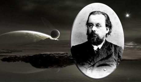
De asemenea, Tsiolkovsky a inventat o rachetă în mai multe etape și a sugerat crearea de orașe spațiale reale în orbita apropiată de pământ. Tsiolkovsky a dovedit în mod convingător că singurul mijloc de zbor în spațiu este o rachetă. Asta este, dispozitivul este echipat cu un motor cu reacție, alimentat cu combustibil și oxidant. Numai o astfel de rachetă este capabilă să depășească forța gravitației și să zboare dincolo de atmosfera Pământului.
Explorarea spațiului
Ideea lui Tsiolkovski a fost pusă în aplicare de oamenii de știință sovietici. Conduceți de Serghei Pavlovich Korolev, au lansat primul satelit Pământ artificial. La 4 octombrie 1957, acest dispozitiv a fost livrat pe orbită printr-o rachetă cu un motor cu reacție. Lucrarea RD sa bazat pe conversia energiei chimice, care este transmisă de combustibil la jetul de gaz, transformându-se în energie cinetică. În acest caz, racheta se mișcă în direcția opusă.

Motorul cu jet, a cărui principiu a fost folosit de mulți ani, își găsește aplicația nu numai în astronauti, ci și în aviație. Dar, mai presus de toate, este folosit pentru că, la urma urmei, numai RD este în măsură să se deplaseze aparatul într-un spațiu în care orice mediu este absent.
Motorul cu jet de lichid
Cel care a tras dintr-o armă de foc sau pur și simplu a urmărit acest proces din lateral, știe că există o forță care va împinge cu siguranță barilul înapoi. Și cu o sumă mai mare de taxă, întoarcerea va crește cu siguranță. Motorul cu reacție funcționează la fel. Principiul funcționării sale este similar cu modul în care cilindrul este împins înapoi sub acțiunea unui jet de gaze fierbinți.
În ceea ce privește racheta, procesul în care amestecul este aprins este gradual și continuu. Aceasta este cea mai ușoară motor cu combustibil solid. Este bine cunoscut tuturor factorilor de rachetă.
Într-un motor cu jet de lichid (LRE), un amestec constând din combustibil și un oxidant este utilizat pentru a crea un fluid de lucru sau un jet de împingere. Acesta din urmă, ca regulă, este acidul azotic sau combustibil în LRE este kerosen.
Principiul de funcționare a motorului cu reacție, care a fost în primele probe, a fost păstrat până în prezent. Doar acum se utilizează. Când această substanță este oxidată, impulsul specific crește cu 30% în comparație cu primele LRE. Merită să spunem că ideea utilizării hidrogenului a fost propusă însuși de către Tsiolkovski. Cu toate acestea, dificultățile de a lucra cu această substanță extrem de explozivă la acel moment au fost pur și simplu insurmontabile.
Care este principiul de funcționare al unui motor cu reacție? Combustibilul și oxidantul intră în camera de lucru din rezervoare separate. Următoarea este transformarea componentelor în amestec. Arde, în timp ce eliberează o cantitate mare de căldură sub presiune în zeci de atmosfere.
Componentele din camera de lucru a unui motor cu reacție se încadrează în moduri diferite. Oxidantul este introdus aici direct. Dar combustibilul merge mai departe între pereții camerei și duza. Aici se încălzește și, având deja o temperatură ridicată, este aruncat în zona de combustie prin numeroase duze. Apoi, jetul format de duză, se rupe și oferă aeronavei cu un moment de împingere. Acesta este modul în care puteți afla ce motor cu jet are principiul de funcționare (pentru scurt timp). În această descriere nu sunt menționate mai multe componente, fără care operarea LRE ar fi imposibilă. Printre acestea sunt compresoarele necesare pentru a crea presiunea necesară injecției, o supapă, turbine de alimentare, etc.
Utilizare modernă
În ciuda faptului că munca unui motor cu reacție necesită o cantitate mare de combustibil, LRE continuă să servească astăzi oamenii. Acestea sunt utilizate ca motoare principale de propulsie în vehiculele de lansare, precum și de manevră pentru diverse nave spațiale și stații orbitale. În sectorul aviației, se folosesc alte tipuri de căi de rulare, care au o performanță și un design ușor diferite.
Dezvoltarea aviației
De la începutul secolului al XX-lea, până la epuizarea celui de-al doilea război mondial, oamenii au zburat numai pe avioane cu elice. Aceste vehicule erau echipate cu motoare. ardere internă. Cu toate acestea, progresul nu sa oprit. Odată cu dezvoltarea sa, a existat necesitatea creării unor aeronave mai puternice și mai rapide. Cu toate acestea, aici, designerii de aeronave s-au confruntat cu o problemă aparent insolubilă. Faptul este că, chiar și cu o ușoară creștere, a crescut semnificativ greutatea aeronavei. Cu toate acestea, o cale de ieșire din creatorul situației a fost găsită de englezul Frank Will. El a creat fundamental noul motornumit reactiv. Această invenție a dat un impuls puternic dezvoltării aviației.

Principiul de funcționare al motorului cu reacție al aeronavei este similar cu acțiunea unui motor de incendiu. Furtunul său are un capăt conic. Trecând printr-o deschidere îngustă, apa crește semnificativ viteza. Forța de contrapresiune creată de acest lucru este atât de puternică încât pompierul nu ține prea mult furtunul în mâini. Acest comportament al apei poate explica, de asemenea, principiul de funcționare al motorului cu reacție al unei aeronave.
Taxiuri cu flux direct
Acest tip de motor cu reacție este cel mai simplu. Puteți să o prezentați sub forma unei țevi cu capete deschise, care este instalată pe un plan în mișcare. În fața secțiunii transversale se extinde. Datorită acestui design, aerul de intrare reduce viteza și crește presiunea. Cel mai larg loc al unei astfel de țevi este o cameră de ardere. Iată injecția de combustibil și arderea ulterioară. Un astfel de proces contribuie la încălzirea gazelor rezultate și la extinderea puternică a acestora. Când se întâmplă acest lucru, forța motoarelor cu reacție. Se produce toate aceleași gaze, atunci când cu o forță scos din capătul îngust al țevii. Aceasta este forța care face avionul să zboare.
Probleme de utilizare
Motoarele Ramjet au unele dezavantaje. Ei pot lucra numai pe planul care este în mișcare. Aeronava care se află într-o stare de repaus, căile de circulație directă nu poate declanșa. Pentru a se ridica în aer, o astfel de aeronavă are nevoie de orice motor de pornire.
Rezolvarea problemelor
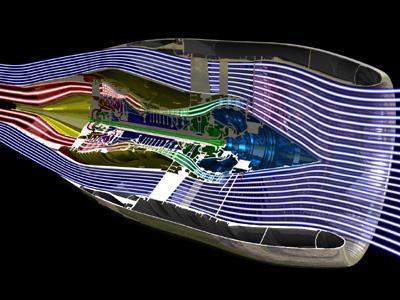
Principiul de funcționare al motorului cu reacție al unei aeronave tip turbojet, care este lipsit de dezavantajele unui RD direct-flow, permite proiectanților de aeronave să creeze cele mai avansate aeronave. Cum funcționează această invenție?
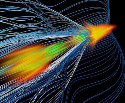
Elementul principal al motorului turbojet este turbină cu gaz. Cu ajutorul său, un compresor de aer este activat, trecând prin care aerul comprimat este direcționat într-o cameră specială. Combustia rezultată a produselor de combustibil (de obicei, kerosen) se încadrează pe paletele turbinelor, ceea ce le aduce în acțiune. Apoi, fluxul de aer-gaze intră în duză, unde accelerează la viteze mari și creează o forță extraordinară de jet.
Creșterea puterii
Tractarea reactivă poate crește semnificativ într-o perioadă scurtă de timp. Pentru aceasta, se folosește afterburning. Este injecția de combustibil suplimentar în curentul de gaze care iese din turbină. Oxigenul neutilizat din turbină contribuie la arderea kerosenului, ceea ce mărește forța motoarelor. La viteze mari, creșterea valorii sale atinge 70%, iar la viteze reduse - 25-30%.
motor rachetă lichid în camera de ardere cuprinde un gazovod circuit închis, un cap cu două plăci de capăt și montat într-un duze din două componente gaz-lichid sunt formate ca succesive mai mici cu diametrul cilindrului de intrare gazovod care acționează și un randament mai mare. În canalul central al duzele, două rânduri de deschideri tangențiale pentru alimentarea componentei lichide sunt situate în punctul de tranziție al unui diametru mai mic la unul mai mare. Camera de amestec este realizată cu o lungime de 1,4 - 1,5 diametrul de ieșire al duzei duzei. Canalul central direct în fața găurilor tangențiale este realizat sub forma unui difuzor. Invenția protejează dependențele definiției diametrelor de intrare și ieșire ale difuzorului și ale ajutajelor proeminente în orificiul de evacuare a gazului. Această realizare a camerei de ardere crește eficiența și durabilitatea procesului de lucru al motorului. 4 il.
Invenția se referă la camerele de combustie ale motoarelor cu rachetă de lichid cu circuit închis.
Cunoscutul motor de rachete cu combustibil lichid în camera de ardere J-2, compania Rokitdaydn (SUA), care lucrează la componentele combustibilului hidrogen-oxigen. Capul acestei camere conține duze bicomponente, prin canalul central al cărui oxigen lichid este furnizat, prin găurile radiale - hidrogen. Un manșon cilindric de separare este tăiat între canalele de oxigen și hidrogen într-o anumită cantitate de la duza (JA Schelke Astronatics 1962, Vor 7, N 2, p. 41, 98. O colecție de traduceri ale articolelor publicate în presa străină " motoare de rachetă"CIAM, Inventory 8942, 1963. Totuși, datorită micșorării, manșonul de separare împiedică amestecarea componentelor în interiorul duzei și, prin urmare, necesită o lungime mare a camerei de ardere pentru a asigura arderea completă necesară a combustibilului.
Jetoane duale cu jet-centrifugare similare sunt utilizate în camera de combustie a unui motor cu rachetă lichidă a circuitului închis SSME al companiei americane Rokidain pentru naveta spațială a navetei spațiale (Levin VR, Ilyin DV, Lipatov I.N., Galankin E. Moscova, American Oxigen-Hydrogenic LRE Rokidain SSME, CIAM Proceedings, Inv. 1018, 1982). In aceste duze, oxigenul lichid este de asemenea furnizat prin canalul central, iar gazul generator generat de hidrogen este alimentat prin orificiile radiale. Pentru îmbunătățirea amestecării componentelor combustibilului în interiorul duzei, manșonul de separare este tăiat la 6,1 mm cu un diametru al camerei de amestecare de 6,35 mm (l / d = 0,96).
Cu toate acestea, chiar și în astfel de duze, eficiența amestecării componentelor combustibilului este insuficientă datorită lungimii mici a contactului lor, prezența unui manșon de separare între stratul de gaz hidrogen și fluxul de oxigen din lichid. În plus, conductivitatea acustică a găurilor tangențială este mică și nu este furnizată la reglare. Conductivitatea acustică a canalului central al duzei este, de asemenea, mică datorită diametrului său mic și lungimii sale neoptimale. Prin urmare, designul camerei de combustie este complicat de partițiile antipulsare și de absorbantul acustic.
Prezenta invenție se referă la îmbunătățirea caracterului complet al arderii combustibilului și a stabilității acustice de înaltă frecvență a procesului de lucru în camera de combustie cu duze gaz-lichid bicomponente având un canal central pentru alimentarea componentei gazoase și a deschiderilor tangențiale pentru alimentarea componentei lichide.
Această sarcină este realizată prin faptul că în canalul central al duzei se află două rânduri de găuri tangențiale la punctul de trecere a unui diametru mai mic la unul mai mare, lungimea camerei de deplasare 11 este egală cu l 1 = (1,4 ... 1,5) d 1, unde d 1 - diametrul evacuării duzei. Canalul central direct în fața găurilor tangente este realizat sub forma unui difuzor (figura 2). Diametrul de intrare d 3 al difuzorului este atribuit din condiția de a asigura permeabilitatea maximă totală a duzei gazului în care D c este diametrul camerei, n f este numărul de duze.
Difuzoarele cu diametrul de ieșire d 2 atribuite din starea de asigurare a înălțimii treptei, egală cu diametrul găurilor tangențiale și, prin urmare, de grosimea inițială a vălului lichid turbionar. Porțiunea injectoarelor care ies în conducta de gaz este făcută nu mai puțin de 0,5 în lungimea totală a canalului central. Lungimea totală a canalului central este aleasă din starea de asigurare a conductivității acustice maxime.
Execuția lungimii camerei de amestecare, egală cu l 1 = (1,4 ... 1,5) d 1, este selectată conform datelor experimentale. Când l 1< 1,4 d 1 полнота сгорания топлива существенно снижается (фиг.3), при l 1 > 1.5 d 1 începe să supraîncălzească duza duzei. Aranjamentul în două rânduri a găurilor tangențială în condițiile contactului deschis al mantalei de lichid și a fluxului de gaz optimizează caracteristicile răsucirii și amestecării componentei lichide cu componenta gazoasă. Primul rând de jeturi de lichid turbionar este supus unui impact mai puternic al fluxului de gaze și este mai amestecat cu el, menținând în același timp caracteristicile răsucirii celui de-al doilea rând și durata contactului lichidului turbionar cu gazul. Implementarea difuzorului în canalul central, imediat înaintea orificiilor tangențiale mărește lungimea componentelor de contact din interiorul injectoarelor la un raport constant l 1 / d 1 și îmbunătățește suplimentar eficiența de ardere mai mare de 0,5% (de exemplu, până la pH = 0,984 în loc de 0,977). Prezența unei trepte la ieșirea difuzorului în fața deschiderilor tangențiale asigură, de asemenea, caracteristicile optime ale vălului lichid turbionar și astfel contribuie la o mai bună amestecare a componentelor combustibilului din interiorul duzei și, în consecință, la creșterea eficienței de combustie a combustibilului.
Efectuarea permeabilitatea maximă pentru duzele de gaz, optimizarea centrală a lungimii canalului și proeminența duzei în gazovode asigură îndepărtarea energiei valurilor a crescut din camera de ardere în gazovod, disipare maximă a energiei valurilor și crește astfel stabilitatea procesului de lucru în raport cu oscilații acustice de înaltă frecvență. Influența acestor factori este confirmată de testele experimentale la scară largă ale motoarelor.
FIG. 4 prezintă datele experimentale comparative ale amplitudinilor pulsațiilor de presiune în circuitul închis al camerei de ardere a motorului în funcție de temperatura duzelor de admisie generator de gaz în cap pentru o lungime l / D = 0,13 și pentru l / D = 0,23 la o bucșă tundere împărțind l 1 / d 1 = 0,66, 0,73 cu l / D k = 0,13 și la l 1 / d 1 = 0,98 cu l / D k = 0,23.
Aceste date indică faptul că, în camera cu duze lungime suboptime pentru o conductivitate acustică (l / D = 0,13 a) tunderea împărțind bucșe la 1 l / d 1 = 0,66 crește amplitudinea pulsațiilor cu regim creșterea temperaturii gazului oxidant la 200 o C până la 400 o C de 3 ori, tăierea la l 1 / d 1 = 0,73 - de 6 ori deja la t gaz = 300 o C. Cu duze alungite (l / D la = 0,23), proeminent sub media (l 1 / d 1 = 0.5), amplitudinea pulsațiilor din cameră a crescut de numai 1,7 ori chiar și în modul cu gaz t = 540 o C. În modul nominal cu t gaz = 300 o C approx cu l / D = 0,13 la o l / D = 0,23 pentru a reduce amplitudinea pulsațiilor de mai mult de 5 ori (Figura 4).
FIG. 3 prezintă dependența experimentală a creșterii combustiei de combustibil pe tăierea manșonului de separare cu un canal cilindric și difuzor în fața găurilor tangențială. Din această figură rezultă că tăierea de separare a manșonului la 1 l / D = 0,5 1 nu afectează caracterul complet al arderii combustibilului, pentru a crește în continuare asieta l 1 / d 1 = 1,46 creșterea eficienței arderii cu 3%, performanța difuzorului în canalul central direct în fața deschiderilor tangențiale - cu încă 0,5%.
FIG. 1 reprezintă camera de ardere.
FIG. 2 - canalul central al duzei.
FIG. 3 - dependența completității arderii de raportul l 1 / d 1.
FIG. 4 - dependența amplitudinii pulsațiilor de presiune la temperatură.
O schiță a camerei de ardere propusă este prezentată în fig. 2. Camera de ardere conține gaz 1, perete apropiat 2 și duze principale 3 bicomponent, fund central 4, fund de incendiu 9. Canalul central 5 este realizat cu diametrul d3 la intrare, are un difuzor 6 cu diametrul de ieșire d2 și camera de amestecare 11 cu orificii tangențiale 7 . la intersecția difuzorului 6 cu camera de amestecare 11 este etapa 10, care este egal cu diametrul d t găurilor tangențiale. Main injectorul 3 depãºeascã mijloc inferior 4 și 1 gazovode lungimea l 3 nu este mai mic de 0,5 din lungimea totală a canalului central. Lungimea camerei de amestecare 11 este realizată dintr-o lungime 11 = (1,4 ... 1,5). Permeabilitatea duzei pentru gaz, egală cu raportul dintre suprafața totală a canalelor centrale ale duzei și a zonei zonei de combustie 11 a camerei, este atribuită în funcție de condiția:  Lungimea totală a canalului central al duzei este selectată din starea de asigurare a conductivității acustice maxime.
Generatorul de gaz îmbogățit cu oxigen curge din conducta de gaz 1 prin canalul central 5 al duzelor 3 și prin difuzorul 6 în camera de amestecare 11, componenta lichidă prin orificiile tangențiale 7 din camera de amestecare 11 se învârte în jurul curentului de gaz și se amestecă cu acesta. Amestecul rezultat intră în zona de combustie 8. Energia de undă generată în zona de combustie este realizată prin canalele centrale ale celor 5 duze din conducta de gaz 1, unde este disipată între 4 duze care ies mai sus de fundul de mijloc. Eliminarea maximă a energiei valurilor este asigurată prin optimizarea lungimii și diametrului canalului central pentru a obține o conductivitate acustică maximă.
Caracteristicile acustice ale unui tub cilindric și, prin urmare, jet injectori de gaz stabilit în lucrarea lui A. Kukinova. "Oscilații de flux unidimensionale într-un tub cilindric", Proceedings of TsAGI, Issue 1231, M, ed. Departamentul de TsAGI, 1970
Astfel, utilizarea camerei de combustie propuse va îmbunătăți eficiența și durabilitatea procesului de lucru în motoarele cu rachetă cu lichid ale unui circuit închis.
motor rachetă lichid în camera de ardere cu circuit închis, cuprinzând gazovod, un cap cu două plăci de capăt și montate duză acolo cu două componente gaz-lichid, realizat sub formă de cilindri succesive de diametru mai mic, la orificiul de intrare care acționează gazovod și mai mare la ieșire, caracterizat prin aceea că, în canalul central duzele la punctul de trecere a unui diametru mai mic într-unul mai mare sunt două rânduri de găuri tangențiale cu un diametru dt pentru alimentarea componentei lichide, camera de amestecare fiind realizată dintr-o lungime l 1 = (1,4-1,5) d 1 unde d1 este diametrul de ieșire al duzei duzei, canalul central direct în fața orificiilor tangențiale este realizat sub forma unui difuzor, diametrul de intrare d3 fiind atribuit din starea de asigurare a permeabilității totale maxime a duzei pentru gaz ![]() unde D - diametrul camerei;
unde D - diametrul camerei;
Invenția se referă la o rachetă spațială. tehnologie și pot fi utilizate în compunerea unităților de accelerare a etapelor vehiculelor de lansare, precum și un motor principal kosmich. vehicule. Motorul conform invenției cuprinde o cameră de ardere cu o duză, un evaporator, pompe pentru alimentarea componentelor, un generator de gaz și o turbină. În acest caz, un condensator este introdus în el, cu intrarea acestuia fiind legată de-a lungul liniei de agent frigorific la ieșirea din pompa unuia dintre componentele combustibilului. Ieșirea vaporizatorului este conectată la orificiul de intrare al turbinei prin conducta de agent frigorific, iar orificiul de ieșire al turbinei este conectat la intrarea condensatorului prin linia de răcire. Ieșirea condensatorului prin conducta de răcire este conectată la intrarea pompei corespunzătoare. Intrarea la vaporizator prin conducta de răcire este conectată la ieșirea generatorului de gaz. Acesta din urmă este alimentat cu pompe de alimentare componente. Evacuarea vaporizatorului prin conducta de răcire este conectată la intrarea în camera de ardere. Când motorul funcționează în camera sa, se poate crea o presiune mai mare și consumul de componente pentru a crea o perdea de răcire poate fi redus. Invenția îmbunătățește eficiența motorului și își extinde domeniul de aplicare. 1 il.
Acest motor de rachetă lichid-propulsor (LRE) este destinat utilizării ca parte a unităților de accelerare a spațiului (RB), etape de rapel (LV) și ca motor de croazieră al navelor spațiale.
Un analog al acestui LRE este LRE al unui circuit închis cu arderea gazului de lucru al turbinei unității cu turbocompresor (THA). Ca gaz de lucru, este de obicei una dintre componentele combustibilului care este gazificat în generatorul de gaze (GG). Utilizarea unei componente speciale sau a unei surse de gaz pentru un GG conduce la o creștere a complexității LRE și la o creștere a masei sale, dar nu elimină dezavantajele acestei scheme.
În majoritatea cazurilor, cu excepția motoarelor cu rachetă cu combustibil lichid, hidrogen + oxigen, oxidantul este gazificat în GG, deoarece există întotdeauna de mai multe ori mai mult combustibil la bord decât combustibilul, datorită căruia este posibilă creșterea semnificativă a presiunii în camera de ardere (CS) turnul conduce la o scădere a masei LRE, o reducere bruscă a dimensiunilor și o creștere a eficienței combustibilului.
Pentru mai multe detalii, sistemele de alimentare cu combustibil cu GG sunt descrise în,
Turbina THA, alimentată de gazul de lucru de la GG, acționează pompele de alimentare cu combustibil, care alimentează componentele GG și CS. Gazul de lucru de la GG după operarea pe turbina TNA este alimentat în CS, unde este ars. Astfel, energia chimică a combustibilului este utilizată cât mai complet posibil, datorită căreia se obține o eficiență mai mare a LRE.
Cu toate acestea, această schemă are și dezavantaje: complexitatea elaborării lansării LRE (deoarece în LRE de sisteme închise toate elementele sunt strâns legate unul de celălalt și este foarte dificil să se asigure interacțiunea lor fără probleme în timpul procesului de lansare când toate elementele maximelor maxime ale experienței LRE); dificultatea asigurării funcționării normale a turbinei THA de înaltă temperatură și a altor elemente fierbinți ale LRE atunci când este utilizată pentru a conduce gazul de oxidare al turbinei din cauza posibilității de înălțime (în special turbina THA); trebuie să lucreze muncă durabilă YY; în comparație cu LRE din alte scheme, instabilitatea de lucru cu fluctuațiile de presiune în CS, care apar în timpul funcționării LPRE, ceea ce poate duce la rezonanța sau întreruperea proceselor din CS, deoarece presiunea în CS modifică în același timp contrapresiunea (adică energia necesară pentru alimentarea unui anumit consum de combustibil la schimbările CS și în antifază măsoară scăderea presiunii pe turbinele THA (adică schimbările de energie mecanică disponibile pentru antrenarea pompelor de alimentare componente în antifază); reducerea debitului produselor de combustie a combustibilului și a densității acestuia datorită necesității de a utiliza răcirea internă a perdelelor pereților COP, deoarece componentele de răcire regenerative ale combustibilului la presiuni înalte în COP nu sunt suficiente.
Prototipul este brevetul RF N 2095608, IPC 6: F 02 K 9/48 (BI, N 31, 1997) pentru inventarea motorului rachetă lichid care cuprinde o cameră de ardere cu o duză, un vaporizator, pompe de componente alimentare (combustibil și comburant) și un generator de gaz turbină .
Dezavantajele prototipului sunt o energie foarte scăzută a unui astfel de ciclu. Calculele pentru motorul cu o eficiență a turbinei de 0,7, eficiența pompelor de alimentare componente 0,6, cu un raport de masă dintre oxidant și carburant K m = 2,6, a arătat că cantitatea maximă posibilă de oxigen evaporat încălzit la temperatura combustibilului va fi 0, 5 kg / s pentru fiecare kilogram de consum de carburant în masă, cu utilizarea completă a intervalului de temperatură posibil -50. .. În același timp, presiunea maximă posibilă a componentelor combustibilului nu poate fi mai mare de 65 de atmosfere atunci când căderea de presiune pe turbină 5. Având în vedere pierderile de presiune ale regulatoarelor, injectoarelor și altor elemente ale motorului, presiunea în CS va fi de 40 ... 50 Ata care nu permite crearea unui motor cu caracteristici de masă energetică ridicată.
Trebuie remarcat faptul că schimbătorul de căldură pentru gazificarea oxigenului în prototip va fi obținut întotdeauna cu o diferență de temperatură scăzută, ceea ce va conduce la o masă și dimensiuni mari ale unui astfel de schimbător de căldură, altfel intervalul de temperatură posibil nu poate fi utilizat complet, ceea ce va reduce presiunea în motorul CS. În plus, schema prototip poate fi utilizată numai în cazul mare diferență temperaturile dintre componente (de exemplu combustibil cu punct de fierbere ridicat și oxidant criogenic), într-un alt caz (ambele componente sunt criogene sau cu punct de fierbere înalt), schema prototipului nu este aplicabilă.
Obiectivul invenției este creșterea eficienței LRE și extinderea posibilităților de utilizare a LRE.
Acest lucru se realizează prin utilizarea motorului rachetă cu combustibil lichid care conține o cameră de ardere cu duza, vaporizator, pompe componentele furajere (combustibil și oxidant), un generator de gaz, o turbină, în care a introdus suplimentar condensator, în care ieșirea pompei este una dintre componente este conectat prin linii cu intrarea condensatorului prin linia frigorifică, ieșirea condensatorului este conectată la intrarea vaporizatorului prin conducta de agent frigorific, ieșirea vaporizatorului prin conducta de agent frigorific este conectată la orificiul de intrare a turbinei, iar orificiul de ieșire al turbinei cu intrarea în ndensator de conductă de răcire conductă de răcire randamentul condensator conectat la orificiul de intrare a alimentării pompei componentei respective în care orificiul de admisie în vaporizator pentru liniile de răcire conectate la ieșirea generatorului de gaz, alimentat de un pompe de alimentare cu componente, iar ieșirea din vaporizator pe linia de lichid de răcire conectat la orificiul de intrare în camera de ardere .
Desenul prezintă LRE propus, unde: 1 - pompă de combustibil; 2 - pompa de alimentare cu oxidant; 3 - turbină; 4 - camera de combustie (CS); 5 - evaporator; 6 - condensator; 7 - generator de gaz.
Prezentat LRE include componentele pompelor de alimentare (combustibil și oxidant) 1 și, respectiv, 2. Pompa 1 alimentează combustibil direct în CS 4. Oxidatorul după pompa de alimentare cu oxidant 2 intră în intrarea condensatorului 6 prin conducta de agent frigorific. Venind din condensatorul 6, oxidantul este alimentat succesiv la vaporizatorul 5, turbina 3 și la condensatorul 6 prin conducta de răcire. Ieșirea condensatorului 6 prin conducta de răcire este conectată la intrarea pompei de oxidare 2.
În timpul funcționării LRE, pompele 1 și 2 sunt alimentate prin funcționarea turbinei 3 a gazului pre-gazeificat în vaporizatorul 5 (căldură pentru gazificare este furnizată de la generatorul de gaze 7) a unuia dintre componentele combustibilului (de exemplu, un oxidant). După turbină 5 oxidant gazeificate intră în condensatorul 6, unde este condensat într-o stare lichidă și mai multe subrăcit pentru a preveni componenta de fierbere ulterioară atunci când se aplică condensatorul 6 la intrarea pompei de alimentare 2. După injectarea oxidantului în pompa de alimentare oxidant 2 este un flux oxidant la scară mărită (debit oxidant prin consumul de oxidant COP 4 + al componentelor 1 și 2 ale pompelor de alimentare cu energie electrică) intră în condensatorul 6, unde acționează ca agent frigorific. După condensator 6, se produce împărțirea fluxului de oxidant: o parte (mare) a acestuia intră în CS 4, iar cealaltă (mai mică) intră în ciclul de alimentare închis al pompelor de alimentare componente 1 și 2.
Energia necesară pentru antrenarea componentelor 1 și 2 ale alimentării pompei se obține datorită diferenței dintre lucrările efectuate asupra turbinei 3 și funcționării pentru creșterea presiunii componentei din pompă 2.
La pornirea LRE, este posibilă resetarea oxidizatorului gazificat în vaporizator 5 din ciclul de alimentare închis al pompelor de alimentare a componentelor 1 și 2. Aceasta va reduce timpul pentru ca LRE să atingă forța maximă și să crească fiabilitatea pornirii sale, deoarece poate elibera vaporii oxidanți formați în timpul contactului cu elemente de rachetă încălzite.
LRE din schema propusă permite, datorită posibilității de a folosi turbine cu gradient ridicat și un debit masic suficient de mare al componentei gazeificate, pentru a asigura o presiune în CS de 2-4 ori mai mare decât prototipul. Aceasta va asigura o presiune ridicată în CS a motoarelor la temperatură scăzută a componentei gazeificate, care elimină complet problema arderii elementelor structurale fierbinți (de exemplu, o turbină) în oxigenul supraîncălzit în timpul gazeificării oxidantului.
Calculele arată că utilizarea unui astfel de sistem de alimentare cu energie LRE este posibilă, de exemplu, să se creeze o presiune de 180 atm pentru un motor cu 8 tone de oxigen + kerosen la o temperatură a gazului oxigenat de 600 K, în timp ce schema clasică cu arderea gazului de generare a gazului oxidant temperatura gazului generatorului de gaze de 700 K și alte condiții fiind egale, presiunea în CS este de aproximativ 120 atm.
LRE moderne sunt caracterizate de presiuni mari iar fluxurile de căldură către CS ating o secțiune critică de 40-60 MW / m 2. În acest sens, COP pentru pereți de protecție termică sunt obligați să aplice răcire zavesnoe atunci când o parte din combustibil sau agentul oxidant este injectat în CS pentru a genera strat limită de temperatură joasă, care reduce fluxul de căldură la peretele COP, dar densitatea combustibilului și viteza de evacuare redusă a produselor de combustie iz pentru schimbarea raportului de masă al componentelor în direcția mai mică decât optimă și pentru creșterea debitului de dezechilibru al produselor de combustie ale combustibilului.
În LRE propusă, această problemă poate fi rezolvată datorită posibilității creșterii capului de viteză al componentei de răcire în calea regenerativă a CS. Creșterea gidropoter calea poate fi compensată prin creșterea presiunii la ieșirea din componenta de răcire a pompei, ca și în dezavantajul LRE propus este dispus să conducă componente de lucru mecanic de combustibil pompa poate fi compensată prin creșterea fluxului de componente gazeificată sau creșterea gradului de deosebire a turbinei vysokoperepadnoy (în LRE cu arderea gazelor generatoare de gaz, schimbarea diferenței de turbină este limitată).
Câștigul datorat lipsei unei perdele de răcire va fi, conform calculelor termodinamice, de 5-15 s pentru impulsul specific și va crește densitatea combustibilului cu 5-15%.
Mai mult, LRE, scheme posibile expander lucrări de reglare în limite largi prin utilizarea elementelor structurale care furnizează gaze de lucru turbine putere TSNA: consumul de combustibil total (și, prin urmare, pompele totale de energie) pot fi furnizate prin ocolirea parte a trecutului turbinei comburantul gazeificat și raportul dintre componentele combustibilului (și, prin urmare, puterea netă la fiecare dintre pompele componente) este controlat prin ocolirea pompei de la ieșire la partea oxidantului. Mai mult, elementele reglementării LRE în acest caz sunt profund integrate în proiectarea LRE. Ușor parametrii de ajustare LRE și o marjă substanțială de capacități de ajustare permite extensorul la schema propusă reglementarea profundă: creșterea de 20-30% în forța de tracțiune a motorului (practic doar limitat durabilitate și rezistență la căldură motor elemente COP de proiectare) strangulării profundă și netedă (reducerea tracțiunii) în 5- De 6 ori. Acest lucru poate fi foarte important pentru utilizarea pe LV, unde există cerințe sporite pentru capacitatea de a controla motoarele (cele mai multe motoare moderne coborârea adâncă se realizează în pași și poate nu mai mult de 2 ori).
Acest expandor va avea o fiabilitate mai mare decât LRE postcombustie de gaz generator de gaz, deoarece, în plus față de rezolvarea problemei de lucru de proiectare mare temperatura medie a turbinei expandor permite prevenirea vaporilor de carburant pentru a intra în pompa acestei componente atunci când rulează LRE (în motor modern racheta nu este posibilă fără a reduce caracteristicile energetice ale motorului sau fiabilitatea acestuia), care poate duce la cavitația pompelor și la întreruperea activității LRE (până la 70% din accidentele LRE moderne apar la lansare).
În același timp, o astfel de LRE va fi mai rezistentă la oscilațiile de presiune de înaltă frecvență din CS în timpul funcționării sale decât prototipul și omologii, datorită inerției evidente a sistemului de gazificare a componentelor utilizate pentru alimentarea turbinei LRE și amortizarea mai mare a schimbărilor de presiune în gaz.
Calculele arată că o creștere în greutate LRE comparativ cu ZHRDU postcombustie gaz generator de gaz va fi neglijabil (de exemplu, motorul de tracțiune 2.000 de kerosen + creștere combustibil kgf oxigen masa este mai mică de 10 kg), care este compensată printr-un câștig în impuls specific și LRE fiabilitate ( pentru același motor pentru agregatele de accelerare de tipul DM, utilizat în mod curent pentru preluarea încărcăturii pe orbite geostaționiste, câștigul în masa sarcinii utile de ieșire numai prin creșterea ratei de curgere a produselor din cr Rania creștere de combustibil cu 250 kg).
Toate elementele acestui LRE sunt bine cunoscute în știință și tehnologie și nu reprezintă mari dificultăți în producție. Prin urmare, producția LRE este posibilă pe baza industriilor existente fără nicio modificare a acestora.
Referințe 1. Kozlov A.A. Sisteme de putere și sisteme de propulsie cu rachetă cu lichid lichid. - M .: Mashinostroenie, 1988 - 352 pp., Ill. - pp. 115-125.