Puna e kursit
disiplinë Pjesët e makinës
temë «Llogaritja e reducer»
paraqitje
1. Skema kinematike dhe të dhënat fillestare
2. Llogaritja kinematike dhe përzgjedhja e motorit elektrik
3. Llogaritja e ingranazheve të reducer
4. Përllogaritja paraprake e boshteve të marsheve dhe zgjedhja e kushinetave
5. Dimensionet e ingranazhit dhe timonit
6. Dimensionet e trupit të kutisë së kutisë
7. Faza e parë e kuvendit të ingranazhit
8. Kontrolloni jetën e mbajtjes
9. Faza e dytë e paraqitjes. Kontrollimi i fuqisë së kyçjeve të kyçura
10. Përllogaritja e rafinuar e boshteve
11. Vizatimi i kutisë së shpejtësisë
12. Gear, gear and bearing landings
13. Zgjedhja e një grade të naftës
14. Asembilimi i një reducer
paraqitje
Një reducer është një mekanizëm i përbërë nga ingranazhet ose veshje me rra, e bërë në formën e një njësie të veçantë dhe që shërben për të transferuar rotacionin nga boshti i motorit drejt boshtit të makinës së punës. Cinematics drive mund të përfshijë, përveç njësisë së ingranazhit, ingranazhet e hapura, zinxhirët ose rripat. Këto mekanizma janë tema më e zakonshme e dizajnit të kursit.
Emërimi gearbox - një rënie e shpejtësisë këndore dhe, në përputhje me rrethanat, rritjen e çift rrotullues të bosht të shtyrë në lidhje me makinë. Mekanizma për rritjen e një shpejtësia këndore formuar si njësi të veçanta, të quajtur përshpejtuesit apo koeficientet.
Gearbox përbëhet nga një trup (gize apo çeliku ngjitur), në të cilën është vendosur elementet e transferimit - .. ingranazhet, boshte, kushineta, etj në disa raste edhe për të lyej dhëmbët dhe pajisjen duke mbajtur pozicionuar në strehim gear (p.sh., brenda veshje të strehimit mund duhet të vendoset një pompë e naftës gear) ose një pajisje ftohëse (për shembull, një spirale me ujë ftohës në kutinë e marsheve të rrotës).
Dizajni Gearbox me makinë ose në një makinë të veçantë, ose për një ngarkesë të caktuar (output çift rrotullues) dhe raporti transmetimit pa një destinacion të caktuar. Rasti i dytë është tipik për impiantet e specializuara ku është organizuar prodhimi serial i reducers.
Skemat kinematike dhe llojet e përgjithshme të llojeve më të zakonshme të kutisë së transmetimit janë paraqitur në Fig. 2.1-2.20 [L.1]. Në skemat kinematik letër B tregon input (me shpejtësi të lartë) reducer bosht, letra T - prodhim (me shpejtësi të ulët).
Kutitë e ndarjes klasifikohen sipas karakteristikave kryesore të mëposhtme: tipi i mjetit (gear, rra ose gear-worm gear); numri i hapave (një faza, dy faza, etj.); llojin e rrotave (cilindrike, konike, konike-cilindrike, etj); pozicioni relativ i boshteve të reduktimit në hapësirë (horizontale, vertikale); karakteristikat e skemës kinematike (të zhvilluara, bashkë-axial, me një hap të dyfishtë, etj).
Mundësia e marrjes së raporteve të mëdha të ingranazheve për përmasa të vogla sigurohet nga reducerët e planetit dhe valëve.
1. Skema kinematike e reducer
Të dhënat fillestare:
Fuqia në boshtin e makinës së transportuesit
;Shpejtësia këndore e boshtit të reducer
;Raporti i marshimit
;Devijimi nga raporti i ingranazhit
;Koha e përdorimit të reducer

1 - motor elektrik;
2 - transmetimi i rripit;
3 - bush-gisht elastik;
4 - reducer;
5 - transportues rrip;
I - bosht motorike;
II - bosht me motor i reducer;
III - boshti i drejtuar i reducer.
2. Llogaritja kinematike dhe përzgjedhja e motorit elektrik
2.1 Sipas Tabelës. 1.1 koeficienti i efikasitetit të një palë ingranazhe cilindrike η 1 = 0,98; koeficienti që merr parasysh humbjen e një pjese të kushinetave të rrotullimit, η 2 = 0.99; Efikasiteti i rripit të rripit të brezit është η 3 = 0.95; EFIKASITETI I TRANSMETIMIT TË PLANETARIT NË UDHËZIMET E DRUMËS DRIVE, η 4 = 0,99
2.2 Drives Përgjithshme
η = η 1 η2 η 3 η 4 = 0,98 ∙ 0,99 2 ∙ 0,95 ∙ 0,99 = 0,90
2.3 Fuqia e kërkuar motorike
= = 1.88 kW.ku P III është prodhimi i fuqisë së makinës,
h-efikasiteti i përgjithshëm i vozitjes.
2.4 Në përputhje me Enjoy 19523-81 (shih. Tabela. P1 aplikacioneve [L.1]) sipas fuqisë kërkohet P = 1,88kVt dd zgjidhni faza motor asinkron ketri-seri 4A mbyllura, në lulëzim, me shpejtësi sinkron të 750 rev / min 4A112MA8s Parametrat P dw = 2.2 kW dhe një gabim prej 6.0%.
Shpejtësia e vlerësuar
n dv = n c (1-s)
ku n c është shpejtësia sinkron,
s-rrëshqitje
2.5 Shpejtësia këndore
= = 73.79rad / s.2.6 Shpejtësia e rrotullimit
= = 114.64rpm2.7 Qëndrimi i Transferimit
== 6,1ku w I është shpejtësia këndore e motorit,
w III - shpejtësia këndore e daljes së prodhimit
2.8 Ne përcaktojmë për reducer u = 1.6; pastaj për rripin V-rrip
= 3.81 - çfarë është brenda rekomanduar2.9 Çift rrotullues i krijuar në secilën bosht.
Çift rrotullues në boshtin e parë është M I = 0.025 kN × m.
P II = P I × h p = 1,88 × 0,95 = 1,786 N × m.
Çift rrotullues në boshtin e dytë M II = 0.092 kN × m.
Çift rrotullues në boshtin e tretë M III = 0.14 kN × m.
2.10 Kryeni kontrollin:
Le të përcaktojmë shpejtësinë e rrotullimit në boshtin e dytë:
Shpejtësitë rrotulluese dhe shpejtësitë këndore të boshteve
3. Llogaritja e ingranazheve të reducer
Ne zgjedhim materialet për ingranazhet njësoj si në § 12.1 [L.1].
Për çelikun e ingranazhit 45, trajtimi i nxehtësisë - përmirësimi, fortësia HB 260; për çelik me rrota 45, trajtim ngrohje - përmirësim, fortësi HB 230.
Tensioni i lejuar i kontaktit për ingranazhet nxitëse nga këto materiale përcaktohet duke përdorur formulën 3.9 ,, p.33:
ku s H gjymtyrë është kufiri i qëndrueshmërisë së kontaktit;
b - Baza e ngarkimit;
K HV - koeficienti i qëndrueshmërisë;
S H është faktori i sigurisë.
Vlera e gjatësive H është përzgjedhur nga Tabela 3.2, faqe 34.
Për ingranazhet:
s H gjymtyrë = 2HB 1 + 70 = 2 × 260 + 70 = 590 MPa;
Për rrota
s H gjymtyrë = 2HB 2 + 70 = 2 × 230 + 70 = 530 MPa.
Për ingranazhet
= MPa;Për rrota
= MPa.Tensionin e lejuar të kontaktit e pranoj
= 442 MPa.Unë pranoj koeficientin e gjerësisë së kurorës ψ bRe = 0.285 (sipas GOST 12289-76).
Koeficienti К нβ, i cili merr parasysh shpërndarjen e pabarabartë të ngarkesës përgjatë gjerësisë së kurorës, merret nga Tabela. 3.1 [L.1]. Pavarësisht marrëveshjes simetrik të rrotave në krahasim me të mbështet, të marrë vlerën e këtij koeficienti, si në rastin e një marrëveshje asimetrike të rrotave, si nga aktet e forcës presion transmetimit rrip në bosht drive, duke shkaktuar deformim saj dhe të përkeqësimit kontakt dhëmb: K = 1.25 nβ.
Diametri i ndarjes së jashtme të rrotave jepet sipas formulës (3.9) f.49

Në këtë formulë, për ingranazhet me dhëmbë të drejtpërdrejtë, K d = 99;
Raporti i shpejtësisë U = 1.16;
M III-çift rrotullues në boshtin e tretë.
 mm
mm Ne pranojmë sipas GOST 12289-76 vlera më e afërt standarte d e 2 = 180 mm
Le të marrim numrin e dhëmbëve të ingranazhit z 1 = 32
3.1 Numri i dhëmbëve të timonit
z 2 = z 1 x U = 32 x 1.6 = 51
3.2 Moduli i qarkut të jashtëm
3.3 Ne specifikojmë vlerën
mm3.4 Këndet e konëve të ndarjes
ctqd 1 = U = 1.6 d 1 = 32 0
d 2 = 90 0-d 1 = 90 0 -32 0 = 58 0
3.5 Distanca e jashtme konike
mm3.6 Gjatësia e dhëmbit
mm3.7 Diametri i ndarjes së jashtme
mm3.8 Diametri mesatar i katranit të marsheve
mm3.9 Diametri i jashtëm i ingranazhit dhe i rrotave (në majat e dhëmbëve)
mm mm3.9 Moduli mesatar periferik
3.10 Faktori i gjerësisë së ingranazhit për diametrin mesatar
3.11 Shpejtësia mesatare e perimeve
Për ingranazhet e pjerrët zakonisht përcaktohet shkalla e 7 e saktësisë.
3.12 Për të kontrolluar tensionet e kontaktit, ne përcaktojmë faktorin e ngarkesës
Sipas tabelës. 3.5 në ψ bd = 0.28, rregullimi i këndit të rrotave dhe fortësia HB< 350 коэффициент учитывающий распределение нагрузки по длине зуба, К Нβ = 1,15.
Koeficienti duke marrë parasysh shpërndarjen e ngarkesës ndërmjet dhëmbëve të drejtë, K H a = 1,05 cm. 3.4
Koeficienti duke pasur parasysh ngarkesën dinamike në ingranazh për nxitjen e ingranazheve në u £ 5 m / s, K H u = 1,05 cm. Tab. 3.6
Kështu, KH = 1.15 × 1.05 × 1.05 = 1.268.
3.13 Ne kontrollojmë tensionet e kontaktit sipas formulës (3.27) nga
= 346.4 MPa,346,4<=442 МПа
Gjendja e forcës është e kënaqur
3.14 Forcat që veprojnë në rrjetë:
Rrethi
radial
592.6 H; 370 H3.15 Le të kontrollojmë dhëmbët për qëndrueshmëri sipas streseve të lakimit sipas formulës (3.31) nga:
3.16 Faktori i ngarkesës
K F = K F β ∙ K F u
3.17 Sipas tabelës. 3.7 për ψ bd = 0.28, vendosja e krahut, boshtet për kushineta rul të rrotave dhe ngurtësinë HB< 350 значение K Fβ = 1,37.
3.18 Sipas tabelës. 3.8 me fortësi HB<350, скорости u=1,02 м/с и 7-й степени точности коэффициент K F u = 1,25 (vlera është marrë për shkallën e 8-të të saktësisë në përputhje me udhëzimet e f. 53
Kështu, K F u = 1.37 × 1.25 = 1.71
3.19 Koeficienti duke marrë parasysh formën e dhëmbit, Y F varet nga numri i barabartë i dhëmbëve;
në marshin
me koeficientët Y Fl = 3.72 dhe Y F 2 = 3.605 (shih faqen 42).
3.20 Përcaktoni tensionin e lejuar kur kontrolloni dhëmbët për qëndrueshmëri për stresin e përkuljes:
Sipas tabelës 3.9 për çelikun 45 të përmirësuar me ngurtësinë HB<350
s 0 Flimb = 1,8 HB
Për veshje σ
= 1.8 260 = 468 MPa;Për timon σ
= 1.8 ∙ 230 = 414 MPa.3.21 Faktori i sigurisë = "∙" "
Sipas tabelës. 3.9 ¢ = 1.75 për çelik 45 të përmirësuar; koeficienti "= 1 për forgings dhe vulosje, pra = 1,75.
3.22 Stresi i lejuar:
për veshje [σ F 1] =
= 236,5 MPa;për timon [σ F 2] =
= 206 MPa.Testi i përkuljes duhet të kryhet për rrota gear për të cilën raporti
më pak. Le të gjejmë këto marrëdhënie:për veshje
= 64 MPa.për rrota
= 57 MPa3.23 Testimi i përkuljes kryhet për timon:
Gjendja e forcës është e kënaqur.
4. Përllogaritja paraprake e boshteve të marsheve dhe zgjedhja e kushinetave
Llogaritja paraprake e boshteve të rrotullimit kryhet në stres më të ulët të lejueshëm.
4.1 Torqet në seksionet kryq të boshteve:
Kryerja M II = 92 × 10 3 H × m
Ndjekësi M III = 140 × 10 3 N × m
4.2 Përcaktoni diametrin e daljes në dalje të boshtit në tensionin e lejuar = 20 MPa për boshtin e motorit:
 26 mm
26 mm Ne marrim vlerën më të madhe të afërt nga serie standarde d B 2 = 28
Diametri i boshtit nën kushineta është d P2 = 35 mm,
Diametri për ingranazhet d K 2 = 28 mm
4.3 Përcaktoni diametrin e daljes në dalje të boshtit në tensionin e lejuar = 15 MPa për boshtin e shtytur:
 36 mm.
 Ne marrim vlerën më të madhe të afërt nga serie standarde d B 3 = 38 mm.
Diametri i boshtit nën kushineta është d 3 = 45 mm.
Diametri nën rrotë gear D K 3 = 50 mm
Diametri nën vulën d = 40 mm
5. Dimensionet e ingranazhit dhe timonit
5.1 Gear:
Madhësia relativisht e vogël e marsheve në lidhje me diametrin e boshtit ju lejon të mos izoloni shpërndarësin. Gjatësia e faqes së uljes (le ta quajmë me analogji l art.).
l art. = b = 30 mm
5.2 Rrota:
Rrota konike është e falsifikuar.
Dimensionet e saj: d ае2 = 184 mm; b 2 = 30 mm.
Diametri i shpërndarës d st = l, 2 · d k 2 = 1,2 · 50 = 60 mm; Gjatësia e shpërndarjes l st = (1,2
l, 5) d k 2 = (1,2 1,5) ∙ 28 = 33,6 ÷ 42 mm, ne pranojmë l st = 38 mm.Trashësia e rimut δ 0 = (3
4) m = (3 4) ∙ 3 = 9 12 mm, supozojmë se δ 0 = 10 mm.Trashësia e diskut është C = (0.1 ÷ 0.17) R e = (0.1 ÷ 0.17) · 105 = 10.5 ÷ 17.9 mm
Ne pranojmë c = 14 mm.
6. Dimensionet e trupit të kutisë së kutisë
6.1 Trashësia e mureve të guaskës dhe të kapakut:
δ = 0.05 · R e + 1 = 0.05 · 105 + 1 = 6.268 mm; Unë pranoj δ = 7 mm
δ 1 = 0,04 · R e + 1 = 0,04 · 105 + 1 = 5,21 mm; Unë e pranoj δ = 6 mm.
6.2 Trashësia e fllanxhave të trupit dhe rripave të mbuluar:
rripin e sipërm të trupit dhe rripin e kapakut
b = 1,5 δ = 1,5 ∙ 7 = 10,5 mm; Unë marr b = 11 mm
b 1 = 1,5 ∙ δ 1 = 1,5 ∙ 6 = 9 mm;
shasi më të ulët të trupit
p = 2.35 δ = 2.35 ∙ 7 = 16.45 mm; Unë pranoj p = 17 mm.
6.3 Diametri i bulonave:
themeli d 1 = 0,055R e + 12 = 0,055 · 105 + 12 = 17,79 mm; I pranoj bulonat themelore me fije M18;
bulonave, fiksimin e mbulesës së trupit në mbajtëse,
0.75) d 1 = (0.7 0.75) ∙ 18 = 12.0 13.5 mm;i pranoj bulonat me fije M12;
bulonave që lidhin mbulesën me trupin,
0.6) d 1 = (0.5 0.6) ∙ 18 = 9 10.8 mm;i pranoj bulonat me fije M10.
7. Faza e parë e kuvendit të ingranazhit
Planifikimi zakonisht kryhet në dy faza. Faza e parë shërben për të përafruar pozicionin e marsheve në lidhje me mbështetëset për përcaktimin e mëvonshëm të reagimeve mbështetëse dhe përzgjedhjen e kushinetave.
Ne zgjedhim metodën e lubrifikimit: vendosja e palës së ingranazhit duke zhytur gear në vaj; për kushineta - një lubrifikant plastik. Lubrifikimi i veçantë është miratuar sepse një nga kushinetat e boshtit të makinës është hequr, dhe kjo e bën të vështirë marrjen e spërkatjeve të naftës. Përveç kësaj, lubrifikimi i veçantë pengon kushinetat nga bashkimi me grimcat e vajit të metaleve.
Dhomat e mbajtjes janë të ndara nga zgavra e brendshme e strehimit nga unazat mbajtëse.
Ne vendosim mundësinë e vendosjes së një projekti - një seksion përgjatë boshteve - në një fletë A1. Preferohet një shkallë prej 1: 1. Ne tërheqim një vijë horizontale të qendrës në qendër të fletës - boshti i boshtit të vozitjes. Ne tregojmë pozicionin e vijës vertikale - boshti i boshtit të shtytur. Nga pika e kryqëzimit ne tërheqim në këndin δ 1 = 32 о linjat boshtore të konëve ndarëse dhe vëni mbi ta segmentet R e = 105 mm.
Konstruktivisht formojnë ingranazhet dhe rrota të gjetura më sipër. Vizatoni ato në veshje. Hapësira e rrotave është asimetrike në lidhje me diskun në mënyrë që të zvogëlohet distanca midis mbështetësve të boshtit të shtytur.
Kushinetat e boshteve do të vendosen në gota.
Ne synojmë për boshtet, kushinetat e rrotullueshme, seritë konike të vetme me radhë (shih tabelën P7):
Nxjerrë dimensione kushineta CAPSTAN, përshkruar murin e para brendshme të strehim në një distancë prej 8-10 mm nga marshin nominale dhe shtyrjes boshllëkun ndërmjet murit zorrë dhe në fund sipërfaqen e unazës duke pasur te akomoduar mazeuderzhivayuschego 10-15 mm.
Kur instalimi kushineta këndore kontaktit duhet të konsiderohet se reagimet radiale konsiderohen që do të aplikohen në bosht në pikat e kryqëzimin e normals mbahen nga mesi i pads (shih. Tabelën. S9.21). për kushineta rul të rreshtuar me një rresht sipas formulës:
mm.Madhësia nga diametri mesatar i pendës në reagimin e mbajtjes
f 1 = d 1 + a 1 = 35 + 15.72 = 50.72 mm
Ne marrim madhësinë ndërmjet reagimeve të kushinetave të boshtit të vozitjes
me 1 ~ (1.4 ÷ 2.3) · f 1 = (1.4 ÷ 2.3) · 50,72=7 1 ÷ 116 , 6 mm
Ne pranojmë me 1 = 90 mm.
Vendosjen e kushineta e boshtit drejtuar, duke vendosur një mur të para brendshme të strehim në një distancë prej 10-15 mm nga fundi i shpërndarës rrotës dhe shtyrjes pastrimin ndërmjet murit zorrë dhe në fund sipërfaqen e mbajtjes te akomoduar unaze 15-20 mm mazeuderzhivayuschego.
Për kushineta 7209 madhësi
Përcaktoni matjen e madhësisë A - nga rreshti i reagimit të boshtit drejt boshtit të boshtit të vozitjes. Trupi i shpejtësisë është simetrik rreth boshtit të boshtit të vozitjes dhe marrim madhësinë A = A = mm. Vizatoni përmasat e kushinetave të boshtit të daljes.
Nga matja, ne përcaktojmë distancat f 2 = mm dhe c 2 = mm (meqenëse A `+ A = f 2 + c 2).
Ne përshkruajmë konturën e murit të brendshëm të trupit, duke hedhur një hendek midis murit dhe dhëmbëve të timonit, të barabartë me 1.5 x, i. 15mm.
8. Kontrolloni jetën e mbajtjes
8.1 Nga pikëpamja e konsideratave të projektimit do të jetë qëndrueshmëri më racional të llogaritur influencë më të ngarkuar në një bosht që rrotullohet në një frekuencë më të lartë, p.sh. kushineta ndodhet në mënyrë radiale me ingranazhin e boshtit të vozitjes.
Nga llogaritjet e mëparshme, kemi F t = 1920 H, F r = 592.6 H; F a = 370 N nga faza e parë e marrëveshjes me 1 = 90 mm. dhe f 1 = 50.72 mm
Reagimi i mbështetësve:
në xz aeroplan
Rx 2 c 1 - F t f 1 = 0 H;
Rx1 c 1 - F t (f 1 + c 1) = 0 H;
Kontrollo: R x 2 - R x 1 + F t = 1082 - 3002 + 1920 = 0 H;
në aeroplanin yz
R y2 + F r f 1 - F a
= 0 H; 137 H;R y1 + Fr * (f1 + c1) - F a
= 0 H; 729.6 H;kontrolloni:
H;Reagimet përmbledhëse:
H; H;Komponentët aksiale të reaksioneve radiale të kushinetave konike [formula (9.9)]
S2 = 0.83 eP r2 = 0.83 * 0.37 * 1090.6 = 334 H;
S1 = 0.83 eP r1 = 0.83 * 0.37 * 3089.5 = 948.8 H;
këtu, për kushinetat 7207, parametri i ngarkimit boshtor e = 0.37
Ngarkesat boshtore të kushinetave (shih Tabelën 9.21) [L. 1.] Në rastin tonë S1\u003e S2; F a\u003e 0; pastaj P a1 = S1 = 1002.4 H; P a 2 = S 1 + F a = 1002,4 + 370 = 1372,4 H
Le të marrim parasysh mbajtjen e majtë
Raporti P a 1 / P r 1 = 948.8 / 3089.5 = 0.307\u003e, prandaj mos merrni parasysh ngarkesën axial.
Ngarkesa ekuivalente P e1 = VR 1 K b K T, në të cilën ngarkesa radiale P r 1 = 3089.6 N; V = 1; faktori i sigurisë për disqet e shiritave të rripave K б = 1 (shih Tabelën 9.19) [Л.1]; Për T = 1 (shih Tabelën 9.20) [L.1].
P e2 = 3089.6 N.
Qëndrueshmëria e vlerësuar, mln O [formula (9.1)]
milion eQëndrueshmëri e vlerësuar, h
Qëndrueshmëria e gjetur është e pranueshme pasi që jetëgjatësia e kërkuar është shumë më e vogël se sa jeta e parashikuar e mbajtjes.
9. Faza e dytë e kuvendit
Në zhvillimin e konfigurimit të parë, këtu janë tërhequr boshtet me pjesë të montuara mbi ta; dimensionet e unazave mbajtëse të vajit, matjet dhe rondelet e rregullimit, mbulimi dhe vulat përcaktohen në përputhje me tabelën e Kapitullit IX [L.1.]; Dimensionet e çelësave - në përputhje me tabelën në Kapitullin VII [L.1.].
Diametrat e seksioneve të boshtit për rrota gear, kushineta, etj janë caktuar në përputhje me rezultatet e llogaritjes paraprake, duke marrë parasysh kërkesat teknologjike për përpunimin dhe montimin.
Rregullimi i ndërsjellë i kushinetave është i fiksuar nga mushka spacer dhe matja e rregullimit Mx 1.5 me rondele me shumë bërthamë. Trashësia e murit të cipës është (0.1-0.15) d n; ne prinimaem atë të barabartë me 0.15 * 35 = 5.25 mm.
Unazat e vajit janë instaluar në mënyrë që ato të dalin përtej skajit të xhamit ose të murit në strehëz për 1-2 mm.
Kushineta vendoset në një gotë, trashësia e murit të së cilës është
st = (0.08-0.12) D,ku D është diametri i jashtëm i mbajtjes;
st = 0,12 * 728 mm.Për të rregulluar unazat e jashtme të mbajtjes nga zhvendosjet boshtore, ndalesa vendoset në kupë me vlerën K = 6 mm.
Për mbajtjen e dytë, fiksoni unazën e jashtme me projektimin fundor të mbulesës mbajtëse përmes unazës spacer.
Për të lehtësuar uljen në boshtin mbajtës ngjitur me timonin e ingranazhit, diametri i boshtit është reduktuar me 0.5-1 mm në gjatësi. gjatesite me te vogla spacer.
Zgjatim gjithë murin e brendshëm të guaskës, duke mbajtur vlerat e mangësive të miratuara në fazën e parë të planit: x = 10 mm, dhe në 2 = 20 mm etj.
Duke përdorur distancat f 2 dhe c 2, ne nxjerrim kushineta.
Për të rregulluar rrota gear varet nga njëra anë në trashje bosht
mm, dhe nga ana tjetër - në vaj unazë mbajtëse; pjesa e boshtit prej 50 mm është bërë më e shkurtër se shpërndarja e rrotave, kështu që o-ring 45 mm mbështetet në fund të rrotave dhe jo në shpatullën e boshtit; tranzicioni i boshtit nga 50mm në 45mm zhvendoset 2-3mm brenda rrotave të ingranazhit.Aplikoni trashësinë e murit të trupit
k = 7 mm dhe përcaktojnë dimensionet e elementëve të trupit kryesor në përputhje me Kapitullin X [L.1.]Kontrollimi i fuqisë së kyçjeve të kyçura
Bishtat me shenja të rrumbullakosura. Dimensionet e çelësave dhe keyways dhe gjatësia e çelësat - sipas GOST 23360 - 78 (shih Tabelën 8.9).
Qëllimi i punës
Gjatë procesit të punës, njihuni me qëllimin, rregullimin dhe funksionimin e reducer cilindrik të ingranazhit, me projektimin dhe rregullimin e njësive mbështetëse, lubrifikimin e ingranazheve dhe kushinetave, për të përcaktuar parametrat kryesorë të ingranazhet.
Përshkrimi i Gearbox
Reduktuesit e shpejtësisë së shpejtësisë - Këto janë mekanizmat që shërbejnë për të reduktuar shpejtësitë këndore dhe për të rritur çiftin e çiftit, të bëra në formën e njësive të veçanta të montimit.
Si nyje të veçanta ingranazhet mekanike në ndërtimin e makinave të ndërtimit, përdoren gjerësisht janë montuar në një mekanizëm të mbyllur të vetme të mbyllur ose ingranazhe të vogla që janë projektuar për të zvogëluar shpejtësinë këndore të boshtit të shtyrë në krahasim me boshtin e vozitjes dhe quhen gearboxes .
Pajisjet e tilla, duke rritur shpejtësinë këndore, quhen përshpejtuesit ose shumëzuesit .
në lloji i mjetit dalloj reducers me cilindrike (Figura 1, a-d), konik dhe çifte të përziera konike cilindrike (Figura 1, d), si dhe krimb ingranazhet (Figura 1, e).
në numri i fazave të marsheve dallojnë reducers vetme fazë, (Figura 1, a, e) dhe shumëshkallëshe , më shpesh dy - (Figura 1, në, d) dhe tre-faza (Figura 1, b, g).
Single-fazë njësitë gear cilindrike të veprojë për të transmetuar lëvizje rrotulluese në një raport gear në 8 ... 10, dhe tapered - me një raport prej 5 ... 6 më të zakonshme janë dy faza cilindrike gearbox me raport gear 8 ... 50 dhe të vetme-fazë gear rra.
| |
gearboxes mund të jenë të veçanta dhe të gjithanshme. Vegla speciale projekt në lidhje me një model të veçantë të makinave. Kutitë e shpejtësisë universale , prodhuar në seri, mund të instalohet në çdo makinë.
reducers Serial zgjedhur katalogë të prodhuesve në pajtim me fuqi transmetohet të bosht makinë, raporti gear, bosht distanca (midis akseve të makinës dhe boshte drejtuar), si dhe karakteristika të tjera të cilat marrin në konsideratë mënyrat e ngarkimit.
Reduktuesi cilindrik me dy faza Z2U (Figura 2) përbëhet nga një strehim 1 , me kapak 2 , një mbulesë e dritares së shikimit 3 , ndenja 4 , priza të naftës 5 , tregues i naftës 6 , rondele, reflektim ndaj vajit 7 , kunja e tapered 8 , boshte 9 , rrotave 10 , kushineta 11 , duke mbajtur kapele, unazat e rregullimit dhe detaje të tjera.
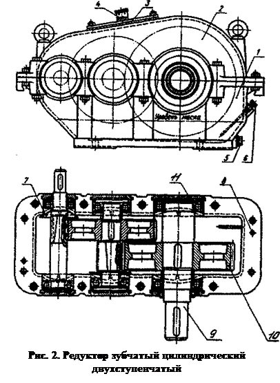 Gear strehimit është kryer më shpesh nga të hedhura e gri forcë të mesme hekuri MF dhe MF 15-32 18-36, ingranazhet dhe boshte - bërë prej çeliku strukturore. Shtëpitë e marsheve me distancë interaksile të fazës së ngadalshme me shpejtësi deri në 160 mm mund të hedhen nga aliazh alumini ALII.
Rrotat e dhëmbëzuara 10 lidheni me boshtin 9 përmes dowels - shufra prismatike, me pykë ose segmentuar, nyjeve të shpuara - vendosur uniforme përgjatë perimetrit të sipërfaqeve cilindrike të boshtit dhe nyjën e groove dhe zgjatimeve.
Heshta mbështet janë kryer duke përdorur kushinetat e rrotullimit (top dhe rul) ose gabim .
Qëllimi i mbështetësve - mbajini pjesët rrotulluese në pozicionin e duhur për funksionim korrekt pozicion. unaza e brendshme duke mbajtur janë shtyrë mbi bosht me një përshtatje ndërhyrje, dhe unaza e jashtme, mating me anëtarin stacionare - të gear strehimit, montuar me një pastrimin e vogël (apo ndërhyrje më të vogël se unazën e brendshme).
Instalimi i unazës së jashtme që mban për rrëshqitje përshtatje (me pastrimin e përshtatje) lejon unazë të rrotullohen gjatë operacionit, i cili siguron një veshin më uniform të pistat.
Në kutitë e shpejtësisë së përgjithshme, lubrifikim i kombinuar (lubrifikimi i karrexit). Një ose më shumë marshin janë lubrifikuar me ulje në një tretësirë lubrifikant lëngshme në pjesën e poshtme të kutisë veshje (strehim të) dhe njësitë e mbetura dhe pjesët, duke përfshirë kushinetave, lubrifikuar për shkak të spërkatur rrota vaj i zhytur dhe qarkulluese brenda strehim të formuar mjegull vajit. Në kohë është lubrifikim i vazhdueshëm. Lubrifikimi i karrexit përdoret në shpejtësitë rrethuese të rrotave të zhytur në m / s.
Thellësia e ingranazhet degëzuese zhytje vendosur jo më shumë se (0,8-1,5) -Step martesës, por jo më pak se 10 mm. Në shpejtësi të ulëta, p.sh. në fazat e ngadaltë e gearboxes multistage pranueshme thellë (rrezja rrota të 1/3) timon ulje.
Përafërsisht vëllimi i vajit në banjë mund të merret brenda (0.3 ... 0.7) 10 -3 m 3 për 1 kW të fuqisë së transmetuar.
Kur mbushjen crankcase lubrifikimit te marshit strehim filtruar vaj prodhohet me anë të një kurdisje ose hapjen e mbyllur me nje tape filetuar - nje dalje e cila gjithashtu siguron një brendshme mesazhin e strehim me atmosferën, parandalimin e shfaqjes së presionit të tepërt brenda mbyllje vakum ose kur ndryshon temperaturën e transmetimit. Tapë - ndenja është e vidhosur drejtpërsëdrejti në zorrë në pjesën e sipërme të tij ose në kapakun e çadrës së montuar.
nivelin e vajit dhe kontrollin operacioni karburantit është kryer duke përdorur Treguesit Niveli: transparente, zhezlovyh, tuba test me cilindrike ose konike temat dhe të tjerët.
Meqë niveli i lejuar i naftës në gearbox mund të jenë të ndryshme në një masë shumë të kufizuar nga të naftës matës transparente më të përshtatshme për t'u përdorur rrumbullakët. Ato janë kompakte, të lehta për t'u prodhuar, por për shkak të ndotjes në to me kalimin e kohës, dukshmëria e nivelit zvogëlohet. Në shufrën e matësit të vajit ekzistojnë rreziqe që tregojnë nivelin e sipërm dhe të ulët të vajit në karburanti. Ndonjëherë matësit shërbejnë si një zbrazje në të njëjtën kohë.
Kornizat me fileta të madhësive të mëdha përdoren si prizat e kullimit. mbyllja e vrimës së kullimit. Ato janë të vendosura drejtpërdrejt në pjesën e poshtme të strehimit, kështu që sedimenti gjithashtu bashkohet me vajin. Temperatura maksimale e vajit në kutitë e marsheve nuk duhet të kalojë 95 ° C.
Për lubrifikim individual të komponentëve, për shembull, përdoren lubrifikantë të naftës.
Për të parandaluar rrjedhjen e lubrifikantit nga kutia e shpejtësisë ose për ta kryer atë në formën e mjegullës dhe splashes së vajit, përdoren materiale dhe pajisje të ndryshme nënshkrimi. Lidhësit e mbulesës së përbërë (mbulesa e strehimit) janë të vulosura me pompa të veçanta të aplikuara në aeroplanin e lidhësit para se montimi i banesës. Në nyje flanged, materialet e rondelë me fletë të buta mund të përdoren gjithashtu.
Aktualisht, nënshkrimi i nyjeve të nyjeve është përdorur gjerësisht (GOST 9833) në formën e unazave të gomës me seksion kryq rrethore.
Për të vulosur pikat e daljes nga strehimi bosht me një diametër prej 6 ... 500 mm, vulat e buzëve të gomës (GOST 8752) janë përdorur gjerësisht. Krahët pengojnë që vaji të shpëtojë nga strehimi dhe të parandalojë që pluhuri dhe lagështia të hyjnë nga jashtë. Korniza metalike në formën e një burimi e bën pranga të ngurtë dhe lejon një përshtatje të ngushtë dhe të hermetikisht të ulur në shtresë. Buzët nënshkrimin janë ngritur kundër bosht për shkak të forcës elastike prej gome dhe llastik çorapesh pranverë e cila është e vendosur në brazdë dhe jakë është një pranverë konvencionale spirale me skajet ndërlidhura. Anther mbron buzë të punës nga pluhuri dhe papastërtia. Krahët e këtyre llojeve mund të punojnë në shpejtësinë rrethuese të boshtit në buzë të punës të prangave deri në 20 m / s.
Në praktikë përdoren edhe lloje të tjera të nënshkrimit të boshtit: me ndihmën e unazave të ndjerë të gjëndrave, vulave të fytyrës me disqe presioni, vula labirinti,
Lloji dhe informacioni i përgjithshëm për kutinë e shpejtësisë regjistrohen në tabelën e raportit të raportit laboratorik (Shtojca 1).
3. Përcaktimi i parametrave të një reducer gear cilindrik (të dhënat fillestare jepen në Shtojcën 4).
1. Përcaktimi i parametrave të ingranazheve.
Parametrat Përcaktimi nxisë () dhe angazhimi spiral makinë me pakorrigjuar (zero-offset) dhe me lartë rritje korregirovat (ravnosmeschennoe) mund të kryhet në sekuencën e mëposhtme:
1.1. Matur me përmasat e kalterit ![]() (Figura 3) dhe përcaktojnë distancat ndër-boshtore të transmetimit të parë (me shpejtësi të lartë) dhe të dytë (ngadalë):
(Figura 3) dhe përcaktojnë distancat ndër-boshtore të transmetimit të parë (me shpejtësi të lartë) dhe të dytë (ngadalë):
 Nëse vlerat e u janë afër vlerave standarde (Tabela 1), atëherë ato janë të rrumbullakuara në vlerat standarde. Modulet e fundit të ingranazheve janë përcaktuar.
Udhëzime metodike
në numri i punës së laboratorit 5
në detajet e makinave për studentët
specialitete të ndërtimit të makinerive
të gjitha format e arsimit
Nizhny Novgorod 2006
hartuesit AA Ulyanov, L.T. Kryukov, M.N. Lukyanov
UDK 621.833: 539.4 (075.5)
Përcaktimi i parametrave bazë të një reducer gear gear: Metoda. udhëzime për punën laboratorike № 5 në detajet e makinave për nxënësit e specialiteteve të ndërtimit të makinës. të gjitha format e trajnimit / NSTU; Hartuar nga: А.А. Ulyanov, L.T. Kryukov, M.N. Lukyanov - N. Novgorod, 2006. - 19 f.
Bëhet në përputhje me Enjoy 2.105-95 ESKD dhe STF-1 U-NSTU-98 për dokumente të përpunimit tekst për produktet inxhinieri.
Redaktor shkencor NV Dvoryaninov
Nënshkruar për të printuar formatin 60х84 1/16. Letër gazete.
Shtypjen offset. Pecs. l. 1.25. Uch.- ed. l. 1.2. Qarkullimi. urdhër
Universiteti Teknik Shtetëror i Nizhni Novgorod.
Shtypshkronja NSTU, 603600, N. Novgorod, rr. Minin, 24.
© Universiteti Shtetëror i Nizhny Novgorod
universiteti Teknik, 2006
1 QËLLIMI I PUNËS SË LABORATORIT
Qëllimi i kësaj pune për studentët është
- studimi i dizajnit,
- përcaktimi i parametrave kryesorë,
- marrja e shkathtësive të disassembly, rregullimit dhe montimit
reducer gear.
2 INFORMATA SHKURTËR NGA TEORIA
2.1 reducer është thënë se një ose më shumë marshin (krimb) veshje, të vendosura në një strehim të mbyllur me nje vaj-banjo dhe prednaz vlerat për uljen e shpejtësisë kendore dhe rritja e momentit rrotullues në bosht prodhimit.
Faza e marshimit- një transmetim që lidh dy boshte ngjitur.
Gearbox aktuale - Transmetimi që transmeton një rrymë të fuqisë.
2.2 Në formën e saj më të përgjithshme reducer gearduhet të ketë:
- ingranazhet e ingranazhit (ingranazhet dhe rrotat), boshtet, mbështetësit boshtor (kushinetat);
- një sistem për rregullimin e lidhjeve dhe "luajtjen axial" të boshteve (pastrimi në kushineta);
- trupi dhe mbulesa me mbajtëset dhe kunjat për të rregulluar pozicionin relativ të trupit dhe të mbuluar;
- sistem lubrifikimi me elemente për derdhjen, monitorimin dhe kullimin e vajit;
- vulat e lidhjeve, fundeve të hyrjes dhe daljes së boshtit;
- pajisje për baraspeshimin e presionit brenda shtëpisë (ndenja);
- pajisje për transport (bulona, syze, grepa, etj.
2.2.1 Në kutitë cilindrike, ingranazhet spirale. Dihet rrota me një numër më të vogël dhëmbësh zinxhir z 1, me një numër të madh dhëmbësh - rrota z 2 .
Në boshtet e ndërmjetme, drejtimi i dhëmbëve të ingranazhit dhe rrotat duhet të përputhen (për të kompensuar veprimin e forcave boshtore). Megjithatë, në prodhim në masë dhe në shkallë të gjerë, pajisjet për prodhimin e marsheve janë të specializuara dhe të akorduara për prerjen e dhëmbëve të rrotave z 2 të gjitha nivelet me pjerrësia e duhur, dhe rrota gear z 1 - me majtas. Në këtë rast, forcat axial janë shtuar së bashku në angazhim, duke rritur duke mbajtur ngarkesën, por një "shkelje teknike" në prodhim në masë jep përfitime të mëdha ekonomike, duke ulur koston e produktit duke reduktuar kompleksitetin e prodhimit pa kalim.
2.2.2 Si në njësitë e veshje të plotë-shkallë në këtë laborator, vlera aktuale kompensuar nga koeficientët në angazhimin janë të panjohura, ky i fundit do të përcaktohet vetëm nga gjendja e mungesës së shkurtimin e dhëmbëve, dhe transferimi do të jetë KUSHTËZUARravnosmeschennoy.
Parametrat bazë ingranazhet spirale të marsheve të jashtme:
1) numri i dhëmbëve z 1 dhe z 2, numri i tyre i përgjithshëm z S = z 1 + z 2 ;
2) raportet e marshave:
- hapat u = z 2 / z 1: - me shpejtësi të lartë u B dhe me lëvizje të ngadaltë u T;
- reducer i përbashkët u 0 = u B u T;
3) Largësia ndërmjet akseve një W = 0,5 z S m n/ cosb (2.1)
4) Gjerësia e ingranazhit të unazës b. Gjerësia e punës së kurorës b W = b 2 ;
5) koeficienti i gjerësisë së punës së kurorës mbi distancën qendrore
y ba = b W/ një W;
koeficienti i gjerësisë së punës në diametër fillestar të marsheve d W 1
y bd = b W/d W 1 ose y bd = 0.5y ba(u + 1).
6) Moduli i angazhimit m = p/ p, ku r - katran e dhëmbëve përgjatë harkut të rrethit të ndarjes.
Vlerat standarde një W, u, y ba për ingranazhet cilindrike me ingranazh të jashtëm në përputhje me GOST 2185 - 66 janë dhënë në kërkesëA.1; module normale m në përputhje me GOST 9563 - 60 - in kërkesëA.2.
Nëse matemi një W, z S dhe gjeni cosb ¢ (shih më poshtë, § 5.7), pastaj me formulën (2.1)
përafërsisht mund të përcaktojë modulin normal m n:
m n¢ = 2 një W cosb ¢ / z S, (2.2)
me radhitje atë në vlerën standarde m, përkatëse m n.
7) Parametrat e konturit fillestar të ingranazheve cilindrike - sipas GOST 13755-81:
këndi i profilit a = 20 0; lartësia e dhëmbit h a= h a*m, ku h a* = 1; lartësia e dhëmbit orë = 2,25 m ; pastrimin radial në angazhim me = 0,25 m .
8) Pasi moduli është i rrumbullakosur, vlera e këndit të pjerrësisë së dhëmbëve përcaktohet nga formula (2.1) b:
b = arkivat (0.5 m z S / një W) . (2.3)
Për dhëmbët e zhdrejtë [b] = 8 ... 18 0.
Këndi i përçarjes profili në pjesën fundore
një t = arctg (tg20 0 / cosb). (2.4)
Këndi kryesor i dhëmbit
b b = arcsin (sinbcos20 0). (2.5)
9) numri i dhëmbëve të pajisjes duhet të kontrollohet për mungesën e prerjes së këmbës së dhëmbit sipas formulës z 1 ³ z 1 min = 17 cos 3 b.
Nëse ky kusht nuk është plotësuar, llogarisni faktorin e paragjykimit x 1 kur preren dhëmbët e ingranazhit x 1 = 1 – z 1 / z 1 min nën kushte z 1 < z 1 min dhe x 1\u003e 0. Nëse z 1 ³ z 1 min, pastaj në këtë laborator kushtimisht
duhet të miratojë x 1 = 0.
Në ingranazhet spirale dhe zhurnale për vlera të vogla z 1, rekomandohet korrigjimi i lartësisë së dhëmbëve; x 2 = – x 1 dhe x 1 + x 2 = 0.
10) diametra të qarqeve (për x 1 + x 2 = 0), mm:
- ndarjen d = mZ / cosb; (2.6)
- fillore d W 1 = 2një W / (u + 1) , d W 2 = d W 1 u ; (2.7)
- vertices d a = d + 2m(1 + x) ; (2.8)
- depresionet d f = d – (2,5 – 2x)m ; (2.9)
11) shpejtësia rrethuese e rrotave të mjeteve v = f d W n / (6 × 10 4), m / s, (2.10)
ku n - shpejtësia e marsheve, min -1.
2.2.3 Për transmetimin e çift rrotullimit midis boshtit dhe rrotave, dowels, lojëra elektronike, këmbët dhe ulje me ndërhyrje të garantuar.
pinions, si rregull, të kryejnë në një copë me bosht. rrota - I lëvizshëm.
Mbërritjet e hyrjes dhe daljes së boshtitkryeni koniknë përputhje me GOST 12081 - 72 (të preferuar) dhe cilindrik Sipas GOST 12080 - 66.
2.2.4 Ashtu si kushineta boshtperdorni kushinetat e rrotullimit. Në lidhje me rritjen e ngarkesave dhe këndeve të pjerrësisë së dhëmbëve në kutitë cilindrike me qëllim të përgjithshëm, gjithnjë e më shpesh kushineta topin e kontaktit me rrotull tapered këndore.
Sistemi i konceptimeve konvencionale të kushinetave të rrotullimit është themeluar nga GOST
3189 - 89 dhe është përshkruar në detaje në udhëzimet për puna laboratorike№ 10 .
Në reducers cilindrik - boshte i shkurtër; mbështetëset e fiksimit në një anë; skema e instalimit të kushinetave në boshte - "Vraspor".
2.2.5 Në ingranazhet cilindrike angazhim posaçërisht nuk rregulloni. Për të kompensuar gabimet e prodhimit dhe montimit në drejtimin axial, b 1 > b 2. Rregulloni hapësirat në kushineta, duke siguruar kur bashkohen "luaj axial" i boshtit. " Lojë aksiale"- është e pranueshme-Mye rritje bosht aksiale pastrimin e plotë me kushineta e nevojshme për funksionimin normal të nyjeve dhe të përgjegjshëm të mëvonshëm deformim temperaturë pune (mostër GAP).
Rregullimi i "lojës axial" (Hapësirat në kushineta) të veprojë me anë të shims, bluara unaza, arra unazë me washers Multiwing, vidhos pullat, burimet dhe të tjerët. Aktualisht, boshllëqet në kushineta rul tapered në instalimin e tyre "vraspor" të kontrolluara rregullatorët e vidë (Figura 1).
Në figurën 1 tregohet: 1 - bosht; 2 - mbajtja; 3 - strehim reducer
4 - një rondele për shtyp; 5 - Kapaku i montimit të montimit me gjilpërë metrike (M d x p); 6 – rregulluar vidhe, i dehur në kapak me një çelës të veçantë nëpërmjet vrimave 7 në vidë; 8 - bllokimi nga vetërheqja e vidës 6.
Figura 1 - Rregullatori i vidës "luaj axial"
Gjatë një rrotullimi të vida 6 (0 360) dhe rondele 4 me duke saj unazën e jashtme 2 janë lëvizur në drejtimin aksial nga sasia fushë fije e r. Nëse vidhja ka n vrima 7, atëherë rotacioni minimal i mundshëm do të jetë në një kënd g = 360 0 / n, e cila korrespondon me lëvizjen aksiale të rregullatorit (rondele) në p / n. Nga këtu përfundim : Sa më i vogël të jetë katran r dhe më shumë vrima n (dmth., diametra d dhe d 0), aq më i lartë "ndjeshmërinë" e kontrollues dhe vlerë më të vogël të mundshëm (saktësisë më të lartë) të Rregullores axial hendekut.
2.2.6 Në prodhimin në masë dhe në shkallë të gjerë strehim dhe mbulesëkutitë e marsheve janë prodhuar injeksion prej gize, çeliku ose silogji; në një prodhim të vetëm dhe në shkallë të vogël, si rregull, saldim nga çeliku i mbështjellë.
Thjeshtësitë mbi pjesët e trupit në zonat e mbajtjes quhen bosët. Bazat mbështetëse në pjesën e jashtme janë të mbyllura me mbulesa, të cilat mund të jenë lart (i dehur në trup dhe në kapakun e marsheve) dhe prerje (ata janë ngulitur në zakonin e pjesëve të trupit). Kufizimet e farkëtimit janë më moderne dhe më të preferuara. Rregullatorët e vidave vendosen në mbulesa (Figura 1).
Protrusions për fasteners në rritje, bordurë trupit dhe të mbuluar në lidhës e tyre, janë quajtur fllanxhat. Prerjet për bashkimin e trupit me kornizën (pllakën) e makinës quhen putrat.
Në bulonat, fllanxhat, kunjat, vendosni vidha ose bulona. Klasa forca e bulonave duhet të jetë të paktën 6.6. Në fllanën e trupit, një vrimë e filetuar është siguruar për rrotullën e shtrydhjes.
Si rregull, mërzitja përfundimtare e vrimave për kushineta është bërë në një instalim në njërën anë me një barbell me prerëse. Para vrimës së fllanxha bos dhe shtrëngimin bulonat (vida), pas së cilës trupi dhe kapaku janë të fiksuara nga dy kunjat (rregulluar diagonalisht) është montuar në makine dhe prodhimin e vrimave të kalibër e të gjithëve boshte. Këmbët sigurojnë që saktësia e mërzitjes së vrimës mbetet e njëjtë pasi kutia e shpejtësisë të jetë disassembled dhe montuar. Preferohen këmbët konike.
Në kapak kryer eyelets për transportin mekanik të reducers. Dhe në reducers rëndë - edhe grepa në flanges e hulls.
2.2.7 crankcase (me zhytje) vajosje rrotave përdoren me shpejtësi rrethuese v nga 0.3 në 12.5 m / s. M viskoziteti i rekomanduar i vajit për ingranazhet e çelikut në varësi të streseve s H dhe shpejtësia v
Listuar në kërkesë B.
Parimi i klasës së naftës: sa më i lartë është shpejtësia v, aq më e ulët është viskoziteti i kërkuar m, dhe sa më i lartë është s tensionit H , aq më i madh është viskoziteti m.
Për kutitë e transmetimit në dy faza, zgjedhja e m është bërë në bazë të vlerave mesatare të s H m dhe v m hapa me shpejtësi të lartë dhe me shpejtësi të ulët.
1) Dhe - industriale;
2) Г - për sistemet hidraulike; A - nyjet e ngarkuara lehtë; T - nyjet e ngarkuara rëndë;
3) grupi i performancës: A - vaj pa aditiv; C - vaj me aditivë antioksidues, antikortozë dhe antiwear, etj;
4) klasa kinematike e viskozitetit m.
Për shembull, vaj И-Г-А-46, ku 46 - viskoziteti mesatar kinematik m, mm 2 / c, në 40 0.
Nivelet e lejuara të zhytjes së rrotave të një kutie cilindrike në një dush të naftës orë M i 2 m deri në 0,25 d 2 T).
Besohet se në një transmetim me dy faza me v ³1 m / s është e mjaftueshme për të zhytur në vaj vetëm rrota e fazës së lëvizjes së ngadalshme. në v < 1 м/с в масло должны быть погружены колеса обеих ступеней редуктора.
Minimumi i kërkuar vëllimi i naftës për lubrifikim të ingranazheve V min = (0,3 ... 0,7) litra për 1 kW të fuqisë së transmetuar (mesatarisht V min = 0.5 Pl / kW, ku P - reducer). Vëllimi aktual i naftës V Në mbajtësen e crankeve përcaktohet nga përmasat e brendshme të dushit të trupit L BH, Në VN dhe niveli i vajit (lartësia) H M në të ( V = L BH x Në BH x H M dm 3; 1dm 3 = 1L). Gjendja V > V min.
Me shpejtesi te rrotave v \u003e 1 m / s kushineta lubrifikuar razbryz-shtrëngim vaj karburanti. Me një shpejtësi më të ulët përdoret yndyrat.
Nafta derdhet përmes sheshit të inspektimit ose vrimës, të mbyllur me një ndalje të ndaluar, në kapakun e reducer. Drain oil - përmes vrima me ndalues në fund të strehimit.
Kontrolli i nivelit të vajit kryhet nëpërmjet prizave të kontrollit, sondave, përmes qelqit etj.
2.2.8 Në mënyrë për të parandaluar rrjedhjet e naftës nëpërmjet boshllëqet në input dhe output boshte të aplikojnë cik (Enjoy 8752-79), Allen, slotted, Labyrinth, etj vulë.
Për të nënshkruar avionin e lidhësit të strehimit dhe të kapakut para asamblesë përfundimtare ata janë të mbuluar me një shtresë sealant UT - 34 GOST 24285-80.
2.2.9 Në varësi të pozicionit relative të boshteve boshtore, numri i boshteve që largohen nga strehimi (nga 2 në 4) dhe orientimi i tyre në përputhje me GOST 20373-94 janë të instaluar opsionet e montimit reducers, të cilat janë dhënë në kërkesë A3.
2.2.10 Shembull i emërtimit cilindrike me dy faza reducer ngushtë me distancë të largët të fazës së ngadaltë-shpejtësi një W T = 200 mm, raporti total i ingranazhit u = 25 0, 12 dytë mishërim e grumbullimit, me fundin konike të bosht të prodhimit - K, ekzekutimin klimë Y (klimë të butë), 2 kategori vendosje GOST P 50.891-96:
REDUCTOR Ц2У - 200 - 25 - 12К - У2 ГОСТ Ј 50891-96.
E njëjta gjë për një kuti me një fazë me një W = 160, u = 3.15, kuvendi 22:
REDUCTOR TU - 160 - 3,15 - 22K - U2 GOST R 50891-96.
3 OBJEKTI DHE MJETET E EKZEKUTIMIT TË PUNËS
Objektivat e analizës janë kutitë cilindrike me një ose dy faza të prodhimit industrial të skemave të ndryshme kinematike dhe versioneve të projektimit.
Për të kryer punën në laborator, mësuesi lëshon një kuti të veçantë, punime metali dhe mjete matëse, literaturën e nevojshme metodologjike dhe referencat.
Për llogaritjet, studenti duhet të ketë një llogaritëse dhe të regjistrojë rezultatet - një formë standarde e "Raportit".
4 MBROJTJA E PUNËS
Rregullat e përgjithshme për sigurinë dhe sanitetin industrial për punonjësit dhe studentët e departamentit janë përcaktuar në udhëzime № 289.
Për këtë punë, duhet të theksojmë:
1) Reduktuesit dhe pjesët e tyre, si rregull, kanë masa të rëndësishme;
2) Kur lëvizni ose riorganizoni njësinë e ingranazhit, sigurohuni që bulonat e bosëve, flanxheve dhe kapakëve të mbajtjes të jenë të shtrënguara. Për skajet e boshteve, mos e ngrini reducer. Ju mund të hiqni flanxhat e rastit;
3) mos thoni gishtat tuaj në hendekun e avionit të lidhësit midis kapakut dhe trupit, në ingranazhet;
4) pjesët e hequra të reducer (mbulon, boshte, rrota, etj) duhet të jetë fikse dhe fikse të sigurt në planin e tabelës;
5) kur zhbllokohet, fiksoni fasteners në një vend;
6) pas montimit të reducer, boshtet duhet të rrotullohen lirisht me dorë, nuk duhet të ketë pjesë të "rezervuara"; bulonat duhet të shtrëngohen me çelësa;
7) informoni menjëherë mësuesin për lëndimin kur plagoseni.
5 RENDI I PERFORMANCËS
5.1 Në një shkallë arbitrare, por me përmasa themelore,
vizatoni skicën e kutisë së transmetimit të dhënë në 2 projeksione. Një shembull është paraqitur në Figurën 2.
5.2 Për artikujt në Tabelën 1 të "Raportit" (shih par. kërkesë B) matni dhe regjistrojnë dimensionet e përgjithshme dhe lidhëse të reducer. Tregoni ato (në shifra specifike) në skicën e marsheve (Figura 1 në " raportPër referencë, të gjithë parametrat e Tabelës 1 tregohen me shkronja në Figurën 2. Për dizajnet specifike të kutisë së shpejtësisë, ato mund ose nuk mund të modifikohen.
5.3 çmontimit dhe të inspektojë pajisjen gear e pjesëve të saj, me vëmendje të veçantë për të hartuar përmban ingranazhet, boshte, kushineta, pullat, housings, mbulon, pjesë e sistemit të naftës, vula, etj
5.4 Matni bulonat e montimit (vida) dhe u jepni një përcaktim standard.
5.5 Në figurën 2 të "Raportit", kryeni skemën kinematike të kutisë së shpejtësisë në përputhje me GOST 2.770-68 ESKD.

5.6 Klasifikoni kutinë e marsheve sipas pikave të specifikuara në kërkesë V.
5.7 Përdorimi i drejtimeve dhe formulat e 2.2.2, përcaktojnë parametrat kryesore të ingranazhet dhe ingranazhet në rendin e treguar në Tabelën 2 apps B. Për një reduktues me një fazë të grafikut "Rezultat" të Tabelës 2, duhet të jenë të pranishëm vetëm dy kolona ( z 1 dhe z 2). Në kolonën "Shënim", tregohet mënyra e përcaktimit të një parametri (sipas matjes ose llogaritjes). Matjet duhet të bëhen me saktësinë më të madhe të arritshme.