Angrenajul principal este format din angrenajele de antrenare și de antrenare. Angrenajul pinion este instalat în carcasa angrenajului pe două rulmenți conice. Între inelele interioare instalate manșon distanțier 3160-00-2402029-00 . O flanșă este montată pe gamba angrenajului pinionului. Este atașat la coadă printr-o piuliță autoblocantă. Între fața finală a angrenajului pinion și inelul interior rulment spate este instalat un inel de reglare care definește poziția corectă angrenajul de antrenare în raport cu angrenajul condus. Acest inel are o grosime diferită de la 2,55 la 3,55 mm. la fiecare 0,05 mm. Șaptesprezece dimensiuni ale unui inel de reglare asigură reglarea exactă a unui aranjament relativ al angrenajelor transferului principal.
Pentru a preveni deplasarea axială a angrenajului în sarcini de lucru, în lagărele sale se creează o preîncărcare prin strângerea piuliței. În acest caz, se produce deformarea.
manșon distanțier 3160-00-2402029-00 la o anumită limită. Mărimea potrivirii interferenței a rulmenților este controlată de un dinamometru prin momentul de rezistență la rotirea angrenajului pinionului. Momentul trebuie să fie egal cu 16-20 kgf / cm pentru rulmenții noi și 4-6 kg / cm pentru rulmenți după o alergare de 30 km sau mai mult.avertisment: la repararea cutiei de viteze puntea fata trebuie să instalați o nouă manșon distanțierdacă lagărele cu pinioane au fost înlocuite
Pentru a verifica momentul de rezistență, puneți dinamometrul pe manșonul adaptorului, setați indicele limită de cuplu pe diviziunea de scară, corespunzătoare a 20 kgf / cm și folosiți mânerul pentru a face mai multe rotiri în sens invers acelor de ceasornic. În timpul rotirii angrenajului pinion, indicatorul mobil nu trebuie să depășească indicatorul montat pe scară și ar trebui să arate cel puțin 16 kgf / cm.
Dacă momentul de rotație de rotație este mai mic de 16 kgf / cm, iar pentru rulmenții de 30 km sau mai mult - 4 kgf / cm, strângeți piulița flansa a angrenajului pinionului și verificați din nou momentul de rotație al pinionului.
Dacă momentul de rotație de rotație s-a dovedit a fi mai mare de 20 kgf / cm, iar pentru rulmenții de rulare de 6 kgf / cm, ceea ce indică o preîncărcare excesivă a rulmenților, înlocuiți manșonul distanțier, deoarece a fost deformat de la sarcină excesivă la o dimensiune care nu permite ajustarea corectă. După înlocuire manșon distanțier reasamblați cu ajustări și verificări adecvate.
Puntea din spate: 1 - o carcasă; 2 - angrenaj condus angrenaj principal; 3 - o roată dințată care conduce transferul principal; 4 - rulment spate; 5 - rulment frontal; 6 - inel; 7 - o flanșă; 8 - o piuliță; 9 - șaibă; 10 - manșetă; 11 - manșon distanțier; 12 - un inel de reglare; 13 - dop de umplere; 14 - rulment diferențial; 15 - axa dreapta; 16 - supapă de siguranță; 17 - piuliță portantă diferențială; 18 - un șurub; 19 - o placă de blocare; 20 - șaib de împingere; 21 - o copertă a unui caz; 22 - diferențial; 23 - un șurub; 24 - așezare; 25 - axa stângă; 26 - inel de reglare; 27 - un șurub; 28 - capacul rulmentului diferențial; 29 - inel de ulei
Cunoscând dispunerea mecanismelor și elementelor care alcătuiesc osia de antrenare, considerăm dispunerea axelor de acționare spate în schema de transmisie clasică
1. AXILE DRIVE SPATE CU ROȚI DE SUSPENSIE RIGIDĂ
Osii de antrenare rigide cu acțiune finală cu o singură etapă.
În fig. 6.1-6.11 prezintă axe de conducere cu o suspensie rigidă a roților, realizată pe baza schemei prezentate în Fig. 1.2, a.
Mașină „Varșovia“. Proiectarea axei de antrenare a vehiculelor din Varșovia de la modelele 202, 203 și 223 este un exemplu tipic de design clasic al osiei de antrenare cu un carter rigid (Fig. 6.1). carterului puntea spate constă dintr-o capacă și carcasa reală, interconectate de șuruburi. Ambele părți sunt turnate din fontă maleabilă cu o duritate de HB 121-249. Mânecele sunt introduse în carter și capac, apoi mânecile din țevi de oțel. Flanșele (forjate din oțel 45) sunt sudate la capetele exterioare ale mânecilor, la care sunt atașate discurile de frână. Pernele cu arcuri sunt sudate și pe mânecile Semiconductoarele flanșate ale punții spate de tipul semicarcat sunt confecționate din oțel de 35 HGS cu duritatea HRC 30-35. Rulmenții cu bile ale semiaxurilor percep transversal și sarcini axiale. Tamburul de frână și roțile sunt atașate direct de flanșa axului.
Rulmentul cu bilă al fiecărei axe este montat pe un inel de oțel 45, prevăzut cu o fixare de interferență ridicată și întărit superficial la punctul de contact cu sigiliul până la o adâncime de 1,5-2 mm până la o duritate de HRC 45. O șaibă elastică din oțel este plasată între inelul de montare și inelul interior al rulmentului 60G duritate HRC 40-45 și eliminarea spațiilor axiale axiale. Rulmenții de osie sunt lubrifiați cu grăsime prin fitinguri de grăsime. penetrație lubrifiant sigiliile împiedică frânele să intre în interior.
Pentru a reduce presiunea în interiorul punții spate, care crește în timpul funcționării sub influența creșterii temperaturii, se folosește o supapă de aer.
Fig. 6.1. Hard ^ puntea de tracțiune spate a mașinii Warsaw-223
Mașină Fiat-125R . În fig. 6.2 prezintă puntea de acționare spate folosită în mașina Fiat-125P. O descriere a angrenajului principal și a diferențialului este prezentată în cap. II. Sumpul dur se face ca o singură unitate. Semiaxele de tipul semi-descărcate sunt montate pe rulmenți cu bile, iar rulmenții sunt fixați prin inele montate cu interferențe.
Mașina Moskvich-412 . Puntea spate se bazează pe o carter, formată din două jumătăți (superioară și inferioară), ștanțată dintr-o foaie de oțel grosime de 3,4 mm și sudată împreună cu două cusături longitudinale (Fig. 6.3). Capetele carterului sunt sub formă de țevi, la suprafețele de capăt ale căror două flanșe de oțel forjate sunt sudate cu o sudură cu fund. În ele sunt ștanțate cuiburile pentru rulmenții și sudurile pentru șuruburile de fixare disc de frână. În apropierea flanșei, două perne sunt sudate pe carter pentru fixarea arcurilor din spate.
Partea de mijloc a carterului este extinsă și are o gaură mare pentru instalarea angrenajului principal. Pentru a crește rigiditatea flanșei acestui orificiu, o sudură este sudată la ea. Gaura din spate este închisă de un capac sudat convex stampilat în care sunt amplasate părțile proeminente ale transmisiei. Descrierea reductorului principal și a diferențialului automobilului Moskvich-412 este plasată în sec. II.
Axele 6 ale punții spate sunt realizate din oțel carbon. La capetele exterioare ale osiilor sunt prevăzute flanșe la care sunt atașate tamburele și roțile. Capetele interioare ale semiaxurilor au spline involute care intră în orificiile despicate ale angrenajelor axelor diferențiale. Un singur rând pe semi-axă cu interferențe rulmenți cu bile <9, закрепленные с помощью втулок 5, установленных на полуоси с натягом. Наружное кольцо подшипника 3 расположено в выточке фланца 17 картера 8 заднего моста и закреплено с помощью пластины 19 , прикрепленной к фланцу четырьмя болтами 24. Между внутренним кольцом подшипника и фланцем* полуоси установлена дистанционная втулка 22. На эту втулку установлен фетровый уплотнитель, предохраняющий подшипник от пыли и грязи, а также предотвращающий проникновение смазочного материала подшипника на барабан и колодки тормоза. Однако войлочное уплотнительное кольцо не могло бы удерживать жидкого гипоидного масла, если бы имелся свободный доступ от картера к подшипнику. Поэтому с внутренней стороны подшипника размещен резиновый самоподжимной сальник 4 на шлифованной поверхности втулки 5. Подшипник смазывается пластическим смазочным материалом через масленку 18.
Din exteriorul inelului 23, un disc deflector 21 este atașat la discul de frână, care protejează tamburul și plăcuțele de frână de ulei în cazul unei scurgeri în inelul o. Pe semiaxis, în apropierea flanșei sale, există un inel conic din care uleiul scurs este aruncat prin forță centrifugă pe suprafața exterioară a deflectorului de ulei și astfel nu este permis să lovească tamburul de frână.

Fig. 6.2. Puntea de antrenare spate a mașinii Fiat-125R

Fig. 6.3. Puntea de antrenare spate a mașinii Moskvich-412:
I - disc de frână la roată; 2 - cilindru de frână; 3 - rulment cu bile cu jumătate de axă; 4 - un epiploon intern al unei semiaxis; 5 - manșon rulment; 6 - axul axei; 7 - pernă de primăvară; 8 - carcasa punții spate: 9 - respirație; 10 - frana hidraulica tee;
II - amplificator carter; 12 - un caz al transferului principal; 13 - o căptușeală; 14 - o copertă a unui caz; 15 - dop de umplere; 16 - conducta de frână hidraulică; 17 - flansa carterului; 18 - lubrifiant cu rulmenți 19 - o placă pentru fixarea capătului jumătății arborelui; 20 - tambur de frână; 21 - deflector de ulei; 22 - manșon distanțier; 23 - etanșarea arborelui osiei încărcate; 24 - un șurub de fixare a rulmentului și a discului de frână; 25 - șurub de montare a roților; 26 - orificiu de scurgere a uleiului
O gaură 26 este prevăzută pentru devierea acestui ulei în placa 19 și pe discul * 1 al dispozitivului de frânare.
Deflectoarele de ulei amplasate în carcasa punții spate împiedică uleiul să-l mute de la partea de mijloc a carterului la roți, sub influența forței centrifuge în timpul mișcării curbiline a mașinii. Consecința acestei revărsări ar fi o scădere a nivelului de ulei în angrenajul principal și notarea suprafețelor de lucru ale dinților angrenajelor hipoide.
Cu o mișcare prelungită a mașinii, în special în sezonul cald, angrenajul principal și diferențialul punții spate sunt încălzite. Pentru o punte de intrare, încălzirea la o temperatură de 80 ° C este normală și nu înseamnă o defecțiune a acesteia. Într-un pod nou, fără rulaj, această temperatură ajunge la 100 ° C. Un respirator de aer este amplasat pe carcasa punții spate din partea dreaptă (în Fig. 6.3 este convențional prezentat în partea stângă a podului și este indicat prin 9), care este o armătură cu un orificiu închis de o supapă. În afara robinetului este închisă cu un capac de protecție. Când puntea spate se încălzește, aerul în exces iese prin supapă. În caz contrar, presiunea în carter ar crește, ceea ce ar duce la scurgerea uleiului din carter prin garniturile de ulei ale arborelui osiei și ale transmisiei principale.
Între carcasa angrenajului principal și carcasa punții spate există o garnitură 13 din carton special cu o grosime de 0,5 mm. O garnitură din același material este plasată între placa 21, precum și între placa 19 și discul de frână 1.
Firma „Transmisie Salisbury”. În axa de acționare a modelului 4HA, se utilizează angrenaj hipoid, un diferențial conic convențional și axe semi-descărcate (Fig. 6.4). Deoarece semiaxa neîncărcată este montată pe un rulment conic, un cracker este instalat între suprafețele de capăt ale semi-axelor, transmitând forța axială de la o semi-axă la alta.
Mașină Cadillac Eldorado“. Axa spate prezentată în fig. 6.5, este o modificare a axului de tip Salisbury cu arbori de ax semi-descărcați, în care angrenajul de antrenare al angrenajului principal este susținut de un rulment cilindric și de două role. Reglarea spațiului lateral din angrenaj este simplificată prin utilizarea unor garnituri 4 între cupa portantă a angrenajului hipoid de antrenare și carcasa diferențială. Distanța din rulmenți este reglată independent de reglarea laterală (care nu a fost posibilă la modelele produse anterior) folosind piulița angrenajului principal al angrenajului principal comprimând distanțierul cu pereți subțiri situat între inelele interioare ale rulmenților conici.
Pentru a regla poziția angrenajului condus, au fost utilizate garnituri 2 între fața de capăt a inelului exterior și umărul carcasei diferențiale. Lagărele conice sunt reglate cu piulița de reglare 3 care acționează pe rulmentul diferențial drept.

Fig. 6.4. Axa de tracțiune din spate mod. 4YAL cu diferențialul standard al companiei de transport Salzbury

Fig. 6.5. Puntea de antrenare a Cadillac Eldorado (an model 1970):
1 - rulment conic cu design special (vezi fig. 4.8); 2 - tocuri pentru schimbarea poziției angrenajului condus al angrenajului principal; 3 - piuliță pentru reglarea interferenței lagărelor diferențiale conice: 4 - creșteri pentru schimbarea poziției angrenajului pinionului de antrenare final; 5 - deplasarea axei angrenajului de antrenare
Mașina este un Mercedes-Benz. Puntea rigidă de tracțiune din spate a magistralei 0303 are o tracțiune finală cu o singură etapă și un diferențial convenabil cu șanț (Fig. 6.6). Se folosesc osii complet descărcate, care se termină cu flanșe, la care butucurile roților sunt montate cu șuruburi, montate pe carter cu ajutorul unor rulmenți conici situați conform schemei 0.
Щ Mașină „Steaua 29” . Puntea rigidă de tracțiune din spate a camionului Star 29 are o tracțiune finală cu o singură etapă, cu dinți în spirală de tip Gleason și un diferențial convenabil cu șanț (Fig. 6.7). Carcasa osiei de antrenare tip banjo este consolidată cu două tuburi de susținere din oțel care servesc la instalarea lagărelor conice ale roților de antrenare. Semicercurile sunt complet descărcate.
Mașină „Steaua 200“. Axa hard disk-ului este prezentată în fig. 6.8. În carterul transmisiei principale, sunt instalate cu interferență conductele de susținere 2 ale carterului de punte, în plus consolidate cu nituri electrice. Pe două rulmenți conici 8 există un diferențial format dintr-o carcasă 3, două angrenaje de ieșire 4 și patru sateliți 5 montate mobil pe vârfurile păianjenului 6. Rulmenții diferențiali sunt montați în paranteze cu capacele 9 atașate de șuruburi 12. Diferențialul poate fi blocat folosind dispozitivul 23 fixat la

Fig. 6.6. Puntea rigidă de conducere spate a autobuzului Mercedes-Benz-0303
husa carterului. Aerul comprimat este furnizat dispozitivului de blocare format dintr-un cilindru, un piston 26, un arc 27 și un împingător 25 cu furci printr-o supapă electro-pneumatică controlată de un întrerupător amplasat pe panoul de instrumente în cabina șoferului. Sub presiune de aer, pistonul 26 mișcă împingătorul cu furculițele 25 și conectează pinii cuplajului 24 cu orificiile din arborele de viteze. Rotația angrenajului cu jumătate de axe în raport cu carcasa diferențială este imposibilă în acest caz, iar diferențialul este o singură unitate, prin urmare, roțile nu se pot roti cu frecvențe diferite (mișcarea curbilină nu este permisă, deoarece acest lucru va duce la răsucirea jumătății axei). Angrenajul principal cu un raport de viteză de 5.43 (38: 7) constă dintr-o pereche de viteze conice cu dinți spirali de tip Gleason. Angrenajul de antrenare 16 al angrenajului principal se cuplează cu treapta de antrenare 7, bolțată 15 la carcasa diferențială. Angrenajul pinion este montat pe două rulmenți conici și pe un rulment cu role în formă de butoi. Pe pârtiile arborelui angrenajului de conducere există o flanșă 22 pentru montarea arborelui de antrenare, sigilată cu două garnituri 21 introduse în capacul 20.

Fig. 6.7. Puntea rigidă de tracțiune spate a mașinii Star-29

Fig. 6.8. Puntea de tracțiune din spate a mașinii Star-200:

Fig. 6.9. Puntea rigidă de antrenare spate cu o treaptă principală în două trepte 2676 a companiei DAF, proiectată pentru o sarcină nominală de 127,5 kN (primul pas este un angrenaj hipoid, al doilea este un angrenaj elicoidal elicoidal)
Cuplul de la angrenajul principal este transmis roților de către semi-axe 29, ale căror spine involute sunt introduse în orificiile despicate ale angrenajelor axelor diferențiale. Flanșele de osie sunt fixate pe butucurile a 30 de roți cu ajutorul știfturilor 32 și piulițelor. Butucurile roților sunt montate pe două rulmenți conici 33 și 34, ale căror inele interioare sunt amplasate la capetele conice ale conductelor carterului. Pentru a regla etanșeitatea lagărelor conice ale butucurilor roților și pentru a elimina spațiile libere în timpul funcționării, se folosesc piulițele de reglare 35. Butucurile roților sunt sigilate de o glandă 38, sunt introduse în partea inferioară a butucului și interacționând cu inelul 37. Etrierile de frână cu suporturi pentru încălțăminte de frână sunt atașate la flanșele sudate ale carterului 36.
Axe spate rigide cu acțiune finală în două etape.
În fig. 6.9 prezintă o axă de tracțiune din spate rigidă cu o tracțiune finală în două etape, cu prima etapă realizată sub forma unui angrenaj hipoid, iar a doua sub forma unei angrenaje elicoidale. Un alt exemplu de proiectare a unei acționări finale în două etape a fost prezentat mai sus în Fig. 2.71.
Osii de antrenare rigide cu angrenaj distanțat în două etape.
Mașină UAZ-469 În vehiculul off-road UAZ-469 sovietic de utilitate și pasageri, a fost utilizată o axă de antrenare cu angrenaje interne de antrenare finale în roțile de antrenare. Carcasa principală (Fig. 6.10) este împărțită într-un plan vertical și este formată din două părți: carterul real 18 și capacul 2. În ambele părți ale carterului, ciorapii carterului sunt presate și fixate prin sudare la fața locului. Angrenajul pinion 13 al angrenajului principal este montat în suportul carterului pe două rulmenți conici 9 și 11. Între inelele interioare ale rulmenților există un manșon distanțier 6 și un inel de reglare cu garnituri 10. Între
adâncime a coroanei angrenajului de antrenare și a inelului interior al rulmentului conic 11 inserate 12 pentru a seta poziția axială a angrenajului de antrenare 13. Rulmentele conice ale angrenajului de antrenare sunt strânse cu o piuliță 8. Angrenajul antrenat 23 al angrenajului principal este montat pe carcasa diferențială și bolțat la flanșa sa.
Se utilizează un diferențial conic cu patru sateliți. Cazul diferențial 24 este pliabil. Este format din două părți interconectate de șuruburi. Angrenajele semi-axiale au șaibe de împingere interschimbabile 22. Carcasa 24 este montată pe două rulmenți conici 3. Între inelele interioare ale acestor rulmenți și terasele carcasei 24 sunt borduri 4. Unitatea finală (Fig. 6.11) constă dintr-o pereche de angrenaje cilindrice de angrenare internă cu dinți drepți. Carterul 3 al angrenajului pinion 6 al unității finale de acționare finală este presat și fixat prin sudare la fața locului pe ciorap 1

Fig. 6.10. Puntea de antrenare spate a autoturismului UAZ-469:
/ - respirație; 2 - capacul angrenajului principal al punții spate; 3 - rulmenți diferențiali;4 - reglarea așezării; 5 - un șurub de fixare a roților angrenate conductoare ale transferului principal;6 - manșon distanțier; 7 - un epiploon; 8 - o piuliță de reglare a rulmenților; 9 și 11 - rulmenți conici ai unei roți dințate principale a transferului principal; 10 - garnituri pentru reglarea liberului axial în rulmenți; 12 - o șaibă de reglare pentru schimbarea poziției axiale a unei roți dințate; 13 - unelte pentru pinioane conice; 14 - axa angrenajelor diferențiale: 15 - satelit: 16 - stocarea carterului podului; 17 - axa internă; 18 - un caz al transferului principal al podului din spate; 19 - angrenaj cu jumătate de arbore; 20 - dop de scurgere a uleiului; 21 - un șurub de fixare a cuștilor diferențiale; 22 - o mașină de spălat de bază a unei unelte a unei semiaxis, 23 - angrenaj de antrenare final; 24 - carcasă diferențială

Fig. 6.11. Angrenaj interior cilindric de antrenare finală în axul de conducere spate al autoturismului UAZ-469:
1 - o carcasă a unui jumătate ax; 2 - semi-axă; 3 - cutie de transmisie; 4 - deflector de ulei; 5, 8, 14 - suport inel arc; 6 - angrenaj de antrenare final; 7 - rulment cilindric cu role; 9 - capac pentru carcasa angrenajului; 10 - un disc de frână; 11 - tambur de frana; 12 - un epiploon al unui naos al unei roți; 13 - butuc roată; 15 - ax; 16 - rulment cu rotile conice; 17 - șaibă de sprijin; 18 - un șurub pentru demontarea flanșei osiei; 19 - flansa arborelui cutiei de viteze; 20 - mânecă; 21 - un ac de păr; 22 - piuliță de blocare;23 - șaibă de blocare; 24 - o piuliță de reglare a interferenței lagărelor unui naos; 25 - axa exterioară; 26 - garnitură; 27 - o piuliță; 28 - rulment cilindric; 29 - angrenaj intern cu angrenaj de impulsuri; 30 - orificii pentru doparea uleiului; 31 - pahar portant; 32 - rulment cu bile de osie
carterului. Pinionul de acționare final 6 este montat pe capătul despicat al jumătății interioare a arborelui dintre role și rulmenți. Angrenajul antrenat 29 al angrenajului de antrenare final al antrenării este centrat pe bordura arborelui 25 și bolțat la suprafața sa finală. Arborele osiei exterioare este susținut de un rulment cilindric 28 și un manșon 20. Rulmentul cu role este montat pe arborele osiei cu o piuliță 27, care, după strângere, este corodată în canelura axei. Axa exterioară prin flanșa splină 19 este conectată la butucul 13 al roții motrice.
Firma „Tsanradfabrik passau” . În construcția punții spate rigide (fig. 6.12), se folosește o treaptă de viteze distanțată în două etape, iar angrenajul planetar (care formează tracțiunea roții) este situat în butucurile roților. În fig. 6.13 prezintă o altă punte de tracțiune din spate utilizată pentru vehicule de construcție. Este echipat cu un diferențial cu alunecare limitată Lok-o-Math.

Fig. 6.12. Osie de tracțiune din spate rigidă cu trepte planetare în butucurile roților motrice pentru camioane ale companiei Zanradfabrik Passau
În cap. IX este o listă a diverselor modele de axe de conducere fabricate de ZF pentru camioane, vehicule rutiere, vehicule pentru construcții, macarale mobile etc.
Firma Daimler-Benz prezentat în fig. 1.2, d, este podul autoturismelor "Tatra 111". Principiul de funcționare al acestui pod (Fig. 6.20) se bazează pe faptul că arborele de osie 4 sunt amplasate în carcase ale căror axe geometrice intersectează axa geometrică a angrenajului conic de antrenare 1. Axele osiei oscilează în jurul acestei axe în așa fel încât axa geometrică a carcasei și, prin urmare, iar arborele osiei trece prin axa angrenajului principal al acționării finale. Această mișcare a carcasei este realizată ca urmare a (fig. 6.21) că capătul interior al carcasei 5 al arborelui osiei se termină cu un suport de furcă 3. și fiecare dintre brațe

Fig. 6.19. Angrenajul principal și diferențialul unui autoturism cu suspensie De-Dion și cu rulmenți SKF
Fig. 6.20. Schema de funcționare a axului oscilant al mașinii Tatra-111:
1 - un angrenaj conic de frunte: 2 angrenaj conic: 3 - suport pentru furcă a carcasei osiei: 4 - semiaxis


Fig. 6.21. Arborele osiei rotative în axul de antrenare spate al mașinii Tafpa-Sh:
1 - un caz al transferului principal; 2 - angrenajul antrenat al transmisiei principale; 3 - suport de furcă a carcasei osiei: 4 - un capac care previne scurgerile de ulei; 5 - o carcasă cu ax pe jumătate: 6 - suportul scărilor de arc: 7 - tija rachetă cu jumătate de axă; 8 - cilindru de frână; 9 - axa plăcuței de frână: 10 - supapă; 11 - marginea amovibilă a jantei: 12 - inel de blocare: 13 - janta: 14 - butuc roata; 15 - flanșă semiaxis 16 - extinderea pumnului de frână; 17 - tambur de frana; 18 - pârghia de eliberare a camei: 19 - manșon de reglare a frânei: 20 - ac sferic: 21 - scara de primavara; 22 - insert de rulment: 23 - frunza de rădăcină a primăverii; 24 - semiaxis: 25 - dop de scurgere
din celălalt suport se termină cu un segment al unui inel cilindric care se sprijină pe suprafața exterioară a manșonului 4 rulmenți (Fig. 6.22), coaxial cu arborele de antrenare și montat pe unul sau doi rulmenți cu bile. Segmentele cilindrice ale brațelor furculite sunt amplasate în găuri cilindrice realizate în carterul podului, care acceptă toate forțele direcționate spre exterior, în timp ce rulmentul (sau rulmenții) percep forțele direcționate spre centru.
Semișoarele 24 (vezi Fig. 6.21), amplasate în interiorul carcasei 5, se termină cu angrenaje conice, fiecare angrenate cu propriile angrenaje conice 22 și 17 (vezi Fig. 6.22). Drept urmare, arborele de osie 24 pot transmite cuplul în diferite poziții unghiulare, deoarece axa de rotație a acestora coincide întotdeauna cu axa angrenajului antrenat al angrenajului principal. Raportul de angrenare al ambelor angrenaje principale este același, iar cuplul cu angrenajele conice de antrenare 22 și 17 este furnizat de la diferențial cu angrenaje de viraj (vezi fig. 8.17).
Acest tip de transmisie are o eficiență mecanică constantă la orice unghi de instalare a arborelui osiei într-un plan vertical și permite utilizarea unor arbori cu osii rigide cu suspensie independentă a roților motrice.
În fig. 6.23 arată transmisia vehiculului pe tot terenul Pinzgauer al companiei Steier-Daimler-Pooh, în care sunt utilizate osii articulate basculante, conform

Fig. 6,22. Angrenaj principal cu o singură etapă a osiei de acționare spate a camionului Tatra-111 condus de o osie de acționare intermediară:
1 - capete de tije cu jet; 2 - duza spate; 3 - ulei; 4 - manșon cu flanșă acoperită de segmentul cilindric al suportului furcii; 5 - un caz; 6 - un deget de fixare a manetei mecanismului unei frâne manuale, 7 - maneta mecanismului unei frâne manuale, 8 - satelit, 9 - carcasă diferențială; 10 - placa de frana; 11 - tambur de frana; 12 - ambreiaj de blocare diferențial, 13 - cheia de instalare; 14 - unelte solare ale jumătății arborelui stâng; 15 și 19 - dop de scurgere; 16 - unelte solare ale arborelui drept; 17 - angrenaj conic conducător al arborelui drept; 18 - angrenaj antrenat al arborelui drept; 20 - arbore de viteză conic, 21 - un arbore de putere; 22 - Angrenaj conic de dirijare al jumătății axului stâng; 23 - manșon de instalare


Fig. 6.23. Stezier-Daimler-Pooh vehicul de mare fond Pinzgauer:
și - schema de transmisie; b - vedere generală a mașinii; în - vedere generală a șasiului; 1 - vitezometru de antrenare; 2 - ambreiaj de blocare diferențial;3 - ambreiaj uscat cu o singură placă model "Fichtel und Sachs" MF-2A0K; 4 - mecanismul de incluziune ^ antrenează puntea față; 5 - decolarea puterii de acționare; 6 - o frână manuală

Fig. 6,23
fig. 6.20. Secțiunea părții de mijloc a podului este prezentată în Fig. 2.56, și angrenajul planetar al punții spate - în Fig. 2.88.
În fig. 6.24 prezintă designul vechi al osiei de antrenare cu suspensie articulată a autovehiculelor Mercedes-Benz, pe baza diagramei din Fig. 1.2, a. În aceste modele, se folosește doar o singură balamală pe întreaga osie de antrenare.

Fig. 6,24. Puntea spate cu suspensie independentă și osii basculante utilizate la autoturismele Mercedes-Benz ale modelelor 190s, 180Dc, 220b, 220Sb, 220 SEb, 220 SEb coupe (design vechi):
I - corpul frecării; 2 - regulator automat; 3 - tambur de frana; 4 - amortizor telescopic; 5 - paranteza unui membru încrucișat; 6 - umărul portant al suspensiei din spate; 7 - egalizarea arcului; 8 - carcasa punții spate; 9 - respirație; 10 - perna de cauciuc;
II - arc spiral; 12 - o carcasă cu ax pe jumătate; 13 - separator hidraulic; 14 - garnitură de frână; 15 - un disc de bază al unei frâne; 16 - rulmentul echilibrului longitudinal;17 - g - dispozitiv de fixare cu arc spiral; 18 - echilibrator longitudinal; 19 - tractiune frana;20 - flanșă de cauciuc; 21 - arbore de antrenare; 22 - balansoar; 23 - umăr intermediar; 24 - tracțiunea unei frâne manuale; 25 - o mandrilă de cauciuc a unei carcase a unei semiaxis; 26 - angrenaj cu jumătate de arbore; 27 - satelit; 28 - angrenajul antrenat al transmisiei principale; 29 - semi-axă; 30 - angrenaj conic de frunte; 31 - flanșa arborelui de antrenare; 32 - conductă de susținere (cu rulment de îmbinare universal): 33 - balama mobila; 34 - pivot

Fig. 6,25. Puntea de acționare spate cu suspensie independentă a Skoda-440 și Skoda-5445
Un exemplu tipic de design corespunzător fig. 1.2, f, este puntea de acționare spate cu arbori cu o singură balamă folosită în mașina de pasageri Skoda 440 (Fig. 6.25). Unitatea de transmisie a automobilului "Skoda 1000 MV" și "Skoda 5-100" este prezentată în secțiunea din fig. 6.26, iar semi-axa punții spate este prezentată în cap. IV în fig. 4.35.
În fig. 6.27 prezintă axa de antrenare spate cu suspensie independentă a autoturismului Triumph 2000, realizată în conformitate cu Fig. 1.2, e. Pârghiile longitudinale sub formă de turnare din aluminiu cu ajutorul balamalelor din cauciuc sunt fixate pe cadrul auxiliar în formă de V. Proiectul cu brațele de tracțiune a fost utilizat în axa de conducere spate a autoturismului Ford Marshmallow și Zodiac Mark IV (Fig. 6.28).

Fig. 6.26. Unitate de transmisie pentru autoturisme Skoda 1000 MB și Skoda 5-100
Conform schemei prezentate în Fig. 1,2, g, a făcut puntea de antrenare spate cu suspensie independentă a mașinii sport „Jaguar” model X (vezi fig. 4.40). Designul angrenajului principal cu un diferențial de alunecare limitat este prezentat în Fig. 6.29. Se folosesc dublu dublu și semiaxe cu balamale duble.
În mașinile Rover-2000 a fost utilizat un design interesant al osiei de antrenare De-Dion cu suspensie independentă a roților de tracțiune din spate (Fig. 6.30).
Atunci când alegeți un ax de antrenare de tipul "De-Dion", este necesar să atașați angrenajul principal la baza corpului și să izolați corpul de zgomot. Această problemă este rezolvată distanțând punctele de fixare ale angrenajului principal pe o distanță lungă. Unul dintre punctele de fixare este de obicei amplasat în partea din față a carcasei angrenajului principal, foarte alungit, iar celelalte două se află la capetele unei ștampile din oțel transversal atașate la valurile din spate.


Fig. 6.27. Puntea de antrenare spate cu suspensie independentă a automobilului Tri-Umf-2000:
a - angrenaj principal și diferențial; b - suspendarea podului
suprafața acționării finale a carterului. În același mod, sarcina din momentul reactiv transmis de suporturi a fost redusă, ceea ce a permis utilizarea bucșelor din cauciuc moale pentru a preveni transferul vibrațiilor în corp. Suporturile din spate sunt echipate cu bucse cilindrice cu o distanță de 508 mm, al treilea suport situat la capătul frontal al extensiei arborelui elicei este, de asemenea, echipat cu un manșon și este separat de 845 mm de linia dreaptă care trece prin centrele suporturilor din spate.
14 Yaskevich 3.
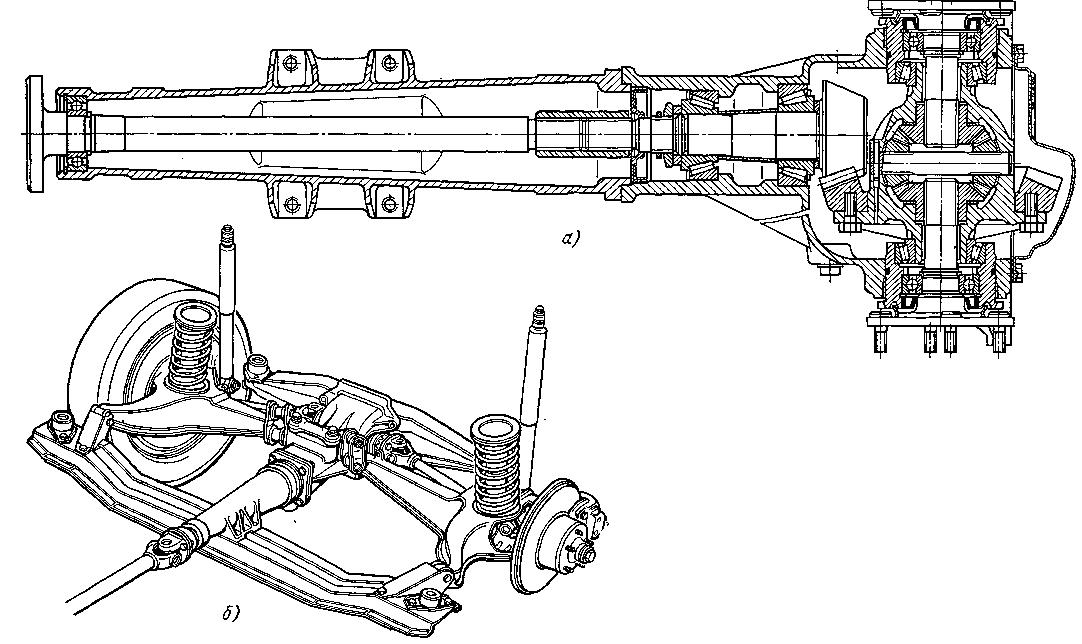
Fig. 6.28. Puntea de antrenare spate a automobilelor „Ford Zephyr” și „Zodiac IV”:
a - angrenaj principal și diferențial; b - vedere generală a podului suspendat

Fig. 6.29. Echipament principal și diferențial de alunecare limitată a unei mașini sport "Jaguar X"

Fig. 6.30. Puntea spate a mașinii Rover-2000
În plus, utilizarea unei extensii extrem de alungite a redus lungimea arborelui de antrenare și a eliminat rulmentul intermediar. Deoarece arbori de osie nu au o conexiune spline, sarcinile orizontale în timpul virajelor sunt transferate direct la angrenajul principal. Pentru a facilita fixarea axială a unității, se utilizează o tijă transversală sub forma unei conducte cu un diametru exterior de 22,2 mm, ale cărei capete sunt echipate cu bucșe de cauciuc cu o deformare limitată. Distanța nominală dintre axele acestor bucși este de 390 mm. Un capăt al tijei este înșurubat la baza corpului, iar celălalt la două proeminențe sudate pe suprafața din spate a suportului ștanțat montat pe carcasa angrenajului principal.
Tractoarele cultivatoare universale MTZ (Belarus) din clase de tracțiune medie (MTZ-80/82, 900th, 1000th, 1200th și 1500th) au practic un concept comun și același design al sistemului. Aceasta se aplică integral transmisiei - despre structura ei și părțile cele mai importante, citite în acest articol.
fenomen), cele mai utilizate cutii cu 9 angrenaje înainte și 2 trepte de mers (cu o viteză de reducere, numărul de viteze se dublează până la 18 înainte și 4 invers), de asemenea, cutii folosite cu 8 angrenaje înainte și 4 angrenaje roata din spate (cu un reductor 16 și respectiv 8). Cutia de viteze este amplasată în carterul său, care este fixat pe carcasa ambreiajului și face parte din cadrul de susținere al tractorului; Reducător de rampă - o cutie de viteze specială cu un raport de viteză de 7.104, care asigură deplasarea în față cu o viteză de 0,27-0,6 km / h (numai la 1 și 2 trepte de viteză) și înapoi la o viteză de 0,6-1,3 km / h . Unitatea este amplasată în carterul său, care este montat pe cutia de viteze din partea stângă; Axa spate - formată din angrenajele conice ale angrenajului principal, diferențial (corpul său are o conexiune cu șuruburi la angrenajul condus al GP) și două acțiuni finale. Toate piesele sunt amplasate în carterul său, conectate la carcasa cutiei de viteze șiTractoare MTZ cu motoare și accesorii Lombardini
Uzina de tractoare Minsk oferă câțiva ani noi modele de tractoare cu unități de alimentare Lombardini. Compania noastră, fiind un dealer MTZ, livrează aceste tractoare, precum și toate accesoriile la acestea și piese de schimb. Citiți despre tractoarele noi MTZ cu Lombardini și accesorii pentru acestea, caracteristicile și avantajele acestui echipament, citiți în acest articol.
rafinăria este una dintre puținele întreprinderi din țările CSI care nu numai că continuă să funcționeze, în ciuda anilor dificili din istoria țărilor noastre, dar creează constant echipamente noi, oferind consumatorilor dezvoltări moderne și relevante. Cu toate acestea, MTZ nu este o singură întreprindere situată în Minsk, ci o asociație de zece fabrici din Belarus care oferă un ciclu complet de producție de tractoare, echipamente speciale bazate pe acestea și diverse echipamente. Una dintre întreprinderile asociației MTZ - Fabrica de piese și unități de tractoare Bobruisk OJSC (BZTDiA), pe lângă piese de schimb, produce o linie întreagă a celor mai noi tractoare din clasa de tracțiune mică (0,6), principala caracteristică fiind unitățile de alimentare folosite ale companiei italiene Lombardini. Utilizarea motoarelor diesel italiene cu putere redusă (de la 36 la 60 CP) a făcut posibilă lansarea rapidă a tractoarelor universale de dimensiuni mici, cu o tracțiune bună și caracteristici operaționaleTractoare agricole din Rusia
Întrucât tractoarele au fost și rămân principalele echipamente utilizate în cultivarea câmpului, mulți producători ruși în ultimii ani au încercat să introducă soluții tehnice originale. Scopul constructorilor noștri de mașini agricole nu este atât de ambițios - cel puțin să țină în mână o parte a pieței interne, care este cucerită rapid de produsele importate.
5, care este, de fapt, o actualizare a celebrului Kirovets. Adevărat, creatorii noului model au abordat într-adevăr creativ dezvoltarea unui tractor cu un design clasic, echipându-l cu un post de control invers, care permite șoferului să conducă înapoi după ce a întors scaunul cu o coloană de direcție de 180 °, fără a compromite vizibilitatea și niciun disconfort personal. Tractoare Caterpillar În ciuda presiunii la sol mai mici și a tracțiunii mai mari, vânzările de tractoare omide în Rusia sunt neglijabile în comparație cu vânzările pe roți. Acest segment de piață a înghețat: nu se prăbușește „până la zero”, dar nici nu crește. Oricum ar fi, uzina de tractoare Volga a fost și rămâne liderul intern în producția acestor tipuri de mașini, care au produs la un moment dat cunoscutele modele de bază DT-75, VT-100. Acesta din urmă s-a extins ulterior într-o linie întreagă datorită VT-150 și VT-180 mai puternice, cu o suspensie combinată individual de role, careTractoarele din Belarus: tradiții bogate, înaintând
Astăzi, aproximativ 8% din tractoarele cu roți din lume se află în Republica Belarus, o țară cu o lungă tradiție în domeniul ingineriei. Gama de echipamente oferite de Belarusii este foarte bogată, iar prețul este plăcut în comparație cu omologii străini. Desigur, tractoarele MTZ și Polesye diferă doar ușor în ceea ce privește confortul față de cele importate.
da, dar în Rusia cu Ucraina. „Punctele slabe” ale tractoarelor din Belarus În general, toți consumatorii de mașini agricole din Belarusă observă concluziile de proiectare reușite care oferă funcționalitate ridicată a echipamentului în combinație cu o resursă de lucru mare. Și ideea de aici nu se rezumă doar la orele motorului, ci și la faptul că tractoarele MTZ și Polesye sunt capabile să funcționeze, așa cum spun ei, „sub presiune”, adică în pofida sarcinilor enorme pe șasiu și motor. Unitatea de alimentare care de cele mai multe ori eșuează astfel de mașini: sunt posibile probleme cu duze, supape, grupul manșonului pistonului, blocarea perechii cu piston, unghiul incorect de alimentare, etc. De asemenea, operatorii de mașini se plâng uneori de scurgeri de ulei, scurgeri de aer și alte defecte. Cu toate acestea, aceste „slăbiciuni” sunt rezultatul doar inexactităților din ansamblul de unități, care sunt eliminate fie independent, fie în centrele de servicii (din fericire, există multe din Federația Rusă). Menținerea atât a tractoarelor Minsk, cât și a Gomel