Mosfunksionimi kryesor i kondensatorit në sistemin e ndezjes së kontaktit është "prishja" e tij në "tokë". Në këtë rast, motori i makinës mund të jetë fare, ose papritmas. Shenjat tipike të jashtme të një mosfunksionimi janë: shkëndija e fortë midis kontakteve të ndërprerësit gjatë ndezjes së motorit dhe një shkëndijë shumë e dobët ose mungesa e plotë e saj.
Ka disa mënyra për të kontrolluar kondensatorin në makinat VAZ 2105, 2107.
- Me anë të një llambë kontrolli.
Ne shkëputim telin që vjen nga spiralja e ndezjes dhe telin e kondensatorit nga shpërndarësi (ato janë bashkangjitur në një terminal "K" të ndërprerësit). Midis tyre ne lidhim një llambë kontrolli, ndezim ndezjen dhe e vëzhgojmë atë. Ka marrë zjarr - kondensatori është "i prishur" dhe duhet të zëvendësohet. Jo - e saktë.
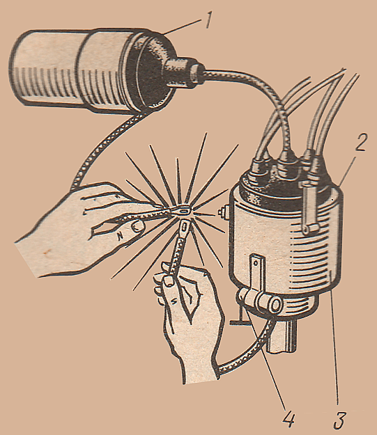
 1 - spiralja e ndezjes, 2 - mbulesa e shpërndarësit, 3 - shpërndarës, 4 - kondensator.
 - Me ndihmën e një teli nga bobina e ndezjes.
Ashtu si në metodën e përshkruar më sipër, ne shkëputim telin nga spiralja dhe telin e kondensatorit nga dalja në shpërndarës. Ne ndezim ndezjen. Ne prekim majat e telave. Kishte një shkëndijë - kondensatori është i gabuar. Jo, gjithçka është në rregull.
 1 - spiralja e ndezjes, 2 - mbulesa e shpërndarësit, 3 - shpërndarës, 4 - kondensator.
 - Duke karikuar me një rrymë të tensionit të lartë dhe më pas shkarkimin në tokë.
Ne e kthejmë boshtin me gunga në mënyrë që kontaktet e ndërprerësit në shpërndarës të jenë të mbyllura. Ne shkëputim vetëm telin e kondensatorit nga shpërndarësi. Ne ndezim ndezjen. Ne e sjellim majën e telit qendror të tensionit të lartë nga spiralja e ndezjes në majën e telit të kondensatorit. Ne i hapim kontaktet e ndërprerësit me një kaçavidë (ose mund ta ktheni shpërndarësin pak me dorë në mënyrë që kontaktet të shpërndahen). Një shkëndijë do të kërcejë midis majës së telit të tensionit të lartë dhe majës së telit të kondensatorit - kondensatori do të ngarkohet me një rrymë të tensionit të lartë. Ne e sjellim majën e telit të kondensatorit në trupin e tij. Shfaqja e një shkëndije shkarkimi me një klikim tregon gjendjen normale të kondensatorit. Nuk ka shkëndijë - kondensatori është i gabuar.
Shënime dhe shtesa
- Kondensatori në automjetet VAZ 2105, 2107 dhe modifikimet e tyre me një sistem ndezës kontakti është instaluar në shpërndarësin (30.3706-01) paralelisht me kontaktet e ndërprerësit dhe shërben për të rritur tensionin dytësor dhe për të parandaluar djegien e kontakteve. Karikohet kur kontaktet hapen dhe shkarkohen përmes mbështjelljes dytësore të spirales së ndezjes, gjë që shkakton një rritje të tensionit sekondar.
- Parametrat e funksionimit të kondensatorit të makinave VAZ 2105, 2107: kapaciteti i kondensatorit matet në intervalin e frekuencës 50 - 1000 Hz dhe është në intervalin 0,20-0,25 μF, rezistenca e izolimit në një temperaturë prej (100 ± 2) ºС dhe një tension DC prej 100 V duhet të jetë më shumë se 1 MΩ / uF.
Një makinë moderne është e vështirë të imagjinohet pa ndezje. Përparësitë kryesore që ofron sistemi elektronik i ndezjes janë të njohura, ato janë si më poshtë:
djegia më e plotë e karburantit dhe rritja e lidhur me fuqinë dhe efikasitetin;
reduktimi i toksicitetit të gazrave të shkarkimit;
lehtësim për fillimin e ftohtë
rritja e burimit të kandelave;
konsumi i reduktuar i energjisë;
mundësia e kontrollit me mikroprocesor të ndezjes.
Por e gjithë kjo kryesisht vlen për sistemin CDI.
Për momentin, në industrinë e automobilave praktikisht nuk ka sisteme ndezëse të bazuara në akumulimin e energjisë në një kondensator: CDI (Ndezja e shkarkimit të kondensatorit) - është gjithashtu tiristor (kondensator) (përveç motorëve të importuar me 2 goditje). Dhe sistemet e ndezjes bazuar në akumulimin e energjisë në induktivitet: ICI (induktor i mbështjelljes së ndezjes) i mbijetoi momentit të kalimit nga kontaktet në çelsat, ku kontaktet e ndërprerësit u zëvendësuan rëndom nga një çelës tranzistor dhe një sensor Hall pa pësuar ndryshime thelbësore (një shembull e ndezjes në VAZ 2101 ... 07 dhe në sistemet integrale të ndezjes VAZ 2108 ... 2115 dhe më gjerë). Arsyeja kryesore për shpërndarjen dominuese të sistemeve të ndezjes ICI është mundësia e ekzekutimit integral, i cili kërkon prodhim më të lirë, thjeshtim të montimit dhe instalimit, për të cilin përdoruesi fundor paguan.
Me këtë, si të thuash, sistemi ICI ka të gjitha disavantazhet, kryesore prej të cilave është shkalla relativisht e ulët e magnetizimit të bërthamës dhe, si rezultat, një rritje e mprehtë e rrymës së dredha-dredha parësore me rritjen e shpejtësisë së motorit dhe energjisë humbje. Kjo çon në faktin se me një rritje të shpejtësisë, ndezja e përzierjes përkeqësohet, si rezultat, faza e momentit fillestar të rritjes së presionit të ndezjes humbet dhe efikasiteti përkeqësohet.
Një zgjidhje e pjesshme, por larg nga më e mira, për këtë problem është përdorimi i mbështjellësve me ndezje të dyfishtë dhe katërkëndësh (të ashtuquajturat). Me këtë, prodhuesi shpërndau ngarkesën në frekuencën e rimagnetizimit nga një spirale ndezëse në dy ose katër. duke reduktuar frekuencën e rimagnetizimit të bërthamës për ndezjen e një spiraleje.
Dua të vërej se në makinat me një qark ndezës (VAZ 2101 ... 2107), ku shkëndija formohet duke ndërprerë rrymën në një spirale mjaftueshëm me rezistencë të lartë me një ndërprerës mekanik, që e zëvendëson atë me një çelës elektronik nga ose e ngjashme në makinat me një spirale me rezistencë të lartë nuk bën gjë tjetër veçse zvogëlon ngarkesën aktuale për kontakt.
Fakti është se parametrat RL të spirales duhet të plotësojnë kërkesat kontradiktore. Së pari, rezistenca aktive R duhet të kufizojë rrymën në një nivel të mjaftueshëm për të grumbulluar sasinë e kërkuar të energjisë gjatë fillimit, kur tensioni i baterisë mund të bjerë me 1.5 herë. Nga ana tjetër, rryma e tepërt çon në dështim të parakohshëm të grupit të kontaktit, prandaj kufizohet nga variatori ose kohëzgjatja e pulsit të pompës c. Së dyti, për të rritur sasinë e energjisë së ruajtur, është e nevojshme të rritet induktiviteti i spirales. Në të njëjtën kohë, me një rritje të revolucioneve, thelbi nuk ka kohë për të rimagnetizuar (siç përshkruhet më lart). Si rezultat, voltazhi sekondar në spirale nuk ka kohë për të arritur vlerën nominale, dhe energjia e shkëndijës, proporcionale me katrorin e rrymës, zvogëlohet ndjeshëm me shpejtësi të lartë (më shumë se ~ 3000) motor.
Përparësitë e një sistemi të ndezjes elektronike manifestohen më plotësisht në një sistem ndezës kondensator me ruajtje të energjisë në një rezervuar, dhe jo në një bërthamë. Një nga opsionet për sistemin e ndezjes së kondensatorit përshkruhet në këtë artikull. Pajisjet e tilla plotësojnë shumicën e kërkesave për sistemin e ndezjes. Sidoqoftë, shpërndarja e tyre në masë pengohet nga prania në qarkun e një transformatori pulsi të tensionit të lartë, prodhimi i të cilit është një vështirësi e njohur (më shumë për këtë më poshtë).
Në këtë qark, kondensatori i tensionit të lartë ngarkohet nga një konvertues DC / DC, në transistorët P210, kur merret një sinjal kontrolli, tiristori lidh kondensatorin e ngarkuar me mbështjelljen kryesore të spirales së ndezjes, ndërsa DC-DC funksionon në modalitetin e gjeneratorit bllokues ndalon. Spiralja e ndezjes përdoret vetëm si transformator (qarku LC me ndikim).
Në mënyrë tipike, voltazhi në mbështjelljen parësore normalizohet në 450 ... 500 V. Prania e një gjeneratori me frekuencë të lartë dhe stabilizimi i tensionit e bën sasinë e energjisë së ruajtur praktikisht të pavarur nga tensioni i baterisë dhe shpejtësia e boshtit. Një strukturë e tillë është shumë më ekonomike sesa kur energjia ruhet në një induktor, pasi rryma rrjedh nëpër spiralen e ndezjes vetëm në momentin e ndezjes. Përdorimi i një konverteri vetëlëkundës me 2 goditje bëri të mundur ngritjen e efikasitetit në 0.85. Skema e mëposhtme ka avantazhet dhe disavantazhet e saj. TE virtytet duhet t'i atribuohet:
normalizimi i tensionit dytësor, pavarësisht nga shpejtësia e boshtit të gungës në intervalin e shpejtësisë së funksionimit.
thjeshtësia e dizajnit dhe, si rezultat, besueshmëria e lartë;
efikasitet të lartë.
Për disavantazhet:
ngrohje e fortë dhe, si rezultat, është e padëshirueshme ta vendosni në vendin e ndarjes së motorit. Vendndodhja më e mirë, për mendimin tim, është parakolpi i makinës.
Krahasuar me sistemin e ndezjes ICI me ruajtjen e energjisë në spiralen e ndezjes, ndezja e kondensatorit (CDI) ka përparësitë e mëposhtme:
shkallë e lartë e goditjes së tensionit të lartë;
dhe kohë e mjaftueshme e djegies së harkut (0,8 ms) dhe, si rezultat, një rritje në presionin e ndezjes së përzierjes së karburantit në cilindër, për shkak të kësaj, rritet rezistenca e motorit ndaj shpërthimit;
energjia e qarkut sekondar është më e lartë, sepse normalizohet nga koha e djegies së harkut nga momenti i ndezjes (MZ) deri në qendrën e sipërme të vdekur (TDC) dhe nuk kufizohet nga bërthama e spirales. Si rezultat - ndezshmëri më e mirë e karburantit;
djegie më e plotë e karburantit;
vetë-pastrim më i mirë i kandelave, dhomave të djegies;
mungesa e ndezjes paraprake.
konsumimi më pak gërryes i kontakteve të kandelave, distributori. Si rezultat - një jetë më e gjatë shërbimi;
nisje e sigurt në çdo mot, edhe në një bateri të ngordhur. Njësia fillon të funksionojë me siguri nga 7 V;
funksionimi i butë i motorit, për shkak të vetëm një pjese me djegie.
Për transformatorin, përdoret një unazë me përshkueshmëri magnetike h = 2000, një seksion >= 1,5 cm 2 (për shembull, u treguan rezultate të mira: "bërthama M2000NM1-36 45x28x12").
Të dhënat e mbështjelljes:
Teknologjia e montimit:
Dredha-dredha aplikohet me kthesë për të kthyer një copë litari epokside të sapombarsur.
Pas përfundimit të shtresës ose mbështjelljes në një shtresë - mbështjellja mbulohet me rrëshirë epokside derisa të mbushen boshllëqet e ndërrimit.
Dredha-dredha mbyllet me një copë litari mbi rrëshirë epoksi të freskët, duke shtrydhur tepricën. (për shkak të mungesës së impregnimit me vakum)
Ju gjithashtu duhet t'i kushtoni vëmendje përfundimit të përfundimeve:
vihet një tub fluoroplastik dhe fiksohet me një fije najloni. Në mbështjelljen e ngritjes, telat janë fleksibël, të bërë me tel: MGTF-0.2 ... 0.35.
Pas impregnimit dhe izolimit të rreshtit të parë (mbështjellja 1-2-3, 4-5-6), një dredha-dredha në rritje (7-8) është mbështjellë rreth të gjithë unazës në shtresa, kthejeni për t'u kthyer. , ekspozimi i shtresave, "qengjat" - nuk lejohen.
Nga cilësia e prodhimit të transformatorit, besueshmëria dhe qëndrueshmëria e njësisë janë pothuajse zili.
Vendndodhja e mbështjelljes është treguar në figurën 3.

Për shpërndarje më të mirë të nxehtësisë, rekomandohet montimi i bllokut në një kuti me fije duralumini, madhësia e përafërt është 120 x 100 x 60 mm, trashësia e materialit është 4...5 mm.
Transistorët P210 vendosen në murin e kasës përmes një copë litari izolues që përcjell nxehtësi.
Montimi kryhet me montim të varur, duke marrë parasysh rregullat për montimin e pajisjeve me tension të lartë, impuls.
Pllaka e kontrollit mund të bëhet në një tabelë qark të printuar ose në një tabelë prototipi.
Pajisja e përfunduar nuk kërkon rregullim, është e nevojshme vetëm të sqarohet përfshirja e mbështjelljes 1, 3 në qarkun e tranzitorit bazë, dhe nëse gjeneratori nuk fillon, ndërroni ato.
Kondensatori i instaluar në shpërndarës kur përdoret CDI është i fikur.
Detajet
Praktika ka treguar se një përpjekje për të zëvendësuar transistorët P210 me ato moderne silikoni çon në një ndërlikim të konsiderueshëm të qarkut elektrik (shih 2 diagramet më të ulëta në KT819 dhe TL494), nevojën për akordim të kujdesshëm, i cili pas një deri në dy vjet funksionimi në gjendje të rëndë kushtet (ngrohje, dridhje) duhet të kryhen përsëri.
Praktika personale që nga viti 1968 ka treguar se përdorimi i tranzistorëve P210 ju lejon të harroni njësinë elektronike për 5 ... 10 vjet, dhe përdorimin e komponentëve me cilësi të lartë (veçanërisht një kondensator ruajtjeje (MBGCH) me një dielektrik të gjatë pa moshë) dhe prodhimi i saktë i një transformatori - dhe për një periudhë më të gjatë .
1969-2006 Të gjitha të drejtat për këtë dizajn qarku i përkasin VV Alekseev. Kur riprintoni kërkohet një lidhje.
Ju mund të bëni një pyetje në adresën e treguar në këndin e poshtëm djathtas.
Letërsia
A. Kurchenko, A. Sinelnikov
Sistemi i propozuar i ndezjes ndryshon nga ai i përshkruar në koleksionin "Për të ndihmuar Radio Amatorin", nr. 73 (M.: DOSAAF, 1981) nga fakti se kondensatori i ruajtjes në të është i ngarkuar vazhdimisht, dhe për këtë arsye rrjedhjet në elementët e qarkut sekondar nuk ndikojnë në funksionimin e sistemit.
Sistemi është rezistent ndaj zhurmës; funksionon normalisht në prani të zhurmës së impulsit me një amplitudë deri në 80 V në rrjetin në bord.
Modaliteti i ndezjes së shumëfishtë nuk ofrohet. Kalimi nga një sistem elektronik në një sistem baterie konvencionale bëhet duke përdorur lidhëset e prizës.
Sistemi siguron një tension sekondar të stabilizuar prej 360 ± 10 V kur tensioni i furnizimit ndryshon nga 6.5 në 15 V, si dhe kur temperatura ndryshon nga -40 në +70 °C.
Rryma e konsumuar nga sistemi ndryshon në mënyrë lineare nga 0.4 A me motorin e ndaluar në 1.8 A me një shpejtësi motori me katër cilindra me katër goditje prej 6000 rpm.
Kohëzgjatja e shkarkimit të shkëndijës është 0,3 μs, dhe energjia e saj nuk është më pak se 5,9 mJ.
Skema e qarkut elektrik të pajisjes ndezëse të konsideruar është paraqitur në fig. 1.

Sistemi i ndezjes përbëhet nga një ndërprerës Pr, një njësi elektronike e njësisë elektronike, një pajisje për kalimin nga ndezja elektronike në ndezjen e baterisë, e përbërë nga lidhësit e prizës XP1, XS1, XP2, një spirale ndezëse me qark të shkurtër, një ndërprerës ndezës VZ, një bateria GB, një çelës motori Vst.
Njësia elektronike e EB, nga ana tjetër, përbëhet nga përbërësit kryesorë të mëposhtëm:
konverteri i tensionit me një cikël në transistorin VT2 dhe transformatorin T1;
pajisje stabilizimi, e përbërë nga një diodë zener VD9 dhe një përforcues DC bazuar në transistorët VT1 VT3, VT4, VT5;
kondensator ruajtës C3
një pajisje komutuese e përbërë nga një tiristor VS1, një transformator kontrolli T2, rezistorë R5, R6, një kondensator C2 dhe një diodë VD8;
dioda e shkarkimit VD7.
Pajisja funksionon si më poshtë. Le të supozojmë se kontaktet e ndërprerësit Pr janë të hapura në momentin e ndezjes. Pas ndezjes së energjisë, konverteri i tensionit fillon të funksionojë. Nuk ka tension në kondensatorin e ruajtjes C3 në këtë kohë, kështu që dioda zener VD9 dhe transistori VT3 janë të mbyllura. Transistorët VT4, VT5 janë të hapur. E para prej tyre është rryma në bazën e saj përmes rezistorit R11, dhe e dyta është rryma e kolektorit të tranzitorit VT4 në bazën e tij përmes rezistencës R14. Transistori i hapur VT5 largon kryqëzimin bazë-emetues të tranzitorit VT1, si rezultat i të cilit ky i fundit mbyllet dhe nuk ndikon në funksionimin e konvertuesit. Transistori VT2 i konvertuesit hapet fillimisht nga rryma në bazën e tij përmes rezistorit R1. Në këtë rast, tensioni i plotë i furnizimit zbatohet në mbështjelljen 1 të transformatorit T1. Tensionet induktohen në mbështjelljet e mbetura të transformatorit. Tensioni negativ nga fillimi i mbështjelljes II (fillimi i mbështjelljes në diagramin në Fig. 1 tregohet me pika) përmes diodës VD5 dhe rezistorit R2 hyn në bazën e tranzitorit VT2 dhe e vendos tranzitorin VT2 në ngopje. Përmes mbështjelljes I të transformatorit T1, fillon të rrjedhë një rrymë në rritje lineare (t1 në Fig. 2).

Të cilën do ta quajmë rrymë thyerjeje, tranzistori VT2 fillon të bllokohet. Tensioni në të rritet, dhe në mbështjelljen I zvogëlohet. Si rezultat, voltazhi në mbështjelljen II gjithashtu zvogëlohet, gjë që përshpejton procesin e fikjes së transistorit VT2, i cili fiket brenda disa mikrosekondave. Tensioni në mbështjelljet e transformatorit T1 ndryshon shenjën e tij. Një tension pozitiv nga fillimi i mbështjelljes II përmes rezistorit R4 aplikohet në bazën e tranzistorit VT2 dhe e mbyll atë në mënyrë të sigurt. Rryma përmes tranzistorit VT2 dhe mbështjelljes I të transformatorit T1 ndalon (t2 në Fig. 2). Kjo përfundon drejtimin përpara të konvertuesit. Një tension i kundërt aplikohet në diodën VD6 gjatë goditjes përpara nga mbështjellja III, prandaj dioda mbyllet dhe qarku sekondar (elementet e vendosur në diagramin në Fig. 1 në të djathtë të diodës VD6) nuk ndikon në funksionimin e konverteri.
Oriz. Fig. 2. Diagramet e kohës së funksionimit të një konverteri të tensionit të stabilizuar me një cikël: UIII, Uc3 - tension, përkatësisht, në mbështjelljen III dhe kondensatorin C3, i1, - rryma përmes mbështjelljes I të transformatorit T1

Pas një ndërprerjeje të rrymës në mbështjelljen I të transformatorit T1, fillon funksionimi i kundërt i konvertuesit.
Energjia e grumbulluar në fushën magnetike të transformatorit krijon impulse tensioni me polaritet të kundërt në mbështjelljet e tij. Një impuls pozitiv nga fillimi i mbështjelljes III hap diodën VD6 dhe ngarkon kondensatorin e ruajtjes në një tension që varet nga energjia e akumuluar në fushën magnetike të transformatorit gjatë lëvizjes përpara dhe kapaciteti i kondensatorit të ruajtjes (t3 në Fig. . 2).
Nëse supozojmë se e gjithë energjia e akumuluar në fushën magnetike të transformatorit T1 gjatë lëvizjes përpara shndërrohet në energjinë e fushës elektrike të kondensatorit, atëherë voltazhi në të cilin do të ngarkohet kondensatori i ruajtjes do të jetë:

Ku ip është forca e rrymës së thyerjes; L1 - induktiviteti i mbështjelljes I.
Kohëzgjatja e pulsit të kundërt varet gjithashtu nga energjia e ruajtur në transformator dhe kapaciteti i kondensatorit të ruajtjes C3 dhe, përveç kësaj, siç mund të shihet nga Fig. 2, zvogëlohet me rritjen e amplitudës së pulsit. Në të vërtetë, energjia e secilit puls është konstante - L1 (ip) katror / 2, prandaj, zona e pulsit është konstante, ndërsa lartësia e pulsit rritet gjatë gjithë kohës dhe, për rrjedhojë, kohëzgjatja e tij duhet të ulet.
Pas përfundimit të pulsit të kundërt (t4 në figurën 2), voltazhi pozitiv në mbështjelljet e transformatorit T1 zhduket, transistori VT2 hapet përsëri dhe proceset e mësipërme përsëriten.
Tensioni në kondensatorin e ruajtjes rritet me hapa. Kur arrin vlerën e caktuar prej 350 ... 360 V (t5 në Fig. 2), e cila përcaktohet nga rezistenca e rezistorëve R7, R8, R9 dhe tensioni i stabilizimit të diodës zener VD9, kjo e fundit hapet. Transistorët VT3, VT1 hapen dhe transistorët VT4, VT5 mbyllen. Reagimet pozitive përmes rezistencës R12 përshpejtojnë procesin e ndërrimit të transistorëve VT1, VT3, VT4, VT5 të amplifikatorit të stafetës dhe, përveç kësaj, rrit stabilitetin e tij. Kondensatori C4 gjithashtu rrit stabilitetin e amplifikatorit.
Kalimi kolektor-emetues i tranzistorit të hapur VT1 përmes diodës VD1 shmang kalimin e emetuesit-bazë të tranzitorit VT2, si rezultat i të cilit ky i fundit mbyllet dhe konverteri ndalon së punuari. Kondensatori i ruajtjes shkarkohet ngadalë përmes rezistorëve R7, R8, R9, diodës zener VD9 dhe rezistencës ndaj rrjedhjes së tiristorit VS1, diodave VD6, VD7 dhe rezistencës së tij të izolimit. Pas ca kohësh, voltazhi në kondensatorin e ruajtjes zvogëlohet aq shumë sa mbyllet dioda zener VD9. Transistorët VT3 dhe VT1 të amplifikatorit rele mbyllen, dhe transistorët VT4, VT5 hapen. Konvertuesi fillon të punojë përsëri (t6 në Fig. 2). Impulsi i parë i kundërt rimbush kondensatorin e ruajtjes, voltazhi në të rritet dhe dioda zener VD9 dhe transistorët VT3 dhe VT1 hapen përsëri. Konvertuesi ndalon së punuari përsëri, etj.
Kështu, niveli mesatar i tensionit në kondensatorin e ruajtjes mbahet konstant. Me një ulje të tensionit të furnizimit, rryma e thyerjes zvogëlohet - ip, dhe, rrjedhimisht, energjia e grumbulluar në fushën magnetike të transformatorit gjatë drejtimit përpara. Sidoqoftë, në të njëjtën kohë, frekuenca e funksionimit të konvertuesit rritet dhe kondensatori i ruajtjes fillon të rimbushet më shpesh. Si rezultat, niveli mesatar i tensionit në të mbetet konstant. Kështu, për shembull, testet kanë treguar se me një rritje të tensionit të furnizimit nga 6.5 në 15 V, d.m.th. me 230%, voltazhi në kondensatorin e ruajtjes rritet me vetëm 2%, nga 360 në 367 V.
E njëjta gjë ndodh kur rritet rryma e rrjedhjes në qarkun sekondar. Kondensatori i ruajtjes fillon të shkarkohet më shpejt, por gjithashtu rikarikohet më shpesh. Si rezultat, niveli mesatar i tensionit në të mbetet konstant.
Amplituda e valëzimeve, ose madhësia e hapit të tensionit në kondensatorin e ruajtjes, në gjendje të qëndrueshme varet nga energjia e ruajtur në fushën magnetike të transformatorit gjatë lëvizjes përpara. Sa më e vogël të jetë kjo energji, aq më e vogël është madhësia e hapit. Në praktikë, madhësia e hapit nuk duhet të kalojë 10 ... 15 V. Përndryshe, voltazhi i ndezjes rezulton të jetë praktikisht i pastabilizuar. Në të vërtetë, duke qenë se funksionimi i konvertuesit nuk stabilizohet me funksionimin e ndërprerësit, kontaktet e këtij të fundit mund të hapen në çdo kohë. Nga fig. 2 mund të shihet se voltazhi i aplikuar në bobinën e ndezjes do të jetë më i madh nëse ndërprerësi hapet në t5 në vend të t7. Nëse amplituda e hapit, për shembull, është 70 V, atëherë voltazhi i ndezjes nuk mund të konsiderohet i stabilizuar.
Kërkesa e dytë, dhe në të njëjtën kohë shumë e rëndësishme për konvertuesin, nëse është projektuar për të punuar në sistemin e ndezjes, është shpejtësia e tij. Ai duhet të ketë kohë për të ngarkuar kondensatorin e ruajtjes në kohën midis dy shkëndijave, në një frekuencë maksimale të ndezjes prej 200 Hz, d.m.th., në 5 ms.
Shpejtësia e konvertuesit përcaktohet kryesisht nga ip-ja e rrymës së ndërprerjes. Sa më i madh të jetë, aq më i madh është çdo pjesë e energjisë dhe aq më shpejt ngarkohet kondensatori i ruajtjes. Megjithatë, në këtë rast rritet edhe koha e ngritjes së rrymës. Sidoqoftë, kjo e fundit rritet në raport me fuqinë e parë të rrymës, dhe energjia në proporcion me katrorin e rrymës. Prandaj, koha totale e karikimit të kondensatorit të ruajtjes zvogëlohet me një rritje të rrymës së thyerjes. Shpejtësia e konvertuesit praktikisht nuk varet nga induktiviteti i mbështjelljes parësore I të transformatorit. Sa më i madh të jetë induktiviteti, aq më i madh është çdo pjesë e energjisë, por rryma rritet po aq ngadalë. Koha e funksionimit përpara është rritur. Me një rritje të induktivitetit të mbështjelljes I, për shembull, duke rritur seksionin kryq të bërthamës së transformatorit, frekuenca e konvertuesit zvogëlohet, kondensatori ngarkohet plotësisht, për shembull, në 3-4 impulse të kundërt, megjithatë, Koha totale e karikimit është e njëjtë si me një induktivitet më të ulët, kur kondensatori ngarkohet në 10-15 impulse. Në të njëjtën kohë, madhësia e hapit në gjendjen e qëndrueshme në rastin e parë është më e madhe dhe, përveç kësaj, transformatori ka dimensione dhe peshë të madhe.
Prandaj, dizajni i transformatorit të konvertuesit mund të jetë shumë i ndryshëm. Është e nevojshme vetëm që humbjet në bakër (në dredha-dredha I) të jenë afërsisht të barabarta me humbjet në çelik (në bërthamë), të cilat mund të përcaktohen nga shkalla e ngrohjes së mbështjelljes dhe bërthamës (ato duhet të nxehen afërsisht njësoj ). Për më tepër, frekuenca e konvertuesit në modalitetin kalimtar (t1 - t5 në Fig. 2) nuk duhet të kalojë 10 ... 15 kHz, pasi me rritjen e frekuencës, humbjet në tranzitorin VT2 dhe bërthamën e transformatorit rriten.
Me një ulje të tensionit të furnizimit, rryma e ndërprerjes zvogëlohet dhe, rrjedhimisht, rritet koha totale e karikimit të kondensatorit të ruajtjes. Sidoqoftë, frekuenca e ndezjes është gjithashtu e ulët, për shembull, kur filloni motorin me një startues, dhe kondensatori i ruajtjes ka ende kohë për t'u ngarkuar plotësisht.
Le të ndalemi në qëllimin e disa elementeve të konvertuesit.
Dioda VD1 mbron transistorin VT1 nga voltazhi i polaritetit pozitiv që shfaqet në mbështjelljen II (bazuar në tranzitorin VT2) gjatë goditjes së kundërt.
Dioda VD4 kompenson rënien e tensionit në të gjithë diodën VD1, e cila është e nevojshme për mbylljen e besueshme të transistorit VT2 kur transistori VT1 është i zhbllokuar.
Falë diodës VD5, e lidhur paralelisht me rezistencën R4, gjysmëvala negative e tensionit nga mbështjellja II kalon në bazën e tranzistorit VT2 përmes kësaj diode pothuajse plotësisht, dhe gjysmëvala pozitive është e kufizuar në një nivel të pranueshëm. niveli për tranzistorin VT2 nga diodat VD2, VD3.
Kur kontaktet e ndërprerësit janë të mbyllura, rryma fillon të rrjedhë përmes rezistorëve R5, R6 dhe diodës VD8. Tensioni në mbështjelljen I të transformatorit T2 është i kufizuar nga dioda VD8, dhe për këtë arsye amplituda e pulsit negativ në elektrodën e kontrollit të tiristorit VS1 në momentin e mbylljes së kontakteve të ndërprerësit nuk kalon 0,35 V. Kufizimi i tensionit në mbështjelljen I, përveç kësaj, siguron një rritje të kohës së ngritjes aktuale.
Rezistorët R5, R6 kufizojnë rrymën përmes mbështjelljes I dhe së bashku me kondensatorin C2 formojnë një filtër me kalim të ulët që siguron imunitetin e nevojshëm ndaj zhurmës së sistemit të ndezjes.
Në kohën kur kontaktet e ndërprerësit hapen, rryma në mbështjelljen I arrin një vlerë të qëndrueshme. Energjia elektromagnetike grumbullohet në bërthamën e transformatorit T2. Prandaj, në momentin e hapjes së kontaktit, impulset e tensionit shfaqen në mbështjelljet e transformatorit. Një impuls pozitiv nga fundi i mbështjelljes II furnizohet në elektrodën e kontrollit të tiristorit VS1, si rezultat i të cilit ky i fundit kalon (t1 në Fig. 3).
Oriz. Fig. 3. Diagramet e kohës së funksionimit të sistemit të ndezjes me ruajtje të vazhdueshme të energjisë në momentin e konvertimit: Uc3 - tension në kondensatorin e ruajtjes C3, Ikz - rrymë përmes mbështjelljes parësore të bobinës së ndezjes, Ucv - tension në shkëndijë në prizë dredha-dredha, e cila eliminon efektin e kërcimit të kontaktit të ndërprerësit.

Dredha-dredha kryesore e spirales së ndezjes është e lidhur me një kondensator ruajtjeje C3 të ngarkuar në një tension prej 350 V dhe tensioni në të rritet në 350 V (Ukz) brenda disa mikrosekondave. Shkalla e rritjes së tensionit dytësor varet nga parametrat e spirales së ndezjes. Kur përdorni mbështjellje serike nga një sistem konvencional i ndezjes së baterisë (për shembull, B117), ndodh një shkëndijë 3 ... 5 μs pas hapjes së kontakteve të ndërprerësit (t2 në Fig. 3).
Induktiviteti i mbështjelljes primare të mbështjelljes së ndezjes dhe kondensatorit të ruajtjes C3, të ndërlidhur përmes një tiristori të ndërprerë, formojnë një qark oshilues në të cilin ndodhin lëkundje të amortizuara. Rryma në qarkun -Ikz, që rrjedh në këtë kohë përmes tiristorit dhe mbështjelljes parësore të spirales së ndezjes, siç mund të shihet nga Fig. 3 vonon tensionin me 90°. Pas një çerek të periudhës, në kohën t3, rryma në qark arrin një maksimum, dhe voltazhi në kondensator bëhet i barabartë me zero, dhe më pas ndryshon shenjën e tij dhe bëhet negativ. Sapo voltazhi në kondensatorin e ruajtjes bëhet negativ, dioda VD6 hapet dhe rryma Ivd6 fillon të rrjedhë përmes saj dhe mbështjelljes III të transformatorit T1, duke ngarkuar konvertuesin dhe duke e penguar atë të fillojë të punojë. Pas gjysmë cikli, në kohën t4, rryma në qark bëhet zero dhe tiristori fiket. Sidoqoftë, falë diodës VD7, qarku oscilues nuk shkatërrohet. Tensioni në kondensatorin e ruajtjes në këtë kohë (t4 në Fig. 3) është negativ, dioda VD7 hapet dhe rryma e qarkut tani rrjedh nëpër të.
Pas një gjysmë periudhe tjetër në kohën t5, rryma në qark përsëri zvogëlohet në zero, dioda VD7 mbyllet dhe qarku oscilues shkatërrohet. Dredha-dredha parësore I e mbështjelljes së ndezjes shkëputet nga kondensatori i ruajtjes dhe shkarkimi i shkëndijës në qiri ndalon. Megjithatë, dioda VD6 mbetet e hapur për rreth 150 μs derisa energjia e akumuluar në fushën magnetike të transformatorit T1 (për shkak të rrymës Ivd6 që rrjedh nëpër mbështjelljen III) të harxhohet për rimbushjen e kondensatorit të ruajtjes (t5 -t6 në Fig. 3 ). Siç shihet nga fig. 3, në momentin t5, kur dioda VD7 mbyllet dhe qarku oscilues është shkatërruar, ka një tension pozitiv U2 në kondensatorin e ruajtjes, i cili është afërsisht 30% e tensionit fillestar U1. Vlera e tensionit U2 përcaktohet nga energjia e lëshuar në shkarkimin e shkëndijës së kandelit, e cila mund të llogaritet me formulën

Energjia e çliruar në një shkarkim të shkëndijës, ceteris paribus, varet nga madhësia e hendekut të shkëndijës së kandelit. Me rritjen e madhësisë së hendekut të shkëndijës, tensioni U2 zvogëlohet dhe, rrjedhimisht, energjia e çliruar në shkarkimin e shkëndijës rritet.
Nga fig. 3 mund të shihet se kohëzgjatja e shkarkimit të shkëndijës në sistemin e përshkruar (kur punoni me spiralen B117) është afërsisht 0.3 ms. Për më tepër, shkarkimi i shkëndijës përbëhet nga dy pjesë - pozitive dhe negative, që korrespondojnë me gjysmë-valët pozitive dhe negative të rrymës në mbështjelljen parësore të spirales së ndezjes.
Kohëzgjatja relativisht e shkurtër e shkarkimit të shkëndijës nuk është një disavantazh i sistemit të përshkruar. Siç kanë treguar studimet, në një motor të shërbimit dhe të llogaritur saktë, pas arritjes së një regjimi termik normal, ndezja e përzierjes së punës ndodh brenda 10 ... elektrodave të kandelave, duke zvogëluar jetën e tyre të shërbimit. Një shkëndijë me një kohëzgjatje prej 1,0 ms ose më shumë mund të jetë e dobishme vetëm kur ndizni motorin në një përzierje të pasur, të nxehtë dhe të ftohtë.
Duhet të theksohet këtu se në sistemin e përshkruar të ndezjes me një konvertues me një cikël, kohëzgjatja e shkarkimit të shkëndijës nuk mund të rritet duke lidhur diodat paralelisht me mbështjelljen parësore të spirales së ndezjes, siç bëhet në sistemin me energji pulsuese. ruajtja e përshkruar në HSR nr. 73.
Kur diodat janë të lidhura, sistemi ndalon së punuari. Konsumi aktual rritet në 3 A, dhe shkëndija ndalon. Kjo është për shkak se voltazhi i kondensatorit të ruajtjes nuk shkon më negativ gjatë ndezjes. Konvertuesi vazhdon të punojë gjatë gjithë kohës dhe tiristori kyç nuk fiket. Konvertuesi kthehet në një gjenerator të rrymës që ushqen tiristorin.
Tensioni në kondensatorin e ruajtjes është atëherë i barabartë me rënien e tensionit në tiristorin e ndërprerë.
Në mënyrë që sistemi të mund të punojë me një diodë, ai duhet të pajiset me një pajisje shtesë, për shembull, një multivibrator i frenuar që bllokon transistorin VT2 të konvertuesit për kohëzgjatjen e shkarkimit të shkëndijës.
Ndërtimi dhe detajet. Dizajni i njësisë elektronike mund të jetë më arbitrar. Megjithatë, trupi i bllokut duhet të jetë prej aliazh alumini, i cili do të sigurojë shpërndarje të mirë të nxehtësisë për elementët e ngrohjes. Përveç kësaj, duhet të jetë i papërshkueshëm nga spërkatja, pasi nuk përjashtohet hyrja e ujit gjatë funksionimit.
Transistori VT2, diodat VD4 dhe VD7, tiristori VS1 duhet të instalohen në radiatorët ftohës. Elementet e mbetura janë të vendosura në tabelën e qarkut të printuar. Lidhësi XP1 është montuar në trupin e bllokut. Një parzmore telash me gjatësi dhe ngjyra të ndryshme del nga lidhësi XP1 për t'u lidhur me pikat përkatëse të qarkut në makinë. Lidhësi XP2 është i mbyllur me një prizë cilindrike në anën e montimit, dhe me një kapak me një zinxhir në anën e kunjave (në mënyrë që mbulesa të mos humbasë) dhe është e fiksuar në parzmoren e lidhjes së lidhësit XS1.
Lidhës XP1, XP2 të përdorura 2RM 18B 7Sh1V1, lidhës XS1 - 2RM. 18KPN 7G1V1.
Llojet e pajisjeve gjysmëpërçuese, vlerat dhe fuqitë e rezistorëve, si dhe vlerësimet e kondensatorëve janë paraqitur në diagramin në fig. 1. Rezistorët fiks janë të tipit MLT. Rezistenca e ndryshueshme R8-SP5-1a, SP5-2. Cilësia e kësaj rezistence, qëndrueshmëria e saj kohore varet nga qëndrueshmëria e përkohshme e tensionit dytësor të bllokut.
Kondensatorët C1, C4 mund të jenë të çdo lloji: mikë, film, qeramikë, letër metalike, etj., por gjithmonë jo elektrolitikë, për një tension prej të paktën 50 V, me çdo devijim të kapacitetit të lejuar nga nominali dhe nga çdo koeficient i temperaturës. të kapacitetit. Kondensatori C1, për shembull, mund të jetë MBM-160-0,05 ± 20%, dhe kondensatori C4 - BM-2-200V-0,01 ± 20%.
Kondensatori C3 - MBGCH, MBGO, MBGP për një tension më të vogël se 500 V. Mund të përdorni gjithashtu dy kondensatorë MBM prej 0,5 mikrofarad për 500 V duke i lidhur paralelisht.
Kondensatorët elektrolitikë C2 dhe C5 K50-20, K53, K52 për një tension prej të paktën 25 V dhe një kapacitet jo më pak se ai i treguar në diagram.
Transformatori T1 ka një bërthamë Ш16x16 (seksioni 256 mm2) i bërë prej çeliku E330, E340, E44, i cili është montuar nga fundi në fund me një hendek jomagnetik prej 0,15 ... 0,25 mm (guarnicioni i shtrirjes së shtypjes).
Dredha-dredha I ka 16 rrotullime teli PEV-2 me diametër 0,9 ... 1,12 mm, dredha-dredha II ka 11 kthesa, dhe III - 290 rrotullime teli PEV-2 me diametër 0,35 ... 0,47 mm.
Për transformatorin T1, mund të përdoret gjithashtu një bërthamë me një seksion kryq të ndryshëm. Për shembull, nga një njësi me akumulim të energjisë pulsuese (VRL Nr. 73). Në këtë rast, kthesat e mbështjelljes ndryshojnë në përpjesëtim të kundërt me rrënjën katrore të raportit të seksioneve të bërthamave. Transformatori T1 duhet të shtrëngohet mirë me një kapëse të veçantë. Përndryshe, kur sistemi po funksionon, do të krijojë shumë zhurmë.
Transformatori T2 është bërë në një bërthamë toroidale OL12X20X6.5 prej çeliku E330, E340. Dredha-dredha I ka 150 rrotullime teli PEV-2 me diametër 0,33 mm, dhe dredha-dredha II ka 75 kthesa të telit të njëjtë, por me një diametër prej 0,15 mm.
Kur zëvendësoni transistorët dhe diodat, duhet të udhëhiqeni nga mënyrat e funksionimit të tyre, të cilat janë dhënë në Tabelën. 1 (dioda) dhe skeda. 2 (tranzistorë).


Për shembull, këto tabela tregojnë disa zëvendësime të mundshme. Kur zëvendësoni transistorin VT2 KT837V me KT837A (B), funksionimi i njësisë përkeqësohet.
Për shkak të fitimit të ulët të rrymës së transistorëve zëvendësues, ip-ja e rrymës së thyerjes zvogëlohet (shih Fig. 2) dhe, si rezultat, rritet koha e karikimit të kondensatorit të ruajtjes. Shpejtësia e sistemit zvogëlohet dhe, përveç kësaj, rritet tensioni minimal i funksionimit të tij.
Kur zëvendësoni transistorin VT4, duhet të zgjidhni një tranzistor me një tension maksimal kolektor-emetues, pasi në kolektorin e tij në disa momente të kohës (t6 -t7 në Fig. 2) ka një tension të plotë të furnizimit me energji në bord me zhurma e impulsit disa herë më e lartë se voltazhi nominal në bord.
Në vend të diodës Zener KS191Zh (VD9), mund të përdoret çdo diodë tjetër Zener me një rrymë minimale stabilizimi jo më shumë se 0,5 mA. Për shembull, KS175Zh, KS210Zh, 2S191Ts, 2S210Ts, etj. Nëse voltazhi i stabilizimit të diodës zener zëvendësuese ndryshon ndjeshëm nga tensioni i stabilizimit të diodës zener KS191Zh (7,7 ... 9,6 V), atëherë mund të kërkohet një ndryshim në rezistencat e rezistorëve R7, R9.
Gjatë rregullimit të njësisë, spiralja e ndezjes me një hendek të shkëndijës dhe ndërprerësi duhet të lidhen sipas diagramit të fig. 1. Kondensatori standard C duhet të shkëputet nga terminali i ndërprerësit. Në vend të një ndërprerësi, mund të përdoret gjithashtu një lloj rele i polarizuar (për shembull, RP-4), dredha-dredha e të cilit është e lidhur me një gjenerator tingulli ose me një rrjet të rrymës alternative prej 50 Hz, 220 V (në rastin e fundit , përmes një rezistence shuarjeje ose një transformatori në rënie).
Një bateri fillestare ose çdo burim i stabilizuar i energjisë DC me një tension prej 6,5 deri në 15 V dhe një rrymë prej të paktën 5 A përdoret si burim energjie, për shembull, VS-26, B5-21, etj.
Para se të ndizni fuqinë, motori i rezistencës së ndryshueshme R8 vendoset në pozicionin e sipërm sipas diagramit, në mënyrë që voltazhi në kondensatorin e ruajtjes C4 të jetë fillimisht minimal. Paralelisht me pllakat e kondensatorit C4, një voltmetër DC është i lidhur për një tension prej 500 V me një konsum aktual prej jo më shumë se 100 μA (me një rezistencë hyrëse prej të paktën 5 MΩ).
Kontrolli fillestar i bllokut kryhet me një tension furnizimi prej 12 ... 14 V dhe kontakte të hapura të ndërprerësit. Nëse njësia është montuar në mënyrë korrekte dhe të gjitha pjesët janë në gjendje të mirë, ajo fillon të punojë menjëherë dhe rregullimi i saj konsiston vetëm në vendosjen e tensionit të kërkuar në kondensatorin e ruajtjes duke përdorur rezistencën e ndryshueshme R8. Pas ndezjes së rrymës, duhet të dëgjohet një "krisje" karakteristike e një toni të pastër, që është pasojë e funksionimit të konvertuesit.
Duke rrotulluar boshtin e rezistencës së ndryshueshme R8, tensioni në kondensatorin e ruajtjes vendoset në 350 ... 360 V. Në këtë rast, rryma e konsumuar nga njësia nuk duhet të kalojë 0,5 A. Më pas kontrollohet funksionimi i konvertuesit në vlera ekstreme të tensionit të furnizimit prej 6.5 dhe 15 V. Kur ndryshoni tensionin e furnizimit brenda këtyre kufijve, voltazhi në kondensatorin e ruajtjes duhet të mbetet praktikisht konstant. Duhet të ndryshojë vetëm toni "peep" dhe rryma e konsumuar, e cila në 6.5 V duhet të jetë jo më shumë se 1.5 A, dhe në 15 V - jo më shumë se 0.5 A.
Pastaj voltmetri DC shkëputet dhe funksionimi i sistemit të ndezjes kontrollohet me shpejtësi të ndryshme të boshtit të shpërndarësit (në frekuenca të ndryshme të ndezjes). Gjatë funksionimit të ndërprerësit, duhet të vërehet shkëndija e qëndrueshme në hendekun e shkëndijës së shkarkuesit. Tensioni i furnizuar në mbështjelljen kryesore të spirales së ndezjes mund të matet duke përdorur një voltmetër pulsi ose një oshiloskop. Vendosni tensionin e burimit të energjisë në 14 V dhe rrisni frekuencën e ndërprerësit (ose një pajisje që e zëvendëson atë) në 200 Hz (6000 rpm), ndërsa tensioni i furnizuar në mbështjelljen kryesore të spirales së ndezjes nuk duhet të ulet. Nëse zvogëlohet, kjo do të thotë që konverteri nuk ka kohë për të ngarkuar plotësisht kondensatorin e ruajtjes, d.m.th., shpejtësia e konvertuesit nuk është e mjaftueshme. Në këtë rast, duhet të rrisni hendekun jomagnetik në bërthamën e transformatorit, ose të zvogëloni proporcionalisht numrin e kthesave të të gjitha mbështjelljes në mënyrë që të zvogëloni induktivitetin e mbështjelljes I. Përveç kësaj, kjo mund të ndodhë nëse fitimi aktual i tranzistorit VT2 është i vogël. Pastaj është e nevojshme të zëvendësohet transistori ose të zvogëlohet rezistenca e rezistencës R2 në 10 ohms.
Instalimi në një makinë. Në një makinë, njësia elektronike është instaluar në ndarjen e motorit, ku temperatura nuk kalon +60 ° C dhe ku hyrja e drejtpërdrejtë e ujit përjashtohet.
Telat e parzmores XS1 lidhen me pikat përkatëse në qarkun elektrik të automjetit në përputhje me diagramin në fig. 1, e cila tregon lidhjen me spiralen B117 pa një rezistencë shtesë (makina Lada). Teli nga pin 2 mbetet i lirë në këtë rast.
Nëse spiralja është me një rezistencë shtesë, atëherë pini 2 është i lidhur me terminalin e spirales VK dhe kunja 7 me terminalin VK-B.
Kur instaloni njësinë në modelet VAZ-2103, 2106, 21021 me një takometër elektronik, teli kafe i takometrit është i lidhur me terminalin 1 të spirales përmes një rezistence MLT me një rezistencë prej 1 ... 3 kOhm dhe një fuqi prej 1 W. Kur lidhet drejtpërdrejt, takometri është i paqëndrueshëm.
Kondensatori standard nga terminali i ndërprerësit duhet të shkëputet dhe të lidhet me telin e daljes 6 (lidhësi XS1). Pas instalimit të njësisë në makinë dhe kontrollit të performancës së saj, duhet të kontrolloni pajisjen për kalimin nga ndezja elektronike në konvencionale. Për ta bërë këtë, me ndezjen e fikur, shkëputni lidhësin XS1 nga lidhësi XP1 dhe lidheni me lidhësin XP2. Sistemi i ndezjes duhet të vazhdojë të funksionojë siç duhet.
Ngjitje në njësinë elektronike të sistemit të ndezjes së kondensatorit me ruajtje të vazhdueshme të energjisë për ndezje të shumëfishta
Prefiksi siguron ndezje të shumëfishta në mënyrën e ndezjes së motorit me një motorino. Shkëndija e parë ndodh, si zakonisht, pas hapjes së kontakteve të ndërprerësit, pastaj pasojnë një sërë shkëndijash derisa kontaktet të mbyllen. Një tipar dallues i bashkëngjitjes është se ai nuk përmban vetë-oshilatorin e tij dhe frekuenca e ndezjes së shumëfishtë përcaktohet nga shpejtësia e vetë sistemit të ndezjes. Çdo shkëndijë e mëvonshme ndodh vetëm pasi kondensatori i ruajtjes të jetë i ngarkuar plotësisht. Nëse kondensatori i ruajtjes nuk është plotësisht i ngarkuar, modaliteti i ndezjes së shumëfishtë ndalon dhe sistemi funksionon në një modalitet të vetëm.
Skema e qarkut elektrik të bashkëngjitjes me qarqet e lidhjes në makinë është paraqitur në fig. 4. Vetë prefiksi përbëhet nga një shkas simetrik në transistorët VT7, VT8, një simulator elektronik kyç i kontakteve të ndërprerësve në transistorët VT9, VT10 dhe një inverter pulsi në transistorin VT6. Dekoderi është i lidhur me njësinë elektronike, siç tregohet në Fig. 4. Në këtë figurë elementet e sistemit të ndezjes dhe elementet e njësisë elektronike janë shënuar në të njëjtën mënyrë si në fig. 1: EB - njësi elektronike, VZ - ndërprerës i ndezjes, VST - ndërprerës i nisjes, Pr - ndërprerës, GB - bateri. Elementet dhe qarqet e mbetura të sistemit të ndezjes në fig. 4 nuk tregohen pasi funksionojnë njësoj si pa parashtesë.
Oriz. 4. Diagrami skematik i konsolës

Në fig. 5 tregon diagramet e kohës që karakterizojnë funksionimin e pajisjes me shtojcën. Sistemi funksionon si më poshtë. Le të supozojmë se në momentin që ndizet çelësi i startuesit, i cili furnizon me energji pajisjen, kontaktet e ndërprerësit Pr janë të mbyllura (t1 në Fig. 5). Pasi të ndizet energjia, këmbëza në transistorët VT7, VT8 mund të vendoset në çdo gjendje. Le të themi se VT7 është e mbyllur dhe VT8 është e hapur. Kjo gjendje e këmbëzës do të quhet gjendja e parë e qëndrueshme.
Oriz. 5. Diagramet e kohës së funksionimit të sistemit të ndezjes me ruajtje të vazhdueshme të energjisë në modalitetin e ndezjes së shumëfishtë (me një shtojcë):

Rrjedhimisht, tranzistori VT9 do të mbyllet dhe transistori VT10 do të hapet me rrymë në bazën e tij përmes rezistencës R27. Nëpërmjet rezistorëve R5, R6 të njësisë elektronike dhe mbështjelljes I të transformatorit T2, rrjedh rryma kolektore e tranzitorit VT10 dhe energjia elektromagnetike grumbullohet në bërthamën e transformatorit. Për më tepër, nëse këmbëza është vendosur në gjendjen e dytë të qëndrueshme dhe transistori VT10 është i mbyllur, rryma e mbështjelljes I do të rrjedhë përmes diodës VD16 dhe kontakteve të mbyllura të ndërprerësit.
Hapja e parë (t2 në Fig. 5) e kontakteve të ndërprerësit, nëse transistori VT10 është i hapur, nuk do të ndryshojë gjendjen e elementeve në pajisje. Kur kontaktet e ndërprerësit janë të mbyllura, kondensatori C12 ngarkohet përmes kryqëzimit të emetuesit - bazës së tranzistorit VT6, rezistorit R17 dhe diodës VD11. Transistori VT6 hapet për një kohë të shkurtër dhe një impuls pozitiv nga kolektori i tij përmes rezistencës R19, kondensatorit C6 dhe diodës VD13 hyn në bazën e tranzitorit VT7. Këmbëza kalon në gjendjen e dytë të qëndrueshme (t3 në Fig. 5), hapet transistori VT7 dhe mbyllet transistori VT8. Transistori VT9 hapet me rrymë në bazën e tij përmes rezistorëve R24, R26 dhe transistori VT10 mbyllet. Rryma e mbështjelljes I të transformatorit T2 tani rrjedh përmes diodës VD16 dhe kontakteve të mbyllura të ndërprerësit.
Në momentin e hapjes së kontakteve të ndërprerësit, si zakonisht, në sistem ndodh shkëndija (t4 në figurën 5), përveç kësaj, pulsi pozitiv i krijuar në këtë rast në mbështjelljen I të transformatorit T2 kalon përmes kondensatorit C10 , dioda VD14 dhe rezistenca R22 në bazën e tranzistorit VT8, dhe flip-flopi kthehet në gjendjen e parë të qëndrueshme. Hapet transistori VT8 dhe, për rrjedhojë, hapet transistori VT10, i cili është i barabartë me mbylljen e kontakteve të ndërprerësit. Përmes mbështjelljes I të transformatorit T2, rryma kolektore e tranzistorit VT10 fillon të rrjedhë.
Pasi shkëndija në kandele ndalon (t5 në figurën 5), konverteri fillon të punojë dhe në momentin t6 ngarkon kondensatorin e ruajtjes në një tension të paracaktuar prej 350...360 V. Sapo tensioni në ruajtje kondensatori arrin vlerën e paracaktuar (t6 në figurën 5), dioda zener VD9 (shih Fig. 1) e pajisjes stabilizuese të njësisë elektronike hapet, transistorët VT3, VT4, VT5 të ndërprerësit të amplifikatorit rele dhe transistori VT4 mbyllet dhe voltazhi në kolektorin e tij befas bëhet pozitiv. Një impuls pozitiv nga kolektori i tranzitorit VT4 përmes kondensatorit C8 dhe diodës VD13 futet në bazën e tranzitorit VT7. Këmbëza kalon në gjendjen e dytë të qëndrueshme - transistori VT7 është i zhbllokuar, dhe transistorët VT8 dhe VT10 janë të kyçur. Bllokimi i tranzistorit VT10 është i barabartë me hapjen e kontakteve të ndërprerësit. Ekziston një shkëndijë e dytë në sistem. Në të njëjtën kohë, një impuls pozitiv nga kolektori i tranzitorit VT10 përmes kondensatorit C10, diodës VD14 dhe rezistorit R22 hyn në bazën e tranzitorit VT8, si rezultat i të cilit këmbëza kthehet në gjendjen e parë të qëndrueshme (t7 në Fig. 5 ). Transistori VT7 mbyllet dhe transistori VT8 hapet. Si rezultat, voltazhi në kolektorët e transistorëve VT7, VT8, VT10 ka formën e pulseve të shkurtra me një kohëzgjatje prej disa mikrosekonda. Në fig. 5, kohëzgjatja e këtyre pulseve (për qartësi më të madhe) është rritur me kusht.
Pas përfundimit të ndezjes, kondensatori i ruajtjes ngarkohet përsëri dhe, kur ngarkohet në një tension të paracaktuar (t8 në Fig. 5), transistori VT4 i njësisë elektronike fiket dhe një impuls pozitiv nga kolektori i tij kalon këmbëzën. kthehet në gjendjen e dytë të qëndrueshme. Ekziston një shkëndijë e tretë në sistem. Pastaj proceset e mësipërme përsëriten derisa kontaktet e ndërprerësit të mbyllen (t9 në Fig. 5).
Në momentin që kontaktet e ndërprerësit janë mbyllur, një impuls pozitiv merret nga kolektori i tranzitorit VT6 në bazën e tranzitorit VT7 dhe këmbëza kalon në gjendjen e dytë të qëndrueshme. Transistori VT7 hapet dhe transistorët VT8 dhe VT10 mbyllen. Sidoqoftë, një shkëndijë nuk ndodh në sistem, pasi transistori VT10 mbyllet në këtë kohë nga kontaktet e mbyllura të ndërprerësit, dhe rryma përmes dredha-dredha I të transformatorit T2 nuk ndalet.
Një impuls pozitiv që ndodh në kolektorin e tranzitorit VT4 dhe arrin në bazën e tranzitorit VT7 në momentin që ka përfunduar ngarkimi i kondensatorit të ruajtjes (t10 në figurën 5), duke mos ndryshuar gjithashtu gjendjen e elementeve në pajisja, pasi këmbëza është tashmë në gjendjen e dytë të qëndrueshme.
Kështu, në mënyrën e ndezjes së shumëfishtë, kur kontaktet e ndërprerësit janë të hapura, sinjali për secilën shkëndijë pasuese është një impuls pozitiv që ndodh në kolektorin e tranzitorit VT4 në momentin që kondensatori i ruajtjes po ngarkohet. Në rast se kondensatori i ruajtjes për ndonjë arsye, për shembull, për shkak të një tensioni të ulët të furnizimit me një shpejtësi të lartë të boshtit të gungës, nuk ka kohë të ngarkohet plotësisht përpara momentit që kontaktet e ndërprerësit të mbyllen dhe pulsi i treguar nuk ndodh, atëherë në në momentin që kontaktet mbyllen, për shkak të impulsit nga inverteri në transistorin VT6, këmbëza do të kalojë në gjendjen e dytë të qëndrueshme - transistori VT7 do të hapet, dhe transistorët VT8 dhe VT10 do të bllokohen, dhe sistemi do të jetë në gjendje për të funksionuar në modalitetin e ndezjes së vetme. Pa një inverter pulsi në transistorin VT6, sistemi i ndezjes në këtë rast përgjithësisht do të ndalonte së punuari. Transistori VT10 do të ishte i hapur gjatë gjithë kohës derisa kondensatori i ruajtjes të fillonte të ngarkohej plotësisht përsëri.
Diodat VD10, VD12, VD15 janë krijuar për të shkarkuar kondensatorët C12, C6, C8, C10 pas përfundimit të pulseve të funksionimit.
Rezistorët R17, R19, R22, R26 kufizojnë rrymat bazë të transistorëve përkatës në një nivel të pranueshëm.
Rezistenca R25 dhe kondensatori C11 formojnë një filtër me kalim të ulët që mbron prefiksin nga zhurma e impulsit nga rrjeti elektrik në bord të makinës, intensiteti i të cilit rritet gjatë funksionimit të motorit.
Ndërtimi dhe detajet. Parashtesa nuk ka elementë që nxehen gjatë funksionimit, prandaj të gjithë elementët janë të vendosur në një qark të printuar ose në një tabelë qarku të bërë nga tekstoli me petale kontakti, i cili vendoset në një shtresë metalike ose kuti që mbron tabelën nga uji, pluhuri, etj. .
Prefiksi gjithashtu mund të montohet në një strehim me një njësi elektronike.
Llojet e pajisjeve gjysmëpërçuese, si dhe vlerësimet e rezistorëve dhe kondensatorëve, janë paraqitur në diagramin në fig. 4. Të gjitha rezistorët MLT. Kondensatorët e çdo lloji për një tension prej të paktën 25 V. Kondensatori elektrolitik C11 duhet të ketë një kapacitet prej të paktën 20 mikrofarad dhe të lejojë funksionimin në temperatura nga -30 në +60 ° C.
Të gjitha udhëzimet e dhëna më sipër në lidhje me elementët e njësisë elektronike dhe zëvendësimin e mundshëm të tyre mbeten të vlefshme në këtë rast.
Rregullimi dhe instalimi në makinë. Nëse prefiksi është montuar saktë dhe pjesët e tij janë në gjendje të mirë, atëherë ai fillon të punojë menjëherë dhe nuk kërkon ndonjë rregullim. Kontrolli i performancës duhet të kryhet së bashku me një njësi elektronike të shërbimit të montuar sipas skemës së Fig. 1. Kjo kërkesë është për faktin se njësia elektronike për të punuar me set-top box kërkon njëfarë përsosjeje. Është e nevojshme të hiqni dy tela nga blloku - nga kolektori i traististopa VT4 dhe nga kunja 1 e lidhësit XP1, të cilat janë të lidhura me të njëjtat terminale të kutisë së vendosjes. Lidhja e set-top box-it bëhet në përputhje me diagramin në fig. 4. Teli nga ndërprerësi është i prishur dhe skajet e tij lidhen me terminalet e dekoderit 4 etj.
Testi i performancës kryhet me një tension furnizimi prej 12 ... 15 V dhe një frekuencë ndezjeje jo më shumë se 20 Hz (jo më shumë se 600 rpm).
Së pari, operueshmëria e sistemit kontrollohet në modalitetin e vetëm të ndezjes, domethënë me çelësin VST të hapur, pastaj ndizet. Rryma e tërhequr nga sistemi duhet të rritet menjëherë dhe tingulli i shkëndijës duhet të ndryshojë. Është i përshtatshëm për të kontrolluar funksionimin e sistemit duke përdorur një oshiloskop duke e lidhur atë përmes një ndarësi të tensionit paralelisht me mbështjelljen parësore të spirales së ndezjes.
Kur punoni në modalitetin e ndezjes së vetme, pulset me një amplitudë prej rreth 350 V duhet të vëzhgohen në ekranin e oshiloskopit, shkalla e përsëritjes së të cilave është e barabartë me frekuencën e hapjes së kontakteve të ndërprerësit. Kur ndizni çelësin BST, numri i pulseve duhet të rritet: afërsisht gjysma e periudhës duhet të mbushet me impulse.
Funksionimi i bashkëngjitjes gjithashtu mund të kontrollohet drejtpërdrejt në makinë, duke përdorur një takometër elektronik që mat frekuencën e ndezjes, ose "në një shkëndijë". Në rastin e fundit, teli qendror i tensionit të lartë i shpërndarësit shkëputet dhe afrohet në një distancë prej 10 ... 15 mm në masën e motorit. Bllokimi i daljes 1 - VST nuk është i lidhur në fillim. Më pas, duke rrotulluar boshtin e motorit me një startues dhe duke vëzhguar ndezjen midis telit qendror dhe tokës, "në lëvizje" lidhni daljen 1 - VST. Tingulli i shkëndijës dhe ngjyra e shkëndijës duhet të ndryshojnë.
Letërsia
Glezer G. N., Oparin I. M. "Sistemet elektronike të ndezjes së automobilave". - M .: Mashinostroenie, 1977.
Sinelnikov A.X. Blloku i ndezjes elektronike me besueshmëri të shtuar - Për të ndihmuar radio amatorin. Çështje. 73, f. 38-50.
[email i mbrojtur]
Ndezja e një makine është një grup pajisjesh dhe pajisjesh që ndezin përzierjen e djegshme në cilindra në përputhje me mënyrat e funksionimit të motorit. Unë do t'ju tregoj se çfarë është kjo spirale, sa e rëndësishme është funksionimi i saj i saktë për sistemin e ndezjes. Konsideroni se si duket diagrami i lidhjes së spirales së ndezjes, dhe në fakt, nga çfarë përbëhet.
Spiralja e ndezjes është një transformator, puna e të cilit ka për qëllim rritjen e rrymës direkte. Detyra e tij kryesore është të gjenerojë rrymë të tensionit të lartë, pa të cilin është e pamundur të ndizet përzierja e karburantit. Rryma nga bateria furnizohet në mbështjelljen kryesore. Ai përbëhet nga njëqind ose më shumë kthesa teli bakri, i cili është i izoluar me një substancë të veçantë. Tensioni i tensionit të ulët (dymbëdhjetë volt) aplikohet në skajet. Skajet sillen në kontaktet në kapakun e saj. Në anën dytësore, numri i kthesave është shumë më i madh (deri në tridhjetë mijë) dhe tela është shumë më e hollë. Një tension i lartë krijohet në sekondar (nga njëzet e pesë në tridhjetë mijë volt) për shkak të trashësisë dhe numrit të kthesave.
Ai është i lidhur si më poshtë: kontakti i qarkut sekondar është i lidhur me kontaktin negativ të primarit, dhe kontakti i dytë i mbështjelljes është i lidhur me terminalin neutral në kapakë, është ky tel që është transmetuesi i tensionit të lartë. Një tel i tensionit të lartë është i lidhur me këtë terminal, skaji tjetër i të cilit është i lidhur me terminalin neutral në kapakë. Për të krijuar një forcë të madhe të fushës magnetike, një bërthamë hekuri ndodhet midis mbështjelljeve. Dredha-dredha dytësore ndodhet brenda primarit.
Strukturisht, spiralja e ndezjes përbëhet nga elementët e mëposhtëm:
- Izolator;
- Kornizë;
- Letër izoluese;
- Dredha-dredha (primare dhe sekondare);
- Material izolues midis mbështjelljeve;
- Terminali kryesor i daljes;
- Kontakt me vidë;
- Terminali është qendror;
- Kapak;
- Terminali i daljes në mbështjelljet parësore dhe dytësore;
- Pranvera e terminalit qendror;
- Korniza kryesore e mbështjelljes;
- Izolimi i jashtëm në mbështjelljen parësore;
- Kllapa për montim;
- Qarku i jashtëm magnetik dhe bërthama.
 Pra, shkurtimisht për parimin e punës.
Një rrymë e tensionit të lartë shfaqet në mbështjelljen dytësore dhe në këtë moment një rrymë e ulët rrjedh në primar. Kështu, lind një fushë magnetike, si rezultat i së cilës një impuls i rrymës së tensionit të lartë shfaqet në mbështjelljen sekondare. Në momentin kur është e nevojshme të krijohet një shkëndijë, hapen kontaktet e ndërprerësit të ndezjes dhe në këtë moment hapet qarku në dredha-dredha parësore. Një rrymë e tensionit të lartë hyn në kontaktin qendror të kapakut dhe nxiton në kontakt, afër të cilit ndodhet rrëshqitësi.
Diagrami i lidhjes është mjaft i thjeshtë për një specialist, por është e lehtë për një fillestar të ngatërrohet në të.
Kur lidhni spiralen me sistemin e ndezjes së makinës, në parim, nuk duhet të keni ndonjë vështirësi nëse, gjatë çmontimit paraprak, keni shënuar ose mbani mend se cilat tela janë lidhur ku. Nëse nuk e keni bërë këtë, atëherë unë do t'ju tregoj se si ta bëni atë. Lidhja bëhet si më poshtë: lidhni telin kafe me terminalin pozitiv. Zakonisht, terminali pozitiv shënohet me një "+", por nëse nuk shihni një shenjë, atëherë duhet ta gjeni vetë.  Për ta bërë këtë, mund të përdorni një kaçavidë treguese. Unë mendoj se ju e dini se si ta përdorni atë. Është e rëndësishme që para lidhjes, të pastroni të gjitha kontaktet dhe të kontrolloni telat për shërbim. Një tel i zi është i lidhur me terminalin e dytë (terminali "K"). Ky tel është i lidhur me shpërndarësin e tensionit (distributorin).
Skema e një tufe me disa elementë është si më poshtë. Një nga skajet e spirales është i lidhur me rrjetin në bord. Fundi i dytë është i lidhur me tjetrin, dhe kështu secili lidhet me të fundit. Kontakti i lirë i mbetur i spirales së fundit duhet të lidhet me shpërndarësin. Dhe një pikë e përbashkët është e lidhur me ndërprerësin e tensionit. Pasi të gjitha bulonat dhe dadot e montimit janë shtrënguar mirë, zëvendësimi mund të konsiderohet i përfunduar. 
Disa këshilla të rëndësishme përpara se të ndërroni dhe lidhni. Në rastin kur e keni përcaktuar vetë se është spiralja që është problemi i mosfunksionimit të ndezjes, është më mirë të blini menjëherë një të re dhe ta lidhni atë (diagrami tregohet më lart). Kështu që patjetër do të jeni të sigurt që tani nuk ka probleme me të, pasi është plotësisht i ri.
Nëse gjeni ndonjë defekt në sipërfaqe, është më mirë ta zëvendësoni menjëherë. Përndryshe, do të funksionojë edhe për ca kohë dhe do t'ju duhet t'i ktheheni sërish kësaj teme. Është më mirë ta luani të sigurt paraprakisht në mënyrë që të mos ndaleni diku në rrugë. Në fund të fundit, ndezja e një makine kërkon gabime dhe neglizhencë të pafalshme.
Kur riparoni një makinë, veçanërisht kur bëhet fjalë për sistemin e ndezjes, duhet të jeni jashtëzakonisht të kujdesshëm në veprimet tuaja. Meqenëse mund të përplaseni me tela të tensionit të lartë. Prandaj, kur kryeni një zëvendësim ose riparim, duhet të ndiqni rregullat e sigurisë.
Video "Diagrami i lidhjes së spirales së ndezjes"
Regjistrimi tregon se si mund ta lidhni vetë spiralen.