Një ampermetër dixhital në LED është një mënyrë e përshtatshme për të shfaqur informacionin, në të cilin ka rëndësi jo vetëm moduli i vlerës së matur (i cili, nga rruga, është shumë më i përshtatshëm për të përcaktuar jo nga devijimi i treguesit të numrit, por nga madhësia të grafikut me shtylla, ose duke përdorur një mini-ekran), por edhe frekuencën që ndryshon këtë parametër.
Përshkrimi i qarkut
LED nuk janë shumë të fuqishëm, por përdorimi i tyre në qarqet elektrike me rrymë të ulët është i pranueshëm dhe i këshillueshëm. Si shembull, ne mund të konsiderojmë një qark për marrjen e një ampermetri dixhital për të përcaktuar fuqinë aktuale në një bateri makine, me një diapazon vlere nominale prej 40...60 mA.
Variant i paraqitjes së një ampermetri në LED në një kolonë
Numri i LED-ve të përdorur do të përcaktojë vlerën aktuale të pragut në të cilën do të ndizet njëra prej LED-ve. Ju mund të përdorni LM3915 ose një mikrokontrollues me parametra të përshtatshëm si një përforcues operacional. Hyrja do të furnizohet me tension përmes çdo rezistence me rezistencë të ulët.
Është i përshtatshëm për të shfaqur rezultatet e matjes në formën e një grafiku me shtylla, ku i gjithë diapazoni aktual i përdorur praktikisht do të ndahet në disa segmente prej 5...10 mA. Avantazhi i LED është se qarku mund të përdorë elementë me ngjyra të ndryshme - të kuqe, jeshile, blu, etj.
Për të përdorur një ampermetër dixhital do t'ju nevojiten komponentët e mëposhtëm:
- Mikrokontrolluesi i tipit PIC16F686 me ADC 16-bit.
- Kërcerë të konfigurueshëm për daljen e sinjalit përfundimtar. Përndryshe, çelsat DIP mund të përdoren si shunts elektronikë ose shkurtesa sinjali në qarqet elektronike konvencionale.
- Një burim energjie DC, i cili është projektuar për një tension operativ prej 5 deri në 15 V (nëse ka një tension të qëndrueshëm, i cili monitorohet nga një voltmetër, 6 V është gjithashtu i përshtatshëm).
- Tabela e kontaktit ku mund të vendosni deri në 20 LED SMD.
 Qarku elektrik i një ampermetri në burimet LED
 Sekuenca e vendosjes dhe instalimit të ampermetrit
Sinjali i rrymës së hyrjes (jo më shumë se 1 A) furnizohet nga një furnizim me energji të stabilizuar përmes një rezistence shunt, tensioni i lejuar në të cilin nuk duhet të kalojë 40...50 V. Më pas, duke kaluar përmes një përforcuesi operacional, sinjali dërgohet te LED-et. Meqenëse vlera e rrymës ndryshon gjatë kalimit të sinjalit, lartësia e kolonës do të ndryshojë në përputhje me rrethanat. Duke kontrolluar rrymën e ngarkesës, mund të rregulloni lartësinë e diagramit, duke marrë rezultate me shkallë të ndryshme saktësie.
Montimi i tabelës me komponentë SMD, me kërkesë të përdoruesit, mund të vendoset ose horizontalisht ose vertikalisht. Para fillimit të kalibrimit, dritarja e shikimit duhet të mbulohet me xham të errët (është i përshtatshëm një filtër me një shumësi prej 6...10 x të një helmete të zakonshme saldimi).
Kalibrimi i një ampermetri dixhital konsiston në zgjedhjen e vlerës minimale të ngarkesës aktuale në të cilën LED do të ndizet. Cilësimi është i ndryshueshëm eksperimentalisht, për të cilin në qark sigurohet një rezistencë me një rezistencë të vogël (deri në 100 mOhm). Gabimi në leximet e një ampermetri të tillë zakonisht nuk kalon disa përqind.
A e dini se mund të shndërroni një voltmetër të vjetër në një ampermetër? Si ta bëni këtë - shikoni videon:
Si të vendosni rezistencën e rregullimit
Për ta bërë këtë, forca aktuale që kalon përmes një LED specifik vendoset në mënyrë sekuenciale. Një testues i rregullt mund të përdoret si një pajisje kontrolli. Një voltmetër përfshihet në qark përpara mikrokontrolluesit, dhe një ampermetër pas tij. Për të eliminuar ndikimin e valëzimeve të rastësishme, është lidhur gjithashtu një kondensator zbutës.
Një avantazh praktik i bërjes së pajisjes vetë (duhet të ketë jo më pak se katër LED) është qëndrueshmëria e qarkut me ndryshime të rëndësishme në diapazonin e rrymës së specifikuar fillimisht. Ndryshe nga diodat konvencionale, të cilat do të dështojnë nëse qarkullojnë të shkurtër, LED thjesht nuk ndizen.
Diodat LED, si matësit aktualë në një bateri makine, jo vetëm që kursejnë ngarkesën dhe ruajnë bateritë, por gjithashtu ju lejojnë të lexoni leximet në një mënyrë më të përshtatshme.
Një voltmetër dixhital mund të ndërtohet në mënyrë të ngjashme. Elementet 12 V janë të përshtatshëm si burime drite për këtë aplikim dhe prania e një devijim shtesë në qarkun e voltmetrit do të lejojë përdorimin më efikas të të gjithë lartësisë së grafikut me shtylla.
Ky artikull përshkruan një voltmetër të thjeshtë, treguesi i të cilit është dymbëdhjetë LED. Kjo ju lejon të shfaqni tensionin e matur në rangun nga 0 në 12 volt në hapa prej 1 volt, dhe gabimi i matjes nuk kalon 2 përqind.
Zona më e përshtatshme e aplikimit për këtë tregues të voltmetrit LED është përdorimi në furnizimet me energji të rregulluar. Nëse i keni në dorë të gjithë komponentët e nevojshëm të radios, atëherë qarku mund të montohet fjalë për fjalë në një ose dy orë.
Përshkrimi i pajisjes së voltmetrit LED
do të ketë një zero logjike, kështu që LED-të nuk ndizen.
Kur aplikohet tension në hyrjen e voltmetrit, në dalje të caktuara të krahasuesve DA1...DA3 do të shfaqet një nivel i ulët logjik (në përputhje me nivelin e tensionit në terminalet jo-invertuese të op-amp).
Siç vijon nga diagrami i qarkut, në nivele të ndryshme të tensionit në hyrjet e qarqeve të integruara DD1...DD3, në daljet e tyre vendoset një nivel i lartë logjik, si rezultat i të cilit LED përkatës fillon të ndizet. Për të kufizuar tensionin në hyrjen e voltmetrit në 12 volt, një diodë zener VD2 është përfshirë në qark.
Pjesë LED voltmetër
Qarku përdor op-amps LM324 si krahasues. Përdorimi i tyre kontribuoi në një reduktim të numrit të përgjithshëm të mikroqarqeve dhe elementëve të tjerë të radios për ndërlidhjen e pjesës analoge të qarkut me qarqet e integruara. Kondensatorët - KM. Të gjitha rezistencat janë MLT-0.125, MLT-0.25.
LED HL1 - HL12 mund të përdoren AL307. Stabilizuesi i integruar i tensionit DA5 78L12 mund të zëvendësohet me një KREN8B ose 7812. Dioda zener VD2 mund të zëvendësohet me një KS212 me shkronjën E ose Zh. Qarku i voltmetrit furnizohet nga një burim tensioni konstant i pastabilizuar nga 13 në 16 volt me një rrymë ngarkese prej të paktën 12 mA.
Burimi Radioamator, 8/2001
Ky dizajn përshkruan një voltmetër të thjeshtë me një tregues në dymbëdhjetë LED. Kjo pajisje matës ju lejon të shfaqni tensionin e matur në rangun e vlerave nga 0 deri në 12 volt në hapa 1 volt dhe gabimi i matjes është shumë i ulët.
Krahasuesit e tensionit janë montuar në tre amplifikatorë operacionalë LM324. Inputet e tyre të kundërta janë të lidhura me një ndarës të tensionit të rezistencës, të montuar nëpër rezistorët R1 dhe R2, përmes të cilit një tension i kontrolluar furnizohet në qark.

Inputet jo-invertuese të amplifikatorëve operacional marrin një tension referimi nga një ndarës i bërë përgjatë rezistencave R3 - R15. Nëse nuk ka tension në hyrjen e voltmetrit, atëherë daljet e op-amp do të kenë një nivel të lartë sinjali dhe daljet e elementeve logjikë do të kenë një zero logjike, kështu që LED-të nuk do të ndizen.
Kur voltazhi i matur merret në hyrjen e treguesit LED, do të vendoset një nivel i ulët logjik në dalje të caktuara të krahasuesve op-amp, dhe në përputhje me rrethanat LED-të do të marrin një nivel të lartë logjik, si rezultat i të cilit LED përkatës do të ndizet. Për të parandaluar furnizimin e nivelit të tensionit në hyrje të pajisjes ekziston një diodë mbrojtëse zener prej 12 volt.
Ky version i skemës së diskutuar më sipër është i përsosur për çdo pronar makine dhe do t'i japë atij informacion vizual për gjendjen e ngarkimit të baterisë. Në këtë rast, përdoren katër krahasues të integruar të mikromontimit LM324. Inputet invertuese gjenerojnë përkatësisht tensione referencë 5.6V, 5.2V, 4.8V, 4.4V. Tensioni i baterisë furnizohet drejtpërdrejt në hyrjen përmbysëse përmes një ndarësi midis rezistencave R1 dhe R7.

LED-të veprojnë si tregues ndezës. Për të konfiguruar, një voltmetër lidhet me baterinë, më pas rezistenca e ndryshueshme R6 rregullohet në mënyrë që tensionet e kërkuara të jenë të pranishme në terminalet përmbysëse. Fiksoni LED-të e treguesve në panelin e përparmë të makinës dhe vizatoni pranë tyre tensionin e baterisë në të cilin ndizet një ose një tregues tjetër.
Pra, sot dua të shikoj një projekt tjetër me mikrokontrollues, por edhe shumë i dobishëm në punën e përditshme të një radio amatori. Kjo është një pajisje dixhitale e bazuar në një mikrokontrollues modern. Dizajni i tij është marrë nga një revistë radioje për vitin 2010 dhe mund të shndërrohet lehtësisht në një ampermetër nëse është e nevojshme.
Ky dizajn i thjeshtë i një voltmetri makine përdoret për të monitoruar tensionin e rrjetit në bord të makinës dhe është projektuar për një gamë nga 10,5 V deri në 15 volt. Dhjetë LED përdoren si tregues.
Zemra e qarkut është IC LM3914. Është në gjendje të vlerësojë nivelin e tensionit të hyrjes dhe të shfaqë rezultatin e përafërt në LED në modalitetin me pika ose shirit.

LED-et shfaqin vlerën aktuale të baterisë ose tensionit të rrjetit në bord në modalitetin me pika (pin 9 nuk është i lidhur ose i lidhur me minus) ose në modalitetin e kolonës (pin 9 në fuqinë plus).
Rezistenca R4 rregullon ndriçimin e LED-ve. Rezistorët R2 dhe ndryshorja R1 formojnë një ndarës të tensionit. Duke përdorur R1, rregullohet pragu i sipërm i tensionit, dhe duke përdorur rezistencën R3, rregullohet pragu i poshtëm.
Kalibrimi i qarkut bëhet sipas parimit të mëposhtëm. Ne aplikojmë 15 volt në hyrjen e voltmetrit. Më pas, duke ndryshuar rezistencën R1, do të arrijmë ndezjen e LED-së VD10 (në modalitetin me pika) ose të gjitha LED-të (në modalitetin e kolonës).
Pastaj aplikojmë 10,5 volt në hyrje dhe R3 arrin shkëlqimin e VD1. Dhe pastaj ne rrisim nivelin e tensionit në hapa prej gjysmë volt. Ndërprerësi i ndërrimit SA1 përdoret për të kaluar ndërmjet mënyrave të shfaqjes me pikë/kolona. Kur SA1 është i mbyllur - një kolonë, kur është e hapur - një pikë.
Nëse voltazhi në bateri është nën 11 volt, diodat zener VD1 dhe VD2 nuk kalojnë rrymë, kjo është arsyeja pse vetëm HL1 ndizet, duke treguar një nivel të ulët të tensionit në rrjetin në bord të automjetit.

Nëse voltazhi është në intervalin nga 12 në 14 volt, dioda zener VD1 zhbllokon VT1. HL2 ndizet, duke treguar nivelin normal të baterisë. Nëse voltazhi i baterisë është mbi 15 volt, dioda zener VD2 zhbllokon VT2 dhe LED HL3 ndizet, duke treguar një tepricë të konsiderueshme të tensionit në rrjetin e automjetit.
Tre LED përdoren si tregues, si në modelin e mëparshëm.

Kur niveli i tensionit është i ulët, HL1 ndizet. Nëse norma është HL2. Dhe më shumë se 14 volt, LED i tretë pulson. Dioda Zener VD1 formon tensionin e referencës për funksionimin e op-amp.
Produkte elektronike shtëpiake për të ndihmuar shoferin
Një voltmetër i instaluar në pultin e makinës ju lejon të monitoroni shpejt nivelin e tensionit në rrjetin e saj në bord. Një pajisje e tillë nuk kërkon rezolucion të lartë, por kërkon aftësinë për të lexuar lehtësisht dhe shpejt leximet. Një tregues diskret i tensionit LED i plotëson më së miri këto kushte. Pajisjet e tilla janë bërë shumë të përhapura për vlerësimin e niveleve të tensionit dhe fuqisë (në pajisjet e amplifikimit të zërit). Zakonisht ato zbatohen në dy mënyra.
E para përshkruhet në detaje në. Thelbi i saj është që një linjë LED është e lidhur me burimin e tensionit të matur përmes një ndarësi rezistent të tensionit me shumë dalje. Vetitë e pragut të LED-ve, transistorëve dhe diodave përdoren këtu. Për thjeshtësinë e një treguesi të tillë, duhet të paguani me një prag të paqartë për ndriçimin e LED-ve (siç vëren autori). Pajisjet e tilla dikur shiteshin në formën e radiove.
Metoda e dytë është përdorimi i një krahasuesi të veçantë për të ndezur çdo LED, duke krahasuar një pjesë të sinjalit të hyrjes me një referencë (si, për shembull, në), Për shkak të fitimit të lartë të krahasuesve, më së shpeshti i kryer në op-amp , pragjet e ndezjes dhe fikjes janë shumë të qarta, por treguesi kërkon shumë mikroqarqe. Përforcuesit Quad op aktualisht janë ende të shtrenjta, dhe një çip i tillë mund të drejtojë vetëm katër LED.
Së fundi, nuk mund të mos vihet re puna (4), ku përdoret parimi i konvertimit nga analog në dixhital. Ky dizajn ka shumë përparësi, por ende ka shumë pjesë, dhe gjithashtu joekonomike.
Voltmetri i sjellë në vëmendjen tuaj është optimizuar në dritën e sa më sipër - në të, nivele të qarta të pragut për ndezjen LED merren duke përdorur një minimum elementësh të lirë, ekonomikë dhe gjerësisht të disponueshëm. Parimi i funksionimit të pajisjes bazohet në vetitë e pragut të një mikroqarku dixhital.
Pajisja (shih diagramin në Fig. 1) është një tregues me gjashtë nivele. Për lehtësinë e përdorimit në makinë, intervali i matjes zgjidhet të jetë 10...15 V në hapa 1 V. Si intervali ashtu edhe hapi mund të ndryshohen lehtësisht.
Pajisjet e pragut janë gjashtë inverterë DD1.1-DD1.6, secila prej të cilave është një përforcues i tensionit jolinear me një fitim të lartë. Niveli i ndërrimit të pragut të invertorëve është afërsisht gjysma e tensionit të furnizimit të mikroqarkut, kështu që ata duket se krahasojnë tensionin e hyrjes me gjysmën e tensionit të furnizimit.
Nëse voltazhi i hyrjes së inverterit tejkalon nivelin e pragut, në daljen e tij do të shfaqet një tension i nivelit të ulët. Prandaj, LED që shërben si ngarkesa e inverterit do të ndizet nga rryma dalëse (rrjedhëse). Kur prodhimi i invertorëve është i lartë, LED-et mbyllen dhe fiken.
Nga daljet e ndarësit rezistent R1-R7, pjesa përkatëse e tensionit të rrjetit në bord furnizohet në hyrjen e invertorëve. Kur ndryshon tensioni në bord, pjesët e tij ndryshojnë gjithashtu proporcionalisht. Tensioni i furnizimit të invertorëve dhe linjës LED stabilizohet nga stabilizuesi i mikroqarkut DA1. Vlerat e rezistorëve R1-R7 llogariten në atë mënyrë që të merret një hap kalimi i barabartë me 1 V.
Kondensatori C2 së bashku me rezistencën R1 formojnë një filtër me frekuencë të ulët që shtyp rritjet afatshkurtra të tensionit që mund të ndodhin, për shembull, kur filloni një motor. Prodhuesi i stabilizuesve të mikroqarqeve rekomandon instalimin e kondensatorit C1 për të përmirësuar stabilitetin e tyre në frekuenca të larta. Rezistorët R8-R13 kufizojnë rrymën e daljes së invertorëve.
Si të llogaritni rezistorët R1--R7? Përkundër faktit se transistorët me efekt në terren janë instaluar në hyrjen e invertorëve DD1.1.-D1.6, të cilët praktikisht nuk konsumojnë rrymë hyrëse, ekziston një e ashtuquajtur rrymë rrjedhjeje. Kjo detyron që zgjedhja e rrymës përmes ndarësit të jetë shumë më e madhe se rryma totale e rrjedhjes së të gjashtë invertorëve (jo më shumë se 6X10⁻⁵ μA). Rryma minimale përmes ndarësit do të jetë në një tension minimal të treguar prej 10 V.
Le ta vendosim këtë rrymë në 100 μA, që është rreth një milion herë më shumë se rryma e rrjedhjes. Atëherë rezistenca totale e ndarësit RД=R1+R2+RЗ+R4+R5+R6+R7 (në kilo-ohmë, nëse voltazhi është në volt dhe rryma në miliamp) duhet të jetë e barabartë me: Rд=Uвx min. /Imin = 10V/0.1mA = 100kOhm.
Tani le të llogarisim rezistencën e secilit prej rezistorëve nën kushtin Upor = Upit/2, pra në rastin në shqyrtim Upor = 3 V. Me një tension të hyrjes prej 15 V, 3 V duhet të bjerë në të gjithë rezistencën R7, dhe rryma përmes ajo (e barabartë me rrymën nëpër të gjithë ndarësin) Id=UBX/Rd=15 V/100 kOhm=0,15 mA=150 μA, Pastaj rezistenca e rezistencës R7: R=Upop/Id; R7=3 V/0,15 mA=20 kOhm.
Në hyrjen e inverterit DD1.5 duhet të ketë 3 V me tension të hyrjes 14 V. Rryma përmes ndarësit në këtë rast është Id = 14 V/100 kOhm = 0,14 mA. Pastaj rezistenca totale R6+R7=Upop/Id=3/0.14-21.5 kOhm.
Prandaj R6=21,5-20=1,5 kOhm.
Rezistenca e rezistorëve të mbetur të ndarësit përcaktohet në të njëjtën mënyrë: R5=UporkhRd/Uin-(R6+R7)-1,6 kOhm; R4-2 kOhm, RЗ-2,2 kOhm, R2-2,7 kOhm dhe, në fund, R1=Rд-(R2+RЗ+R4+R5+R6+R7) = 70 kOhm-68 kOhm.
Në përgjithësi, siç dihet, voltazhi i pragut të elementeve të mikrocirkut CMOS është në intervalin nga 1/3Upit deri në 2/3Upit. Dihet gjithashtu se elementët e një mikroqarku të prodhuar në një cikël të vetëm teknologjik në një çip të vetëm kanë vlera pothuajse identike të pragut të kalimit. Prandaj, për të vendosur me saktësi "fillimin e shkallës" të voltmetrit, mjafton të zëvendësohet rezistenca R1 me një qark seri të përbërë nga një makinë prerëse me vlerën e llogaritur dhe një konstante me një vlerë sa gjysma e vlerës së llogaritur.
Stabiliteti i temperaturës së pajisjes është shumë i lartë. Kur temperatura ndryshon nga -10 në +60 °C, pragu i përgjigjes ndryshon me disa të qindtat e një volt. Stabilizuesi i mikroqarqeve DA1 gjithashtu ka qëndrueshmëri të temperaturës jo më të keqe se 30 mV brenda intervalit 0...100 °C.

Tensioni i daljes së stabilizatorit DA1 nuk duhet të jetë më i vogël se 6 V, përndryshe invertorët nuk do të jenë në gjendje të sigurojnë rrymën e kërkuar përmes LED-ve. Invertorët e mikroqarkut K561LN2 lejojnë një rrymë dalëse deri në 8 mA. LED-të AL307BM mund të zëvendësohen me ndonjë tjetër duke rillogaritur vlerat e rezistorëve kufizues të rrymës R8-R13. Kondensatorët mund të jenë gjithashtu çdo me një tension nominal prej të paktën 10 V.
Për të konfiguruar, pajisja e montuar lidhet me daljen e një burimi të rregullueshëm të tensionit, i cili do të simulojë rrjetin në bord. Pasi të keni vendosur tensionin e daljes së burimit në 10 V dhe rezistencën e rezistencës së prerjes në maksimum, rrotulloni rrëshqitësin e tij derisa të ndizet LED HL1. Nivelet e mbetura vendosen automatikisht.
Pjesët e voltmetrit janë montuar në një tabelë qark të printuar të bërë nga petëzuar tekstil me fije qelqi të veshur me fletë metalike me trashësi 1 mm. Vizatimi i tabelës është paraqitur në Fig. 2. Është projektuar për të instaluar një rezistencë akordimi SPZ-33, dhe pjesa tjetër - MLT-0.125, kondensatori C1 - KM, C2 - K50-35.
Pllaka është ngjitur në pjesën e poshtme të kutisë plastike me dy vida M2.5 në mbështetëse tubulare dhe një tjetër të të njëjtit lloj, e cila njëkohësisht shtyp çipin DA1 në tabelë. Vini re se ky mikroqark është instaluar me një buzë plastike (jo metalike) në tabelë. Një stendë tubulare është instaluar gjithashtu midis trupit të çipit dhe tabelës, por është shkurtuar.
Para instalimit, prizat LED përkulen me 90 gradë në mënyrë që boshtet e tyre optike të jenë paralele me rrafshin e tabelës. Kutitë LED duhet të dalin përtej skajit të tabelës dhe, gjatë montimit përfundimtar të pajisjes, të futen në vrimat e shpuara në fund të kutisë.
LITERATURA
1. Nechaev I. Treguesi i nivelit të sinjalit LED. - Radio, 1988, nr 12, f. 52.
2. Isaulov V., Vasilenko E. Një tregues i thjeshtë i nivelit të regjistrimit. - RadioAmator, 1995, nr 3, f. 5.
3. Tikhomirov A. Treguesi i tensionit të rrjetit në bord. - RadioAmator, 1996, nr 10, f. 2.
4. Gvozditsky G. Treguesi i tensionit të rrjetit në bord. - Radio, 1992, nr 7, f. 18-20.
O. KLEVTSOV, Dnepropetrovsk, Ukrainë
Revista Radio 1998, numër 2
Shënim nga redaktorët e revistës Radio: Stabiliteti i stabilizatorit dhe i të gjithë pajisjes në tërësi do të jetë edhe më i lartë nëse një kondensator me një kapacitet prej 0,1 mikron është i lidhur me hyrjen e mikroqarkut (midis kunjave 8 dhe 17). Për të mbrojtur stabilizuesin nga rritjet e rastësishme të tensionit në rrjetin në bord, amplituda e të cilit mund të arrijë 80 - 00 V, një kondensator tjetër duhet të lidhet paralelisht me këtë kondensator - një oksid. Ai duhet të ketë një kapacitet prej të paktën 1000 μF dhe një tension të vlerësuar prej 25 V. Ky kondensator do të ketë gjithashtu një efekt të dobishëm në funksionimin e pajisjeve të radios dhe amplifikimit të zërit për automobilat.
Diagrami i një voltmetri automobilistik në bord me tregues është paraqitur në figurën më poshtë:
Pajisja është një tregues linear me gjashtë nivele, në rangun nga 10 në 15 volt. DA1, në K142EN5B në pinin 8, prodhon një tension prej 6 volt për të fuqizuar çipin dixhital DD1 të tipit K561LN2. Invertorët e mikroqarkut K561LN2 shërbejnë si elementë të pragut, që përfaqësojnë amplifikues të tensionit jolinear, dhe rezistorët R1 - R7 vendosin paragjykimin në hyrjet e këtyre elementeve. voltazhi i hyrjes së inverterit tejkalon nivelin e pragut, në daljen e tij do të shfaqet një tension i nivelit të ulët dhe LED në daljen e inverterit përkatës do të ndizet.
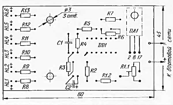
Pllaka e qarkut të printuar të voltmetrit LED në bord me një diagram të rregullimit të pjesëve në të, me përmasa 80x45 mm, tregohet në figurat më poshtë:

Kur vendosni një voltmetër LED në bord, në vend të një baterie, lidhni një burim të stabilizuar laboratorik 10 volt, duke instaluar një rezistencë të përkohshme prerëse në vend të rezistencës R1. Duke ndryshuar rezistencën R1, arrijmë momentin kur LED HL1 ndizet. Nivelet e mbetura vendosen automatikisht. Kur kontrolloni në detaje nivelet e mbetura, specifikohen respektivisht rezistencat R2 – R6.