Për të vizualizuar nivelin e sinjalit, përdoren gjerësisht treguesit LED të bazuar në arkitekturën e mikroqarqeve të specializuara. Ato përdoren në një gamë të gjerë pajisjesh: tregues të nivelit të sinjalit hyrës të pajisjeve marrëse të radios, tregues të nivelit në një përforcues audio, testues për korrigjimin e qarqeve që përdorin parimin e frekuencës së pulsit të kontrollit të ngarkesës.
Të gjithë treguesit e nivelit bazohen në krahasues me shumë faza.
Krahasuesi - një element logjik që krahason parametrat e dy sinjaleve hyrëse.
Sinjali që analizohet furnizohet në një kanal të krahasuesit, dhe tensioni i krahasimit të referencës furnizohet në të dytin. Nëse amplituda e së parës është më e lartë se tensioni i referencës, në dalje shfaqet një logjik, nëse më i ulët, shfaqet një zero logjike.
Funksionimi i krahasuesit më të thjeshtë mund të demonstrohet në mikroqarkun K155LN1, grupi i njësive i të cilit është elementi "NUK".

Një mikroqark i tillë është krahasuesi më i thjeshtë logjik. Kur tensioni i hyrjes është nga 0V në 2.4V (që korrespondon me zero logjike) dalja është 2.7V, sapo tensioni i hyrjes kalon 2.4V, sinjali i daljes do të bjerë në zero volt.
Ka disa çipa për vizualizimin e nivelit. Qarqet më shumëfunksionale, për mendimin tim, ju lejojnë të krijoni mikroqarqe bazuar në arkitekturën lm39xx. Kjo linjë përfshin tre mikroqarqe: lm3914, lm3915 dhe lm3916. Shkëputja minimale ju lejon të krijoni lehtësisht një tregues të nivelit të zërit LED me duart tuaja, edhe pa njohuri të thella të elektronikës radio.
Të gjithë ata përfaqësojnë një analizues me dhjetë breza. Ato ndryshojnë në mënyrën se si e diferencojnë sinjalin e hyrjes. Për lm3914 është 1V, për lm3915 është 3dB, për lm3916 është 1db.
Treguesi i nivelit të audios LED në lm3915
Le të mbledhim një tregues vëllimi në LED duke përdorur krahasues në lm3915.

Le të kuptojmë se si funksionon skema.
Sinjali që analizohet merret në hyrjen 5; amplituda e tij duhet të jetë 10 V. Për të përputhur amplitudën e sinjalit në hyrje, na duhet një ndërprerës tranzistor. Sinjali i analizuar furnizohet në bazën e tij përmes një ndarësi të tensionit të rezistencës në R5.
 Struktura logjike e lm3915
 Treguesi i zërit në lm3915 mund të funksionojë në dy mënyra treguese - "pika" dhe "kolona". Në rastin e parë, LED që korrespondon me nivelin aktual të sinjalit ndizet, në të dytën - të gjitha LED nga zero në nivelin aktual. Ndërrimi i mënyrave të treguesit kryhet përmes një ndërprerës midis telit të përbashkët dhe hyrjes "9".
Aplikim jo standard
 Një tregues që përdor lm3914 mund të përdoret si një testues kompakt për bateritë dhe akumulatorët e vegjël.
Tensioni i furnizimit të një qarku të tillë është nga 5 V në 12 V. Mundësohet lehtësisht nga Krona ose katër bateri AAA.
Kondensatori C1 - 50 µF 25V, rezistenca tërheqëse R1 - 1Mohm. R2, R3 - 4,7-5 kOhm secila. Gama e matjes së qarkut është 1V me një shkallëzim prej 0.1V. R2 rregullon diapazonin e matjes, R3 – rryma LED. Nëse fikni daljen 9, treguesi do të jetë një "kolona", por elementët e furnizimit me energji shkarkohen shpejt.
Pershendetje te gjitheve. Unë montoja qarqe të tilla duke përdorur llamba dhe kur LED-të u bënë më të disponueshme, . Kur u shfaq Interneti, u derdh një bollëk i tillë qarqesh, por u shfaq një problem i madh - ju bashkoni qarkun, dhe ai ose nuk funksionon fare ose funksionon, por jo siç duhet, dhe më pas filloni të bëni eksperimente me të, për të arritur rezultatin e dëshiruar. Por, ndërsa ndërhyn me qarkun, mëson shumë gjëra interesante, kupton se çfarë detaji ndikon në çfarë dhe në përgjithësi zhvillohesh në maksimum. Këtu janë disa skema vërtet të testuara dhe 100% funksionale që mund t'i bëni me siguri.
Koleksioni i qarqeve të treguesve AF LED
Këtu janë disa skema të tjera të treguesve të nivelit të përshtatura për pulsimin e mirë nga muzika


Këtu është një strob tjetër i kontrolluar nga një sinjal zanor që kam bërë dikur, ndoshta do të jetë i dobishëm për dikë tjetër:

I bëra këto dy drita strobe, njëra si polic, tjetra si disko.


Ky tregues ishte ende i bashkuar.

Dhe ky tregues u përforcua nën një ngarkesë të fuqishme.

Sa i përket këtij treguesi, LED-et duhet të jenë të gjitha me të njëjtën ngjyrë; kjo është një parakusht, pasi vetë shkalla është pasive.

Tani këtu është një qark interesant, disi mora një LED me dy ngjyra, kështu që vendosa ta bëj atë të pulsojë bukur në muzikë - ky është qarku që doli.


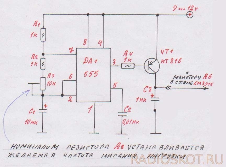
Por edhe një qark i tillë i specializuar tregues si 3915 kërkon qarkun e vet të kontrollit, më i përshtatshmi është ai në qark, pjesët zgjidhen gjithashtu për performancën më të mirë. Meqenëse ka një hyrje shumë të ndjeshme, në hyrjen e sinjalit shtohet një ndarës. Një rezistencë R7 u shtua për të parandaluar ndezjen e LED-së së parë. Por qarku shndërrohet në mënyrë të përkryer në një filtër të thjeshtë të frekuencës aktive. Le ta marrim këtë figurë si shembull, gjithçka varet nga kapaciteti i kondensatorit të hyrjes C1 dhe kondensatorit shtesë C5, i cili vendoset midis kolektorit dhe telit të përbashkët.

Në këtë mënyrë, ju mund të krijoni tre kanale frekuencash dhe tashmë të aplikoni të gjithë këtë gjë në DMU. Për të filluar, mund të lidhni një përforcues të tillë para-drive me rregullatorë për secilin kanal dhe të ngarkoni një LM me qarqet kontrolli të konfiguruara në dalje të rregullatorëve (rezistenca të ndryshueshme).gama e frekuencës së saj.

Gjithashtu, nëse dikush ka nevojë që treguesi të funksionojë thjesht në bateri, ose me fjalë të tjera, një instrument që vendos ritmin e një melodie, ky version i qarkut të kontrollit është shumë i përshtatshëm për këto qëllime.

Dhe së fundi, në instalimet elektrike të mikrocirkut ekziston një rezistencë e tillë R6, përmes tij plusi i zakonshëm furnizohet me LED, mund të shkëputet nga plusi kryesor dhe të lidhet me këtë qark ndërprerës, atëherë LED-të në kolonë nuk do të vetëm shkëlqim por edhe dridhje, efekti është i lezetshëm, e bëra edhe këtë.
Diskutoni artikullin TREGUESIT E NIVELIVE TË TINGUT NË LED
Treguesi i zërit DIY në LED. Një qark i thjeshtë me dy transistorë që kontrollon dridhjen e treguesve LED për tinguj të ndryshëm.
Dridhja do të përkojë me ritmin ose shkallën e ndryshimit të zërit. Saldimi është mjaft i thjeshtë dhe çdo person kureshtar i armatosur me një hekur saldimi mund të përballojë montimin e qarkut. Autori ndan përvojën e tij në foto dhe demonstron funksionimin e qarkut të montuar në video. Të gjitha pjesët, së bashku me tabelën e qarkut të printuar, blihen në dyqanin online me një çmim qesharak.
Si të montoni një tregues të zërit me duart tuaja
Një qark i thjeshtë me funksionalitet të bukur që ju lejon të ndjeni kombinimin e zërit dhe dritës ose të bëheni pjesë e një sistemi automatizimi, paralajmërimi ose sigurie, megjithëse përdorime të tjera të qarkut janë të mundshme. Tensioni i funksionimit të treguesit të zërit është 3-4,5 volt.
Parimi i funksionimit të qarkut të treguesit të zërit
Qarku i treguesit të zërit përfshin një përforcues të zërit të mikrofonit dhe një kaskadë kontrolli të ndriçimit LED.
- Fuqia furnizohet në qark përmes bllokut të pinit JP. Kondensatori zbut luhatjet e tensionit. Fuqia furnizohet në qarkun e integruar të amplifikimit të mikrofonit përmes rezistencës R1.
- Sinjali i përforcuar nga mikrofoni dërgohet përmes një kondensatori 10uF në bazën e transistorit Q1. Sinjali i kolektorit të transistorit Q1 drejton transistorin Q2.
- Transistori Q2 kontrollon ndriçimin e LED-ve D1-D5.
- Nëse kërkohet një tension më i lartë i furnizimit për qarkun, atëherë është e nevojshme të instaloni një rezistencë shtesë në qarkun e energjisë me një vlerë nominale R4 10...100 Ohms.
Montimi i qarkut
Së pari ju duhet të shpaketoni paketimin me pjesët dhe të kontrolloni praninë dhe shënimin e pjesëve. Ju mund të zbuloni rezistencën e rezistorëve ose duke matur rezistencën me një testues, ose duke e deshifruar atë në shenjat e rezistorëve. Vlerësimet dhe sasitë e pjesëve janë paraqitur në tabelë.
| NR. | Emri i komponentit | Shenjat PCB | parametri | KOL |
| 1 | Rezistencë | R1 | 4,7 mijë | 1 |
| 2 | Rezistencë | R2 | 1 milion | 1 |
| 3 | Rezistencë | R3 | 10 mijë | 1 |
| 4 | C1 | 47uF | 1 | |
| 5 | Kondensator elektrolitik | C2 | 1uF | 1 |
| 6 | Transistor S9012 | Q1, Q2 | TO-92 | 2 |
| 7 | Mikrofoni | mikrofon | 1 | |
| 8 | Diodë që lëshon dritë | D1-D7 | 3 mm | 5-7 |
| 9 | Bllok pin | 2.54 mm 2P | 1 | |
| 10 | bordi i qarkut të printuar | 29*30 mm | 1 |
- Montimi mund të fillojë në çdo mënyrë. Autori filloi montimin duke instaluar LED. LED ka elektroda polare. Këshilla për instalimin tregohet në foto. Është e përshtatshme të instaloni së pari tre LED. Ngjitni telat në dërrasë dhe pritni telat e dalë me prerëse anësore.
- Tjetra, dy LED-të e mbetura janë bashkuar. Transistorët janë instaluar sipas çelësit të vizatuar në tabelë. Kondensatorët elektrolitikë gjithashtu kanë terminale të polarizuar. Elektroda negative është e shënuar në trup; nëse diçka nuk është e qartë, shihni.
- Ne kontrollojmë instalimin e saktë të pjesëve dhe saldimin. Ne furnizojmë energji, për shembull, nga tre bateri AA. Shikoni një video të funksionimit të qarkut të treguesit të zërit.
Megjithë thjeshtësinë e tij, një sërë pajisjesh mund të montohen në bazë të qarkut, për shembull:
- Pajisja sinjalizuese "QUIET" (ne instalojmë një qark për të ndriçuar banderolën "më të qetë");
- hartoni një tregues për nevojën për të pastruar kompjuterin nga pluhuri bazuar në rritjen e zhurmës nga procesori ose tifozi i kartës video;
- tregues i dritës për trokitje në derë ose manipulim të bravës, thjesht mbështeteni mikrofonin në bravën ose fletën e derës;
- bëni një çelës automatik të fenerëve në një lodër të kontrolluar me radio; kur motori bën zhurmë, fenerët do të ndizen.
Një grup pjesësh për montimin e një treguesi të zërit LED mund të blihen nga lidhja e mëposhtme http://s.click.aliexpress.com/e/eqNvB6y . Nëse dëshironi të praktikoni seriozisht bashkimin e strukturave të thjeshta, Master rekomandon blerjen e një grupi prej 9 grupesh, të cilat do të kursejnë shumë kostot tuaja të transportit. Këtu është lidhja për të blerë http://ali.pub/2bkb42 . Mjeshtri mblodhi të gjitha kompletet dhe ata filluan të punojnë.
Fat i mirë dhe rritje e aftësive tuaja të saldimit.
UMZCH-të duken bukur dhe me stil, vetëm ku mund t'i gjeni... Ka një rrugëdalje - do të bëjmë një matës në të cilin rolin e shigjetës do ta luajnë diodat që lëshojnë dritë të kontrolluara nga një mikroqark. LM3916- Ky është një çip i veçantë për treguesit e nivelit LED.
Diagrami i një treguesi LED

LED-et lidhen përmes lidhësve J3 - J12 (vetëm një rresht LED tregohet në diagram). Qarku i treguesit do të kërkojë një furnizim me energji bipolare për të funksionuar siç duhet. Potenciali pozitiv i furnizimit të shiritave LED duhet të jetë nën +25 V dhe, në kombinim me tensionin negativ, nuk duhet të kalojë 36 V. Niveli minimal i tensionit varet nga voltazhi i funksionimit të LED-ve. Për shembull, nëse LED është 1.9V, dhe ne kemi 7 LED për pin, atëherë voltazhi minimal pozitiv do të jetë 7 x 1.9V + 1.5V (rënia e tensionit në LM3916) = 14.8 volt. LED-et jeshile priren të kenë një tension pak më të lartë prej 2.2-2.4V, kështu që +18V do të jetë e mjaftueshme në shumicën e rasteve.

Rryma LED përcaktohet nga rezistenca R1_REF, dhe me një rezistencë prej 2.2 kOhm do të ketë 5 mA.
Formula për llogaritjen: Iled = 10 x (1,2 V / R1_REF)

Ju mund të përdorni TL072, TL082, LM358 si një përforcues operacional të dyfishtë në hyrje. Modaliteti i daljes mund të vendoset nga kërcyesi me 3 kunja JP1. Tensioni maksimal i hyrjes për LM3916 është 1.2V dhe R8-R7 mund të përdoret për të rregulluar nivelin e hyrjes.
Video e treguesit
Ngjyra LED e zgjedhjes suaj. Përdoret këtu jeshile LED për nivele negative, e verdhe- 0dB dhe e kuqe për nivelin pozitiv të sinjalit audio. Për këtë ju nevojiten LED drejtkëndëshe. Ekziston një arkiv me vizatime të bordeve të qarkut të printuar.
Përcaktimi i nivelit të sinjalit në LED tregues është i nevojshëm për të zgjidhur disa probleme (treguesit e rrymës dhe tensionit, ndryshimet e fazës), por më shpesh një qark i tillë përdoret posaçërisht për të shfaqur nivelin e zërit.
Në elektronikën moderne, LED-të e treguesve u kanë lënë pjesërisht vendin pajisjeve të bazuara në LCD dhe matrica LED. Por një qark i këtij lloji jo vetëm që tregon qartë nivelin e sinjalit, por është gjithashtu i lehtë për t'u zbatuar dhe mjaft vizual.
Nga çfarë të montoni një tregues të nivelit LED?
Konvertuesit analog në dixhital (ADC) LM3914-16 mund të merren si bazë. Këto çipa janë të afta të drejtojnë të paktën 10 dioda, dhe me shtimin e çipave të rinj, numri i llambave mund të rritet pothuajse pafundësisht. Treguesi mund të ketë çdo ngjyrë, dhe është më mirë të mendoni paraprakisht për modelin e rastit, në mënyrë që të mos bëhet surprizë më vonë.
LM3914 ka një shkallë lineare, e cila mund të përdoret gjithashtu për të matur tensionin, dhe 15 dhe 16 kanë një shkallë logaritmike, por pika e mikroqarqeve nuk është e ndryshme.
Në këtë rast, LED mund të jenë të çdo lloji, të importuar ose vendas, gjëja kryesore është se ato janë të përshtatshme për detyrën në fjalë. Për shembull, mund të përdorni diodat më të thjeshta AL307, por mund të përdorni edhe ato më komplekse.
Llogaritja e skemës së treguesve
Kompozimi i kësaj pajisjeje nuk kërkon ndonjë aftësi të veçantë. Llogaritja e treguesve të rrymës dhe tensionit mund të bëhet në çdo program, si një vizatim.
Njëra nga "këmbët" (9) të mikroqarkut është e lidhur me hyrjen e tensionit pozitiv. Në këtë mënyrë LED-të do të kontrollohen si një kolonë e vetme. Për të qenë në gjendje të rregulloni në mënyrë të pavarur mënyrat kur ndryshoni fazat, qarku duhet të përfshijë një ndërprerës, por mund të bëjë lehtësisht pa të nëse ky opsion nuk është i nevojshëm.
Rryma që kalon nëpër LED për një tension dhe fazë të caktuar mund të llogaritet si më poshtë:
R - rezistenca në këmbët 7 dhe 8
Për një rrymë prej 1 mA R=12,5 / 0,001 A = 12,5 kOhm.
Dhe për një rrymë prej 20mA R=625 Ohm.
Futja e një rezistence prerëse do të bëjë të mundur rregullimin e shkëlqimit të shkëlqimit; nëse nuk ka nevojë të tillë, mund të instaloni një të rregullt. Vlerësimet për ta do të jenë përkatësisht 10 kOhm dhe 1 kOhm.
Qarku përfundimtar i treguesit të nivelit LED do të duket diçka si kjo.
Është ideal për një sinjal mono, por për stereo do të duhet të krijoni një tjetër për kanalin e dytë. Ato mund të lidhen përmes një kabllo rrjeti të rregullt, duke marrë parasysh fazën. Një opsion i shkëlqyer është të bëni dy diagrame identike, të bëra me ngjyra të ndryshme për të demonstruar nivelin e secilit kanal. Pajisjet gjithashtu mund të ndryshojnë gamën e tyre të ngjyrave, por ky zbatim do të jetë disi më i ndërlikuar.
Vlera e C3 mund të jetë e barabartë me 1 µF, me kusht që R4 = 100 kOhm. Vlerësimi R2 mund të zgjidhet nga diapazoni 47-100 kOhm.
Ky qark përdor një transistor KT 315, por ai mund të zëvendësohet me ndonjë tjetër me parametra të përshtatshëm (faza e sinjalit, rryma, faza e tensionit, kryqëzimi p-n).
Këshillë: Të gjithë elementët e nevojshëm mund të blihen në tregun e radios ose në një dyqan; ia vlen të merret parasysh që çipat LM3915-16 janë pak më të shtrenjtë se LM3914. Një opsion më pak i kushtueshëm është shkrirja e komponentëve nga bordet ekzistuese.
Rezultati përfundimtar do të jetë diçka si kjo:

Montimi i një treguesi të nivelit të sinjalit vetë është një detyrë plotësisht e zgjidhshme. Gjëja kryesore është të gjeni se nga do të përbëhet qarku, dhe më pas të kaloni pak kohë duke kontrolluar dhe korrigjuar pajisjen.