O sursă de alimentare de înaltă calitate cu tensiune de ieșire reglabilă este visul oricărui radioamator începător. În viața de zi cu zi, astfel de dispozitive sunt folosite peste tot. De exemplu, luați orice încărcător pentru un telefon sau laptop, sursă de alimentare pentru o jucărie pentru copii, consolă de jocuri, telefon fix și multe alte aparate electrocasnice.
În ceea ce privește implementarea circuitului, Designul surselor poate fi diferit:
- cu transformatoare de putere, o punte de diode cu drepturi depline;
- convertoare de impulsuri ale tensiunii de rețea cu tensiune de ieșire reglabilă.
Dar pentru ca sursa să fie fiabilă și durabilă, este mai bine să alegeți o bază de element de încredere pentru ea. Aici încep să apară dificultățile. De exemplu, alegând componente produse intern ca componente de reglare, stabilizare, pragul de tensiune inferior este limitat la 5 V. Dar dacă este necesar 1,5 V? În acest caz, este mai bine să utilizați analogi importați. Mai mult, sunt mai stabile și practic nu se încălzesc în timpul funcționării. Una dintre cele mai utilizate este stabilizator integral lm317t.
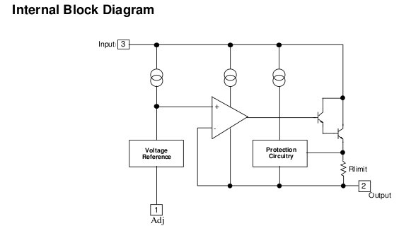
Caracteristici principale, topologia cipului
 Cipul lm317 este universal. Poate fi folosit ca stabilizator cu o tensiune de iesire constanta si ca stabilizator reglabil cu randament ridicat. MS are caracteristici practice ridicate care fac posibilă utilizarea în diferite circuite de încărcare sau surse de alimentare de laborator. În același timp, nici nu trebuie să vă faceți griji cu privire la funcționarea fiabilă sub sarcini critice, deoarece microcircuitul este echipat cu protecție internă la scurtcircuit.
Acesta este un plus foarte bun, deoarece curentul maxim de ieșire al stabilizatorului pe lm317 nu este mai mare de 1,5 A. Dar a avea protecție vă va împiedica să îl ardeți accidental. Pentru a crește curentul de stabilizare, este necesar să folosiți tranzistori suplimentari. Astfel, curenții de până la 10 A sau mai mult pot fi reglați la utilizarea componentelor adecvate. Dar despre asta vom vorbi mai târziu, iar în tabelul de mai jos vă vom prezenta principalele caracteristici ale componentei.
Pinout microcircuit
Un circuit integrat a fost fabricat într-un pachet standard TO-220 cu un radiator montat pe un radiator. În ceea ce privește numerotarea pinii, aceștia sunt localizați conform GOST de la stânga la dreapta și au următoarea semnificație:
Pinul 2 este conectat la un radiator fără izolator, deci în dispozitive dacă radiatorul este în contact cu carcasa, trebuie folosiți izolatori de mica sau orice alt material termoconductor. Acesta este un punct important, deoarece puteți scurtcircuita accidental pinii și pur și simplu nu va exista nimic la ieșirea microcircuitului.
Analogii lm317
 Uneori nu este posibil să găsiți microcircuitul necesar în mod special pe piață, atunci puteți utiliza altele similare. Printre componentele interne de pe lm317, există un analog destul de puternic și productiv. El este microcircuit KR142EN12A. Dar atunci când îl utilizați, merită să luați în considerare faptul că nu poate furniza o tensiune mai mică de 5 V la ieșire, așa că, dacă acest lucru este important, va trebui din nou să utilizați un tranzistor suplimentar sau să găsiți exact componenta necesară.
În ceea ce privește factorul de formă, KR are același număr de pini ca și lm317. Prin urmare, nici măcar nu trebuie să refaceți circuitul dispozitivului finit pentru a regla parametrii regulatorului de tensiune sau stabilizatorului neschimbabil. La instalarea unui circuit integrat Se recomanda instalarea lui pe un calorifer cu sistem bun de disipare a caldurii si racire. Acest lucru se observă destul de des la fabricarea lămpilor LED puternice. Dar la sarcina nominală dispozitivul generează puțină căldură.
Pe lângă circuitul integrat intern KR142EN12, se produc analogi importați mai puternici, ai căror curenți de ieșire sunt de 2-3 ori mai mari. Astfel de microcircuite includ:
- lm350at, lm350t - 3 A;
- lm350k - 3 A, 30 W în alt caz;
- lm338t, lm338k - 5 A.
Producătorii acestor componente garantează o stabilitate mai mare a tensiunii de ieșire, un curent de reglare scăzut, o putere crescută cu aceeași tensiune minimă de ieșire de cel mult 1,3 V.
Caracteristici de conectare
 Pe lm317t, circuitul de comutare este destul de simplu și constă dintr-un număr minim de componente. Cu toate acestea, numărul lor depinde de scopul dispozitivului. Dacă se fabrică un stabilizator de tensiune, va necesita următoarele părți:
Rs este o rezistență la șunt, care acționează și ca balast. Selectați o valoare de aproximativ 0,2 Ohm dacă doriți să furnizați un curent de ieșire maxim de până la 1,5 A.
Rezistivul se împarte cu R1, R2, conectat la ieșire și la carcasă, iar tensiunea de reglare vine din punctul de mijloc, formând un feedback profund. Datorită acestui fapt, se obține un coeficient de ondulare minim și o stabilitate ridicată a tensiunii de ieșire. Rezistența lor este selectată pe baza raportului 1:10: R1=240 Ohm, R2=2,4 kOhm. Acesta este un circuit regulator de tensiune tipic cu o tensiune de ieșire de 12 V.
Dacă trebuie să proiectați un stabilizator de curent, Acest lucru va necesita și mai puține componente:
R1, care este un șunt. Ei setează curentul de ieșire, care nu trebuie să depășească 1,5 A.
Pentru a calcula corect circuitul unui anumit dispozitiv, întotdeauna puteți folosi calculatorul lm317. În ceea ce privește calculul Rs, acesta poate fi determinat folosind formula uzuală: Iout. = Uop/R1. Pe lm317, stabilizatorul de curent LED este de o calitate destul de înaltă, care poate fi realizat de mai multe tipuri în funcție de puterea LED-ului:
- pentru a conecta un LED de un singur watt cu un consum de curent de 350mA, trebuie să utilizați Rs = 3,6 Ohm. Puterea sa este selectată să fie de cel puțin 0,5 W;
- Pentru a alimenta LED-uri de trei wați, veți avea nevoie de un rezistor cu o rezistență de 1,2 Ohm, curentul va fi de 1 A, iar puterea de disipare va fi de cel puțin 1,2 W.
Pe lm317, stabilizatorul de curent LED este destul de fiabil, dar este important să se calculeze corect rezistența de șunt și să se selecteze puterea acesteia. Un calculator vă va ajuta în această problemă. De asemenea, diverse lămpi puternice și spoturi de casă sunt realizate folosind LED-uri și pe baza acestui MS.
Construirea de surse de alimentare puternice reglementate
 Tranzistorul intern lm317 nu este suficient de puternic, pentru a-l crește va trebui să îl folosiți tranzistori suplimentari externi. În acest caz, componentele sunt selectate fără restricții, deoarece controlul lor necesită curenți mult mai mici, pe care microcircuitul este destul de capabil să îi ofere.
Sursa de alimentare reglată lm317 cu un tranzistor extern nu este mult diferită de cea obișnuită. În loc de o constantă R2, este instalat un rezistor variabil, iar baza tranzistorului este conectată la intrarea microcircuitului printr-un rezistor limitator suplimentar care oprește tranzistorul. Un comutator bipolar cu conductivitate p-n-p este utilizat ca unul controlat. În acest design, microcircuitul funcționează cu curenți de aproximativ 10 mA.
La proiectarea surselor de alimentare bipolare va trebui să utilizați perechea complementară a acestui cip, care este lm337. Și pentru a crește curentul de ieșire, se folosește un tranzistor cu conductivitate n-p-n. În brațul invers al stabilizatorului, componentele sunt conectate în același mod ca și în brațul superior. Circuitul primar este un transformator sau o unitate de impuls, care depinde de calitatea circuitului și de eficiența acestuia.
Unele caracteristici ale lucrului cu cipul lm317
Atunci când proiectați surse de alimentare cu o tensiune de ieșire scăzută, la care diferența dintre valorile de intrare și de ieșire nu depășește 7 V, este mai bine să utilizați alte microcircuite, mai sensibile, cu un curent de ieșire de până la 100 mA - LP2950 și LP2951. La cădere scăzută, lm317 nu este capabil să ofere coeficientul de stabilizare necesar, ceea ce poate duce la pulsații nedorite în timpul funcționării.
Alte circuite practice pe lm317
Pe lângă stabilizatorii convenționali și regulatoarele de tensiune bazate pe acest cip, există și Puteți face un regulator digital de tensiune?. Pentru a face acest lucru, veți avea nevoie de microcircuitul în sine, un set de tranzistori și mai multe rezistențe. Prin pornirea tranzistoarelor și la primirea unui cod digital de la un computer sau alt dispozitiv, rezistența R2 se modifică, ceea ce duce, de asemenea, la o modificare a curentului circuitului în intervalul de tensiune de la 1,25 la 1,3 V.
Dacă circuitul necesită un stabilizator pentru o tensiune non-standard, atunci o soluție excelentă este utilizarea popularului stabilizator integrat LM317T cu următoarele caracteristici:
- capabil să funcționeze în intervalul de tensiune de ieșire de la 1,2 la 37 V;
- curentul de ieșire poate ajunge la 1,5 A;
- putere maximă disipată 20 W;
- limitare de curent încorporată pentru protecția la scurtcircuit;
- protecție la supraîncălzire încorporată.
Pentru microcircuitul LM317T, circuitul de conectare minim presupune prezența a două rezistențe, ale căror valori de rezistență determină tensiunea de ieșire, un condensator de intrare și de ieșire.
Stabilizatorul are doi parametri importanți: tensiunea de referință (Vref) și curentul care curge din pinul de reglare (Iadj).
Valoarea tensiunii de referință poate varia de la o instanță la alta de la 1,2 la 1,3 V și, în medie, este de 1,25 V. Tensiunea de referință este tensiunea pe care cipul stabilizator se străduiește să o mențină peste rezistorul R1. Astfel, dacă rezistorul R2 este închis, atunci ieșirea circuitului va fi de 1,25 V și cu cât căderea de tensiune pe R2 este mai mare, cu atât tensiunea de ieșire va fi mai mare. Se pare că 1,25 V pe R1 se adună cu scăderea pe R2 și formează tensiunea de ieșire.
Dar aș sfătui să folosiți LM317T în cazul tensiunilor tipice, doar atunci când aveți nevoie urgent să faceți ceva în genunchi și un microcircuit mai potrivit precum 7805 sau 7812 nu este la îndemână.
Și iată locația pinout-ului LM317T:
- Reglare
- Zi libera
- Intrare
Apropo, analogul casnic al LM317 - KR142EN12A - are exact același circuit de conectare.

Este ușor să realizați o sursă de alimentare reglabilă pe acest microcircuit: înlocuiți constanta R2 cu una variabilă, adăugați un transformator de rețea și o punte de diode.

De asemenea, puteți face un circuit de pornire ușoară pe LM317: adăugați un condensator și un amplificator de curent pe un tranzistor bipolar pnp.

De asemenea, circuitul de conectare pentru controlul digital al tensiunii de ieșire nu este complicat. Calculăm R2 pentru tensiunea maximă necesară și adăugăm lanțurile unui rezistor și un tranzistor în paralel. Pornirea tranzistorului va adăuga, în paralel cu conductivitatea rezistorului principal, conductivitatea celui suplimentar. Și tensiunea de ieșire va scădea.

Circuitul stabilizatorului de curent este chiar mai simplu decât stabilizatorul de tensiune, deoarece este nevoie de un singur rezistor. Iout = Uop/R1.
De exemplu, în acest fel obținem un stabilizator de curent pentru LED-uri de la lm317t:
- pentru LED-uri de un singur watt I = 350 mA, R1 = 3,6 Ohm, putere de cel puțin 0,5 W.
- pentru LED-uri de trei wați I = 1 A, R1 = 1,2 Ohm, putere de cel puțin 1,2 W.

Este ușor să faci un încărcător pentru baterii de 12 V pe baza stabilizatorului, asta ne oferă fișa tehnică. Rs poate fi folosit pentru a seta limita de curent, în timp ce R1 și R2 determină limita de tensiune.

Dacă circuitul trebuie să stabilizeze tensiuni la curenți mai mari de 1,5 A, atunci LM317T poate fi folosit în continuare, dar împreună cu un tranzistor bipolar puternic al structurii pnp.
Dacă trebuie să construim un stabilizator de tensiune reglabil bipolar, atunci un analog al LM317T ne va ajuta, dar lucrând în brațul negativ al stabilizatorului - LM337T.

Dar acest cip are și limitări. Nu este un regulator cu pierderi reduse; dimpotrivă, începe să funcționeze bine numai atunci când diferența dintre tensiunea de ieșire și cea de ieșire depășește 7 V.
Dacă curentul nu depășește 100mA, atunci este mai bine să utilizați circuite integrate cu pierdere redusă LP2950 și LP2951.
Analogi puternici ai LM317T - LM350 și LM338
Dacă curentul de ieșire de 1,5 A nu este suficient, atunci puteți utiliza:
- LM350AT, LM350T - 3 A și 25 W (pachet TO-220)
- LM350K - 3 A și 30 W (pachet TO-3)
- LM338T, LM338K - 5 A
Producătorii acestor stabilizatori, pe lângă creșterea curentului de ieșire, promit un curent de intrare de control redus la 50 μA și o precizie îmbunătățită a tensiunii de referință.
Dar circuitele de comutare sunt potrivite pentru LM317.
Cărțile de referință ale componentelor (sau fișele tehnice) sunt esențiale
la dezvoltarea circuitelor electronice. Cu toate acestea, au o caracteristică neplăcută.
Faptul este că documentația pentru orice componentă electronică (de exemplu, un microcircuit)
ar trebui să fie întotdeauna gata chiar înainte ca acest cip să înceapă să fie produs.
Ca urmare, în realitate avem o situație în care microcircuitele sunt deja la vânzare,
și nici un singur produs bazat pe ele nu a fost încă creat.
Aceasta înseamnă că toate recomandările și în special diagramele de aplicare date în fișele tehnice,
sunt de natură teoretică și consultativă.
Aceste circuite demonstrează în principal principiile de funcționare ale componentelor electronice,
dar nu au fost testate în practică și, prin urmare, nu ar trebui luate în considerare orbește
în timpul dezvoltării.
Aceasta este o stare de lucruri normală și logică, chiar dacă numai în timp și ca
Pe măsură ce experiența se acumulează, se fac modificări și completări în documentație.
Practica arată contrariul - în majoritatea cazurilor, toate soluțiile de circuit
prezentate în fișa tehnică rămân la nivel teoretic.
Și, din păcate, adesea acestea nu sunt doar teorii, ci greșeli grave.
Și și mai regretabilă este discrepanța dintre real (și cel mai important)
parametrii microcircuitului menționați în documentație.
Ca exemplu tipic de astfel de fișe de date, iată o carte de referință pentru LM317, -
stabilizator de tensiune reglabil cu trei terminale, care, apropo, este produs
de aproximativ 20 de ani.Dar diagramele și datele din fișa lui de date sunt încă aceleași...
Deci, dezavantajele LM317 ca microcircuit și erori în recomandările de utilizare.
1. Diode de protectie.
Diodele D1 și D2 servesc la protejarea regulatorului, -
D1 este pentru protecția la scurtcircuit la intrare și D2 este pentru protecția la descărcare
condensatorul C2 „prin rezistența scăzută de ieșire a regulatorului” (cit).
De fapt, dioda D1 nu este necesară, deoarece nu există niciodată o situație în care
tensiunea la intrarea regulatorului este mai mică decât tensiunea de ieșire.
Prin urmare, dioda D1 nu se deschide niciodată și, prin urmare, nu protejează regulatorul.
Cu excepția, desigur, în cazul unui scurtcircuit la intrare. Dar aceasta este o situație nerealistă.
Dioda D2 se poate deschide, desigur, dar condensatorul C2 se descarcă perfect
iar fără el, prin rezistențele R2 și R1 și prin rezistența de sarcină.
Și nu este nevoie să-l descarci în mod special.
În plus, mențiunea în fișa tehnică a „descărcării C2 prin ieșirea regulatorului”
nimic mai mult decât o eroare, deoarece circuitul etajului de ieșire al regulatorului este
Acesta este un adept emițător.
Iar condensatorul C2 pur și simplu nu poate fi descărcat prin ieșirea regulatorului.
2. Acum - despre cel mai neplăcut lucru, și anume discrepanța dintre real
caracteristicile electrice declarate.
Fișele tehnice ale tuturor producătorilor au parametrul Adjustment Pin Current
(curent la intrarea de reglare). Parametrul este foarte interesant și important, determinant
în special, valoarea maximă a rezistenței în circuitul de intrare Adj.
Și, de asemenea, valoarea condensatorului C2. Valoarea curentă tipică declarată Adj este 50 µA.
Ceea ce este foarte impresionant și mi s-ar potrivi complet ca designer de circuite.
Daca de fapt nu ar fi de 10 ori mai mare, i.e. 500 µA.
Aceasta este o discrepanță reală, testată pe microcircuite de la diferiți producători
și de mulți ani.
Totul a început cu nedumerire - de ce există un divizor atât de cu rezistență scăzută la ieșire în toate circuitele?
Dar de aceea are rezistență scăzută, pentru că altfel este imposibil să obțineți LM317 la ieșire
nivelul minim de tensiune.
Cel mai interesant lucru este că în tehnica actuală de măsurare Adj divizor de rezistență scăzută
este prezent și la ieșire. Ceea ce înseamnă de fapt este că acest separator este pornit
paralel cu electrodul Adj.
Numai cu o astfel de abordare vicleană vă puteți „încadra” în valoarea tipică de 50 μA.
Dar acesta este un truc destul de elegant. „Condiții speciale de măsurare”.
Înțeleg că este foarte dificil să se realizeze un curent stabil de valoarea declarată de 50 μA.
Deci, nu scrie o minciună în fișa de date. În rest, este o înșelăciune a cumpărătorului. Iar onestitatea este cea mai bună politică.
3. Mai multe despre cel mai neplăcut lucru.
Fișele tehnice LM317 are un parametru de reglare linie care determină
intervalul de tensiune de funcționare. Și intervalul indicat nu este rău - de la 3 la 40 de volți.
Există doar un mic DAR...
Partea internă a LM317 conține un stabilizator de curent care utilizează
Dioda Zener pentru tensiune 6,3 V.
Prin urmare, reglarea eficientă începe cu o tensiune de intrare-ieșire de 7 volți.
În plus, treapta de ieșire a LM317 este un tranzistor n-p-n conectat conform circuitului
adept emițător. Și pe „boost” are aceleași repetoare.
Prin urmare, funcționarea eficientă a LM317 la o tensiune de 3 V este imposibilă.
4. Despre circuite care promit să obțină o tensiune reglabilă de la zero volți la ieșirea lui LM317.
Tensiunea minimă de ieșire a LM317 este de 1,25 V.
Ar fi fost posibil să obțineți mai puțin dacă nu ar fi circuitul de protecție încorporat împotriva
scurtcircuit la ieșire. Nu este cea mai bună schemă, ca să spunem ușor...
În alte microcircuite, circuitul de protecție la scurtcircuit este declanșat atunci când curentul de sarcină este depășit.
Și în LM317 - când tensiunea de ieșire scade sub 1,25 V. Simplu și cu gust -
Tranzistorul se oprește atunci când tensiunea bază-emițător este sub 1,25 V și asta este tot.
De aceea, toate schemele de aplicații care sunt promise a fi scoase
LM317 tensiune reglabilă, începând de la zero volți - nu funcționează.
Toate aceste circuite sugerează conectarea pinului Adj printr-un rezistor la sursă
tensiune negativă.
Dar deja când tensiunea dintre ieșire și contactul Adj este mai mică de 1,25 V
circuitul de protecție la scurtcircuit va funcționa.
Toate aceste scheme sunt pură fantezie teoretică. Autorii lor nu știu cum funcționează LM317.
5. Metoda de protecție la scurtcircuit de ieșire folosită în LM317 impune și
restricții cunoscute privind pornirea regulatorului - în unele cazuri pornirea va fi dificilă,
deoarece este imposibil să se facă distincția între modul scurtcircuit și modul normal de comutare,
când condensatorul de ieșire nu este încă încărcat.
6. Recomandările pentru valorile condensatorului la ieșirea lui LM317 sunt foarte impresionante -
acest interval este de la 10 la 1000 µF. Ce în combinație cu valoarea rezistenței de ieșire
un regulator de ordinul unei miimi de ohm este o prostie completă.
Chiar și studenții știu că condensatorul de la intrarea stabilizatorului este esențial
pentru a spune ușor, mai eficient decât rezultatul.
7. Despre principiul reglării tensiunii de ieșire LM317.
LM317 este un amplificator operațional în care reglarea
Tensiunea de ieșire este realizată prin intermediul intrării NOT inversoare Adj.
Cu alte cuvinte - de-a lungul circuitului de feedback pozitiv (POC).
De ce este rău? Și faptul că toate interferențele de la ieșirea regulatorului prin intrarea Adj trec în interiorul LM317,
și apoi - din nou la sarcină. Este bine că coeficientul de transmisie de-a lungul circuitului PIC este mai mic de unu...
Altfel am primi un autogenerator.
Și nu este surprinzător în acest sens că se recomandă instalarea condensatorului C2 în circuitul Adj.
Cel puțin, filtrează cumva interferențele și crește rezistența la autoexcitare.
De asemenea, este foarte interesant că în circuitul PIC, în interiorul LM317,
Există un condensator de 30 pF. Care crește nivelul de ondulație pe sarcină cu o frecvență crescândă.
Adevărat, acest lucru este arătat în mod sincer în diagrama Ripple Rejection. Dar pentru ce este acest condensator?
Ar fi foarte util dacă reglarea ar fi efectuată de-a lungul circuitului
Feedback negativ. Și în ceea ce privește valoarea PIC, nu face decât să înrăutățească stabilitatea.
Apropo, cu conceptul de Ripple Rejection în sine, nu totul este „în termeni de concepte”.
În înțelegerea general acceptată, această valoare înseamnă cât de bine este regulatorul
filtrează ondulațiile de la INPUT.
Și pentru LM317 înseamnă de fapt gradul de deteriorare proprie
și arată cât de bine LM317 luptă împotriva ondulațiilor, care în sine
îl ia de la ieșire și îl conduce din nou în interiorul său.
La alte regulatoare, reglarea se realizează printr-un circuit
Feedback negativ, care maximizează toți parametrii.
8. Despre curentul minim de sarcină pentru LM317.
Fișa de date specifică un curent de sarcină minim de 3,5 mA.
La un curent mai mic, LM317 este inoperant.
O caracteristică foarte ciudată pentru un stabilizator de tensiune.
Deci, trebuie să monitorizați nu numai curentul maxim de sarcină, ci și cel minim?
Aceasta înseamnă, de asemenea, că, cu un curent de sarcină de 3,5 mA, eficiența regulatorului nu depășește 50%.
Vă mulțumesc foarte mult, domnilor, dezvoltatori...
1. Recomandările de utilizare a diodelor de protecție pentru LM317 sunt de natură teoretică generală și au în vedere situații care nu apar în practică.
Și, deoarece se propune utilizarea unor diode Schottky puternice ca diode de protecție, obținem o situație în care costul protecției (inutile) depășește prețul LM317 în sine.
2. Fișa de date LM317 conține un parametru incorect pentru curentul la intrarea Adj.
Se măsoară în condiții „speciale” atunci când se conectează un divizor de ieșire cu impedanță scăzută.
Această tehnică de măsurare nu corespunde conceptului general acceptat de „curent de intrare” și arată incapacitatea de a atinge parametrii specificați în timpul fabricării LM317.
De asemenea, înșală cumpărătorul.
3. Parametrul Line Regulation este specificat ca un interval de la 3 la 40 Volti.
În unele circuite de aplicație, LM317 „funcționează” cu o tensiune de intrare-ieșire de până la doi volți.
De fapt, domeniul de reglare efectivă este de 7 - 40 de volți.
4. Toate circuitele pentru obținerea tensiunii reglate la ieșirea lui LM317, începând de la zero volți, sunt practic inoperabile.
5. Metoda de protecție la scurtcircuit LM317 este uneori folosită în practică.
Este simplu, dar nu cel mai bun. În unele cazuri, pornirea regulatorului nu va fi deloc posibilă.
7. LM317 implementează un principiu defect de reglare a tensiunii de ieșire -
de-a lungul circuitului de feedback pozitiv. Ar trebui să fie mai rău, dar nu poate fi mai rău.
8. Limitarea curentului minim de sarcină indică un design slab al circuitului LM317 și limitează în mod clar utilizarea acestuia.
Rezumând toate deficiențele LM317, putem da recomandări:
a) Pentru a stabiliza tensiuni „tipice” constante de 5, 6, 9, 12, 15, 18, 24 V, este recomandabil să folosiți stabilizatori cu trei terminale din seria 78xx și nu LM317.
b) Pentru a construi stabilizatori de tensiune cu adevărat eficienți, ar trebui să utilizați microcircuite precum LP2950, LP2951, capabile să funcționeze la o tensiune de intrare-ieșire mai mică de 400 de milivolți.
Combinat cu tranzistori de mare putere, dacă este necesar.
Aceste microcircuite funcționează eficient și ca stabilizatori de curent.
c) În cele mai multe cazuri, un amplificator operațional, o diodă zener și un tranzistor puternic (în special un tranzistor cu efect de câmp) vor oferi parametri mult mai buni decât LM317.
Și cu siguranță - cea mai bună reglare, precum și cea mai largă gamă de tipuri și valori de rezistențe și condensatoare.
G). Și, nu aveți încredere orbește în Datasheets.
Orice microcircuite sunt făcute și, ceea ce este tipic, vândute de oameni...
Destul de des este nevoie de un stabilizator de tensiune simplu. Acest articol oferă o descriere și exemple de utilizare a unui stabilizator de tensiune integrat ieftin (prețuri pentru LM317). LM317.
Lista sarcinilor rezolvate de acest stabilizator este destul de extinsă - aceasta include alimentarea diferitelor circuite electronice, dispozitive radio, ventilatoare, motoare și alte dispozitive de la rețea sau alte surse de tensiune, cum ar fi o baterie de mașină. Cele mai comune circuite sunt reglate de tensiune.
În practică, cu participarea lui LM317, puteți construi un stabilizator de tensiune pentru o tensiune de ieșire arbitrară în intervalul 3...38 volți.
Specificații:
- Tensiune de ieșire stabilizator: 1,2... 37 volți.
- Curent de încărcare de până la 1,5 amperi.
- Precizie de stabilizare 0,1%.
- Există protecție internă împotriva scurtcircuitului accidental.
- Protecție excelentă a stabilizatorului integrat împotriva unei posibile supraîncălziri.

Disiparea puterii și tensiunea de intrare a stabilizatorului LM317
Tensiunea la intrarea stabilizatorului nu trebuie să depășească 40 de volți și mai există o condiție - tensiunea de intrare minimă ar trebui să depășească tensiunea de ieșire dorită cu 2 volți.
Microcircuitul LM317 din pachetul TO-220 este capabil să funcționeze stabil la un curent de sarcină maxim de până la 1,5 amperi. Dacă nu utilizați un radiator de înaltă calitate, această valoare va fi mai mică. Puterea eliberată de microcircuit în timpul funcționării acestuia poate fi determinată aproximativ prin înmulțirea curentului de ieșire și a diferenței dintre potențialul de intrare și de ieșire.

Puterea de disipare maximă admisă fără radiator este de aproximativ 1,5 W la o temperatură ambientală de 30 de grade Celsius sau mai puțin. Dacă se asigură o bună disipare a căldurii din carcasa LM317 (nu mai mult de 60 g), puterea de disipare poate fi de 20 wați.
Când plasați un microcircuit pe un radiator, este necesar să izolați corpul microcircuitului de radiator, de exemplu, cu o garnitură de mică. De asemenea, este recomandabil să folosiți pastă termoconductoare pentru îndepărtarea eficientă a căldurii.
Selectarea rezistenței pentru stabilizatorul LM317
Pentru o funcționare precisă a microcircuitului, valoarea totală a rezistențelor R1...R3 trebuie să creeze un curent de aproximativ 8 mA la tensiunea de ieșire necesară (Vo), adică:
R1 + R2 + R3 = Vo / 0,008
Această valoare ar trebui considerată ideală. În procesul de selectare a rezistențelor, este permisă o ușoară abatere (8...10 mA).
Valoarea rezistenței variabile R2 este direct legată de domeniul tensiunii de ieșire. De obicei, rezistența sa ar trebui să fie de aproximativ 10...15% din rezistența totală a rezistențelor rămase (R1 și R2), sau puteți selecta rezistența sa experimental.
Amplasarea rezistențelor pe placă poate fi arbitrară, dar pentru o mai bună stabilitate este indicat să o plasați departe de radiatorul cipul LM317.
Stabilizarea și protecția circuitului
Capacitatea C2 și dioda D1 sunt opționale. Dioda protejează stabilizatorul LM317 de posibila tensiune inversă care apare în designul diferitelor dispozitive electronice.
Capacitatea C2 nu numai că reduce ușor răspunsul microcircuitului LM317 la schimbările de tensiune, dar reduce și influența interferențelor electrice atunci când placa stabilizatoare este plasată în apropierea locurilor cu radiații electromagnetice puternice.
unitate de putere - Acesta este un atribut indispensabil în atelierul de radioamatori. De asemenea, am decis să-mi construiesc o sursă de alimentare reglabilă, pentru că m-am săturat să cumpăr de fiecare dată baterii sau să folosesc adaptoare aleatorii. Iată o scurtă descriere: Sursa de alimentare reglează tensiunea de ieșire de la 1,2 Volți la 28 Volți. Și oferă o sarcină de până la 3 A (în funcție de transformator), care este cel mai adesea suficientă pentru a testa funcționalitatea modelelor de radio amatori. Circuitul este simplu, tocmai potrivit pentru un radioamator începător. Asamblat pe baza de componente ieftine - LM317Și KT819G.Circuit de alimentare reglat LM317
Lista elementelor circuitului:
- Stabilizator LM317
- T1 - tranzistor KT819G
- Tr1 - transformator de putere
- F1 - siguranta 0,5A 250V
- Br1 - punte de diode
- D1 - dioda 1N5400
- LED1 - LED de orice culoare
- C1 - condensator electrolitic 3300 uF*43V
- C2 - condensator ceramic 0,1 uF
- C3 - condensator electrolitic 1 µF * 43V
- R1 - rezistenta 18K
- R2 - rezistenta 220 Ohm
- R3 - rezistenta 0,1 Ohm*2W
- P1 - rezistenta constructiei 4.7K
Pinout a microcircuitului și a tranzistorului

Carcasa a fost luată de la sursa de alimentare a computerului. Panoul frontal este din PCB, este indicat sa instalati un voltmetru pe acest panou. Nu l-am instalat pentru că încă nu am găsit unul potrivit. Am instalat și cleme pentru firele de ieșire pe panoul frontal.


Am lăsat priza de intrare pentru a alimenta sursa de alimentare în sine. O placă de circuit imprimat realizată pentru montarea pe suprafață a unui tranzistor și a unui cip stabilizator. Au fost fixate la un radiator comun printr-o garnitură de cauciuc. Radiatorul era solid (se vede in poza). Trebuie luată cât mai mare posibil - pentru o răcire bună. Totuși, 3 amperi este mult!
